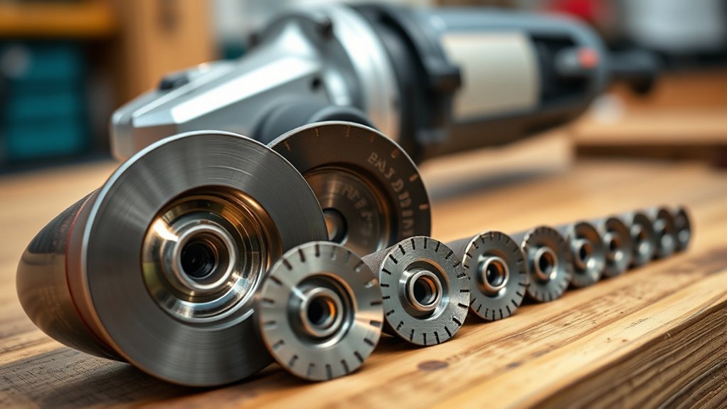
Angle grinder bore size is the diameter of the center opening in a wheel or disc. It must match the grinder’s complete mounting system—not just the visible spindle thread. On many conventional U.S. grinders, a 5/8-11 threaded spindle works with a 7/8-inch straight-hole wheel because the inner flange centers the wheel.
Quick Answer
An angle grinder wheel’s bore must match the tool’s approved mounting interface. A 7/8-inch bore is common on many 4-1/2-inch and 5-inch straight-hole wheels, while 5/8-11 usually describes a threaded spindle or hub. Verify the manual, wheel diameter, maximum RPM, guard, flanges, and wheel type before mounting.
Key Takeaways
- The wheel has a bore; the grinder has a spindle, flange system, or quick-change interface.
- A 7/8-inch wheel bore and a 5/8-11 spindle thread can be correct together on a conventional grinder.
- Never use a loose reducer, homemade washer, or improvised adapter on a handheld grinder.
- Bore size alone does not prove compatibility. Diameter, RPM, wheel type, guard, flanges, and material rating must also match.
- Stop immediately if a newly mounted wheel wobbles, rubs the guard, fails to seat flat, or produces unusual vibration.
At a Glance
| Time Required | 5–10 minutes |
| Difficulty | Easy, but safety-critical |
| Tools Needed | Grinder manual, wheel label or packaging, and an optional digital caliper |
| Cost | Usually $0 if the correct mounting hardware is already with the grinder |
Warning: Disconnect the plug or remove the battery before touching the wheel. Use the correct guard and side handle, wear eye and face protection, and never force a wheel onto the spindle or modify its center hole.
What You Need to Know About Bore Size in Angle Grinders
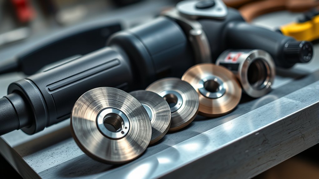
The bore size is the measured diameter of a wheel’s center opening. It is only one part of the connection between the accessory and the grinder. The tool may also use an inner flange, a lock nut, a threaded hub, or a proprietary quick-change mount.
On a common conventional setup, the inner flange has a raised shoulder that centers a straight-hole wheel. The lock nut then clamps the wheel against the flange. This is why a grinder with a 5/8-11 spindle thread can correctly use a wheel marked with a 7/8-inch bore.
- Wheel bore: The center opening in a non-threaded wheel, such as 22.23 mm (7/8 inch).
- Spindle thread: The grinder’s threaded shaft specification, such as 5/8-11 UNC or M14.
- Flange register: The raised part of the inner flange that centers a straight-hole wheel.
- Threaded hub: A factory-installed threaded insert that lets an accessory screw directly onto a compatible spindle.
- Quick-change interface: A keyed system such as X-LOCK that uses its own approved accessories.
Note: Product listings sometimes use “arbor size” for the wheel bore and sometimes for the grinder spindle. Read the full specification instead of relying on that word alone.
Why Matching Bore Size Matters for Safety
A correctly mounted wheel sits flat, is centered by the proper flange or interface, and is clamped with the hardware specified by the grinder manufacturer. OSHA states that grinding wheels must fit freely on the spindle and retain controlled clearance so mounting pressure and spindle expansion do not stress the wheel. See 29 CFR 1910.215(d)(2).
OSHA’s separate portable powered-tool regulation addresses guarding for portable abrasive wheels. The correct guard must remain installed and positioned between the operator and the wheel.
Correct mounting helps:
- Keep the wheel centered and reduce avoidable vibration.
- Prevent point loading around the center hole.
- Allow the flanges to clamp the wheel across the intended bearing surfaces.
- Keep the wheel inside the correct guard envelope.
- Reduce the chance of wheel damage, loss of control, or fragment impact.
A wheel is compatible only when its mount, diameter, speed rating, guard, flanges, wheel type, and intended material all match the grinder.
Common Angle Grinder Bore Sizes and Mounting Systems
There is no single bore size that fits every angle grinder. The examples below are common, but the grinder manual and accessory label are the final authority.
| Mount or Size | Where It Appears | What to Check |
|---|---|---|
| 22.23 mm (7/8-inch) straight hole | Common on many conventional 4-1/2-inch and 5-inch grinding, cut-off, flap, and diamond accessories. A Makita 4-1/2-inch/5-inch grinder manual shows 22.23 mm wheels installed with the specified inner flange and lock nut. | Correct flange shoulder, lock-nut orientation, guard, wheel diameter, and RPM. |
| 5/8-11 threaded spindle or hub | Common on many North American grinders and hubbed accessories. For example, this DEWALT grinder specifies a 5/8-11 spindle thread. | The accessory must have a factory-made matching thread or use the exact flange hardware named in the manual. |
| M14 threaded spindle | Common on many metric-market grinders. A Bosch 125 mm grinder lists an M14 spindle thread and a 22.23 mm bore specification together. | Do not confuse the M14 spindle thread with the wheel’s 22.23 mm center hole. |
| X-LOCK or another proprietary mount | Quick-change grinders that lock accessories into a keyed interface without a conventional flange nut. Bosch explains the X-LOCK grinder and accessory system. | Use accessories specifically marked compatible with the tool’s interface. |
| 16 mm, 20 mm, 25.4 mm (1 inch), and other sizes | Found on certain compact tools, diamond blades, specialty accessories, and other machines. | Use only when the grinder and guard are designed for that exact accessory. |
Bore Size vs. Arbor Size: What’s the Difference?
Bore size is the diameter of the wheel’s center opening. Spindle size describes the grinder’s shaft or thread. Arbor size is less precise because sellers may use it for either one.
For a straight-hole wheel, the bore normally fits over the raised register on the correct inner flange rather than matching the spindle thread diameter. For a threaded-hub accessory, the internal thread must match the spindle thread exactly. For an X-LOCK grinder, the keyed interface—not a conventional bore-and-nut arrangement—controls compatibility.
Pro Tip: When shopping, search by the grinder’s model number plus the accessory type. Then confirm every specification on the manufacturer page or manual instead of matching only one number.
How to Measure and Identify the Correct Bore Size
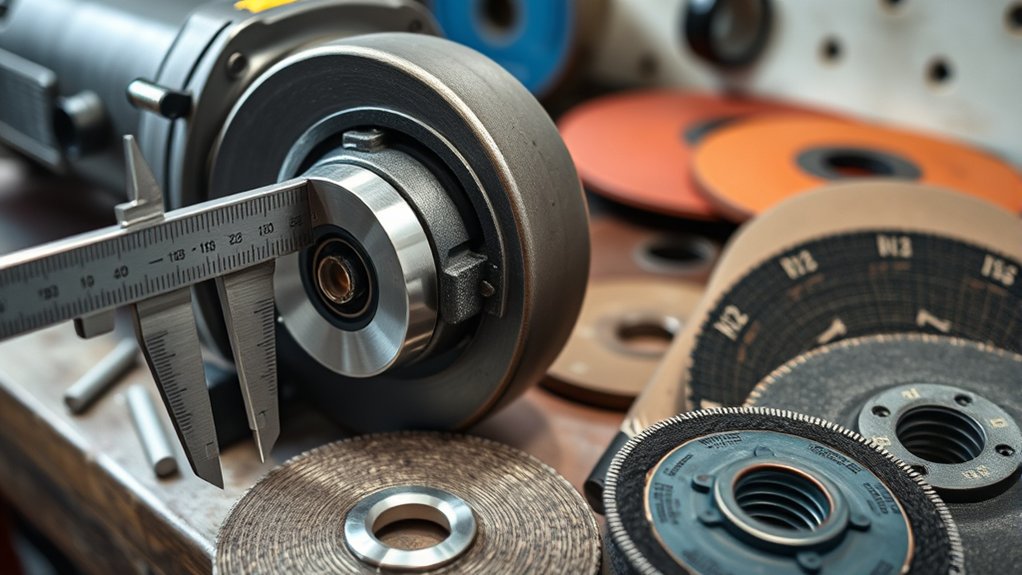
The wheel has the bore, so you are measuring the disc’s center opening, not “the grinder’s bore.” In most cases, reading the manual and wheel label is safer and more reliable than measuring.
Measuring Tools Required
- Grinder manual or official product page: Confirms the approved wheel diameters, spindle or interface, guards, and mounting hardware.
- Wheel label or packaging: Shows diameter, thickness, bore or thread, wheel type, material, and maximum RPM.
- Digital caliper: Useful when a plain center hole is unmarked and undamaged.
- Ruler: Suitable only for a rough check; it is not precise enough for final identification.
- Thread gauge: Useful for identifying an unmarked threaded spindle or hub, but the result must still be checked against the manual.
- Marker or notepad: Optional for recording measurements; it is not needed to find the widest point of a round bore.
Steps for Accurate Measurement
- Disconnect power. Unplug a corded grinder or remove the battery.
- Find the grinder model number. Check the nameplate, then read the manufacturer’s manual.
- Inspect the mounting system. Identify the inner flange, lock nut, threaded spindle, integrated hub, or quick-change interface.
- Read the wheel markings. Look for wheel diameter, bore or thread, maximum RPM, wheel type, and intended material.
- Measure only when needed. Use the inside jaws of a caliper across the center opening. Do not use a damaged or worn bore as a reliable reference.
- Cross-check the result. A measurement is not approval. The wheel must still be listed as compatible with the grinder and mounting hardware.
How to Select the Right Disc Based on Bore Size
Choosing a disc by bore size alone is unsafe. Use the following compatibility check before purchasing or mounting any accessory.
Products Worth Considering


PREMIUM QUALITY: These angled flap discs, also known as cut off wheels 4 1/2 inch, are constructed with industrial grade premium zirconia abrasive for strength, durability, and extended disc life as it holds up to high temperatures and pressure.
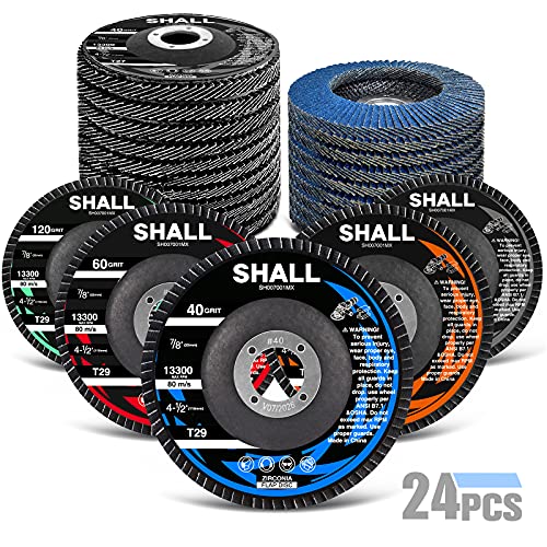
Extreme Durability and Value : Made of hard zirconia alumina material which lasts longer than standard aluminum oxide abrasive material; These flap discs also feature durable fiberglass backing plates requiring less pressure for heavy stock removal and provides with extra secure safe assurance - absorbing vibrations without smear during usage
Understanding Bore Size Compatibility
- Wheel diameter: The grinder and installed guard must be rated for that diameter.
- Mounting interface: Match the straight-hole bore and flange register, the threaded hub and spindle, or the proprietary quick-change system.
- Maximum speed: The wheel’s marked maximum RPM must be equal to or higher than the grinder’s maximum no-load speed.
- Wheel type: Use grinding wheels for grinding and cut-off wheels for cutting. Never side-grind with a cut-off wheel.
- Guard type: Use the guard specified for the wheel. Thin cut-off wheels commonly require a cut-off guard rather than an open grinding guard.
- Material rating: Choose a wheel made for the work material, such as carbon steel, stainless steel, masonry, tile, or concrete.
- Mounting hardware: Use the correct inner flange, outer flange or lock nut, orientation, and any manufacturer-specified spacers.
Measuring Disc Bore Diameter
Place the caliper’s inside jaws against opposite sides of the clean, undamaged center hole and read the diameter. A result near 22.23 mm indicates a nominal 7/8-inch bore. A measurement near 15.9 mm does not automatically mean the disc fits a 5/8-11 spindle; the accessory may require a threaded hub or a different flange arrangement.
Do not enlarge a small bore, grind the center hole, stack washers, or rely on a lock nut to center an incorrect wheel.
Choosing Appropriate Adapter Rings
A reducing bushing can be safe only when it is designed for the wheel and supplied or specifically recommended by the wheel or machine manufacturer. Norton’s summary of ANSI B7.1 states that separate reducing bushings should not be used to adapt larger-hole wheels to portable handheld tools unless the abrasive-wheel manufacturer supplies or recommends them. See Reducing Bushings—Know the Rules.
- Never use a loose hardware-store washer, homemade sleeve, shim stock, tape, or 3D-printed insert.
- Do not choose a reducer merely because it is made of steel or feels tight.
- A bushing must not project beyond the wheel faces or interfere with the flanges.
- Do not use a reducer to mount a wheel larger than the grinder or guard allows.
- A factory-installed threaded hub is not the same thing as a loose reducing ring.
Warning: If the wheel requires an unapproved adapter to fit, it is the wrong wheel for that grinder. Replace it with an accessory made for the tool’s mounting system.
How to Mount and Check an Angle Grinder Wheel
- Disconnect the grinder. Remove the battery or unplug the cord.
- Inspect the wheel. Do not use a cracked, chipped, dropped, wet, contaminated, past-dated, or otherwise damaged abrasive wheel.
- Inspect the tool hardware. Clean the spindle, flange faces, guard, and lock nut. Replace bent, worn, cracked, or missing parts.
- Install the correct guard and side handle. Position the closed side of the guard between you and the wheel.
- Mount the wheel exactly as shown in the manual. Use the specified flange faces and lock-nut orientation for the wheel type and thickness.
- Tighten with the supplied method. Do not use an impact wrench or add excessive leverage unless the manufacturer specifically calls for it.
- Hand-check clearance. Rotate the wheel by hand to confirm it does not touch the guard or tool.
- Run a no-load test. With the guard installed, stand out of the wheel’s plane, start the grinder in a clear area, and stop immediately if you see wobble or feel unusual vibration.
The Norton Angle Grinder Safety Basics guide also stresses correct wheel speed, guards, side handles, PPE, and products designed specifically for angle grinders.
What Happens If You Use the Wrong Bore Size?
- Bore too small: The wheel will not seat on the flange register. Forcing or modifying it can crack or weaken the wheel.
- Bore too large for the approved register: The wheel may not center correctly and can wobble or be clamped unevenly.
- Wrong threaded hub: The accessory may bind, cross-thread, fail to seat, or have inadequate thread engagement.
- Wrong flange or nut orientation: The wheel may be clamped on the wrong surfaces or the nut may bottom out before securing it.
- Wrong diameter or guard: The wheel may contact the guard, exceed the protected area, or run at a speed the wheel was not designed to handle.
Do not keep tightening a wheel that will not seat flat. Remove it, inspect the parts, and compare the setup with the grinder manual.
Troubleshooting Wheel Fit and Wobble
- The wheel is loose before the nut is installed: Some clearance is normal on a straight-hole wheel, but the correct flange register must center it and the specified nut must clamp it flat.
- The lock nut reaches the end of the threads: The nut may be reversed, the wrong nut may be installed, a flange may be missing, or the accessory may be too thin for that setup.
- The wheel wobbles after tightening: Stop. Check for debris, a damaged wheel, an incorrect bore, a reversed flange, bent hardware, or an accessory not approved for the grinder.
- The wheel rubs the guard: Confirm the wheel diameter, guard type, guard position, flange stack, and wheel shape.
- A threaded accessory stops before seating: Do not force it. Confirm the thread diameter, pitch, direction, and shoulder clearance.
- The mounting system is unknown: Do not run the grinder until the model-specific manual identifies the correct parts and accessory types.
Tips for Finding Compatible Discs for Your Bore Size
- Start with the exact grinder model number rather than a guessed spindle measurement.
- Use the manufacturer’s accessory chart or manual to identify approved diameters and mount types.
- Check all wheel markings before purchase: diameter, thickness, bore or thread, maximum RPM, wheel type, and material.
- Use the guard and mounting hardware required for that specific accessory.
- Keep the original flanges and lock nut with the grinder; do not mix similar-looking hardware from another tool.
- Inspect the center hole, hub, flanges, and spindle whenever a wheel begins to vibrate or no longer seats normally.
Products Worth Considering

[High-Performance Cutting] Designed for cutting metal & stainless steel, these cut off wheels 4 1/2 inch work efficiently with any angle grinder wheel, supporting speeds up to 13,300 RPM.

APPLICATION – GRAFF circular saw blade is suitable for cutting wood, plywood, drywall, MDF, plastic and all other non-metallic materials.
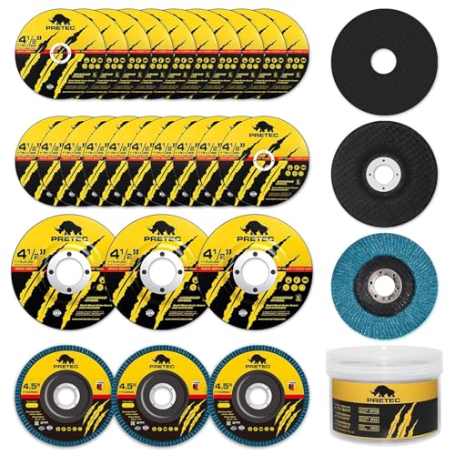
26pcs Angle Grinder Disc 4-1/2 inch & 3 Different Types : ✅ The 26 packs angle grinder wheels 4-1/2 inch including 20 Packs 4.5"x1/4"x7/8" Cut off Wheels, 3 Packs 4.5"x7/8" 60 Grit Flap Discs, 3 Packs 4.5"x1/25"x7/8" Grinding Wheels, with each type of disk collectively wrapped with those of its kind. This kit has everything you need to prep steel.
Bore Size Compatibility Checklist
Before operating the grinder, confirm all of the following:
- The accessory is made for an angle grinder and for the intended task.
- The wheel diameter and thickness are allowed by the grinder and guard.
- The bore, thread, or quick-change interface matches the approved mounting system.
- The wheel’s maximum RPM equals or exceeds the grinder’s maximum speed.
- The correct guard, inner flange, lock nut, and orientation are installed.
- The wheel sits flat, turns freely by hand, and does not touch the guard.
- The no-load test produces no wobble, rubbing, or unusual vibration.
How to Keep Your Grinder Running Smoothly
- Clean dust and debris from the spindle, flange faces, guard, and ventilation openings after use.
- Inspect the cord or battery connection, side handle, guard clamp, spindle lock, and mounting hardware regularly.
- Store wheels flat and dry according to the wheel manufacturer’s instructions.
- Do not use a wheel after it has been dropped or damaged.
- Replace worn, distorted, cracked, or missing flanges and nuts with model-correct parts.
- Investigate any new vibration before continuing work.
Frequently Asked Questions
What is the bore size on an angle grinder?
The bore belongs to the wheel, not the grinder. Many conventional 4-1/2-inch and 5-inch straight-hole wheels use a 22.23 mm (7/8-inch) bore, but grinders may use a 5/8-11 spindle, an M14 spindle, X-LOCK, or another system. Check the model-specific manual.
Can I use a 4.5-inch blade on a 5-inch grinder?
Only when the grinder manufacturer lists 4-1/2-inch accessories for that model and the mount, guard, wheel type, thickness, and RPM all match. A matching bore by itself is not enough. Never remove or defeat the guard to make a smaller or different wheel fit.
What size disc should I use for my angle grinder?
Use a disc diameter, thickness, mount, and wheel type specifically approved for the grinder and its guard. The wheel’s maximum RPM must be at least as high as the grinder’s maximum no-load speed, and the abrasive must be rated for the material and operation.
What does disc bore size mean?
Disc bore size is the diameter of the center opening in a non-threaded disc. That opening normally fits the centering register on the grinder’s approved inner flange. Threaded-hub and quick-change accessories use different mounting details.
Is a 5/8-11 spindle the same as a 5/8-inch wheel bore?
No. The “5/8-11” marking describes a 5/8-inch-diameter thread with 11 threads per inch. A plain 5/8-inch center hole is not automatically compatible. Many conventional grinders with 5/8-11 spindles use 7/8-inch straight-hole wheels centered by the inner flange.
Can I use a reducing ring on a handheld angle grinder?
Only when the reducing bushing is supplied or specifically recommended by the wheel or grinder manufacturer for that portable setup. Do not use loose universal reducers, washers, shims, tape, or homemade sleeves.
Why does a 7/8-inch wheel fit a grinder with a 5/8-11 spindle?
On many conventional grinders, the 7/8-inch wheel fits over a raised shoulder on the inner flange. The flange centers the wheel, while the lock nut threads onto the 5/8-11 spindle and clamps the wheel. Use only the flange and nut specified for the grinder.
Conclusion
Bore size matters, but it is not a stand-alone fit test. A safe angle grinder setup requires the correct mounting interface, wheel diameter, RPM rating, wheel type, guard, flanges, and intended material. Read the grinder manual and wheel markings, use only approved mounting parts, and stop if the wheel does not seat flat or runs with vibration. For a compact safety reminder, review OSHA’s Abrasive Wheel Grinder Safety QuickCard.
Sources
- OSHA 29 CFR 1910.215—Abrasive Wheel Machinery — wheel fit, controlled clearance, flanges, inspection, and RPM requirements.
- Makita XAG04 Instruction Manual — 22.23 mm wheel mounting, flange orientation, guards, and operating checks.
- Norton Abrasives: Reducing Bushings—Know the Rules — restrictions on bushings for portable handheld tools.
- Norton Abrasives: Angle Grinder Safety Basics — wheel speed, PPE, guards, side handles, and mounting safety.
- Bosch X-LOCK Angle Grinders — proprietary quick-change mounting compatibility.
- Bosch GWS 14-125 S Technical Data — example of an M14 spindle used with a 22.23 mm wheel bore specification.