
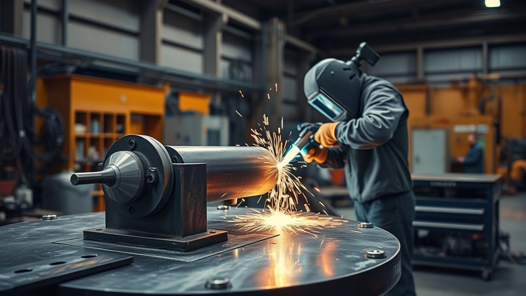
A welding positioner is a fixture, often powered, that rotates and tilts a workpiece so you can weld from a safer and more controlled angle. Instead of forcing your body around the part, you bring the joint into a better welding position. That can improve torch access, bead control, penetration consistency, and repeatability when the positioner is correctly sized, clamped, grounded, and operated.
Quick Answer
A welding positioner holds, rotates, and tilts a workpiece so the weld joint stays at a better angle. It helps you control the weld pool, keep a steadier torch position, reduce awkward reaching, and improve repeatability. Choose one by rated load, center of gravity, table size, rotation speed, tilt range, and welding-current capacity.
Key Takeaways
- A welding positioner improves access by moving the workpiece instead of forcing you into awkward welding positions.
- The biggest selection factors are rated capacity, center of gravity, fixture weight, rotation speed, tilt range, and secure clamping.
- Never exceed the manufacturer’s load rating, and do not use bearings, chains, hoists, or unintended metal paths to carry welding current.
- Positioners can support MIG, TIG, stick, flux-core, pipe welding, and robotic welding when the model is matched to the process.
- Good setup matters as much as the machine: inspect the unit, clamp the part, dry-run the rotation, attach the work lead correctly, and wear proper PPE.
At a Glance
| Time Required | About 5 to 15 minutes for a basic setup after installation; longer for heavy parts, custom fixtures, or robotic cells. |
| Difficulty | Moderate. The hard part is not pressing the controls; it is balancing, clamping, grounding, and confirming safe clearance. |
| Tools Needed | Rated positioner, approved clamps or fixture, welding machine, work lead, PPE, tape measure, square, and the manufacturer’s manual. |
| Cost | Varies widely by load rating, table size, speed control, tilt range, automation features, and whether the unit is bench-top or industrial. |
What Is a Welding Positioner?
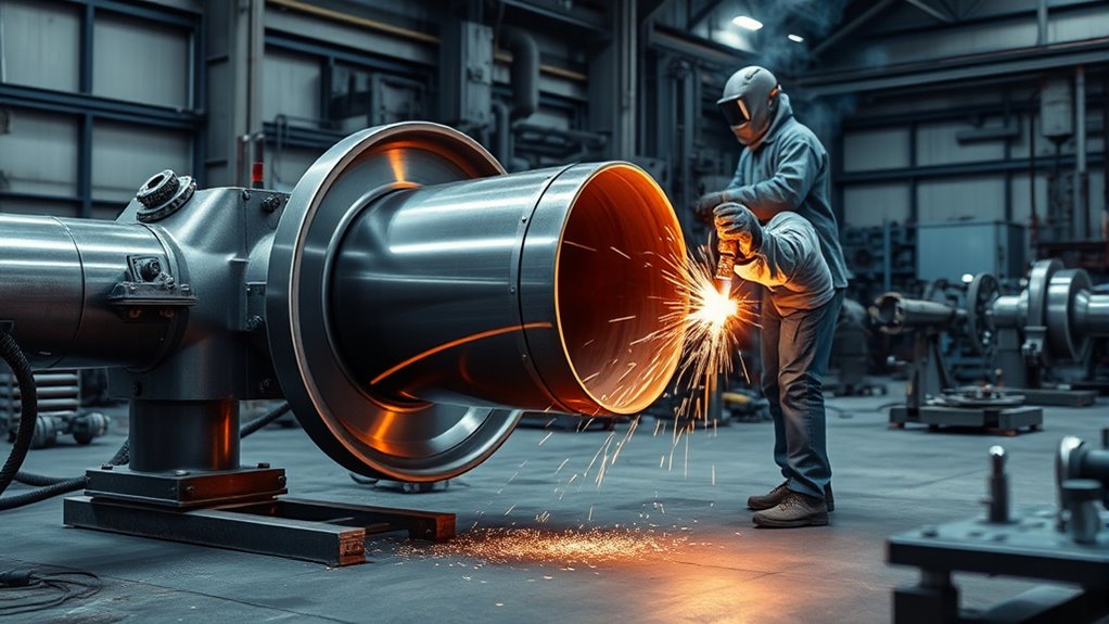
A welding positioner is a workholding machine that supports a part and changes its angle during welding. Most units use a powered table, chuck, headstock, or rotating fixture. Some also tilt, index, or coordinate with robotic equipment.
The main purpose is simple: keep the weld joint where you can see it, reach it, and control it. That matters because torch angle, travel speed, stickout, puddle visibility, and body position all affect weld quality.
A positioner does not make a bad setup safe. It makes a good setup easier to control, repeat, and inspect.
You can use a positioner for small brackets, pipe sections, flanges, round parts, tanks, frames, or heavier assemblies. The right model depends on the part’s weight, shape, center of gravity, and the weld process you plan to use.
How Welding Positioners Work
Welding positioners work by holding the workpiece on a rotating or tilting platform. You clamp the part to the table, chuck, faceplate, or custom fixture, then use a control, foot pedal, pendant, or automation system to move the part.
On a simple rotary table, the part spins around one axis. On a tilt-turn model, the table can rotate and tilt so you can bring the joint into a flat or near-flat welding position. Many tilt models allow movement up to 90 degrees, but the exact tilt range depends on the machine.
Good positioners provide smooth motion. Smooth rotation helps you keep a consistent travel speed and torch angle, especially on round welds, circumferential pipe joints, collars, and repetitive production parts.
Some machines include variable speed control, forward and reverse rotation, digital speed readouts, indexing, programmable motion, or integration with robotic welding cells. A basic shop unit may only need a foot pedal and speed knob, while a production cell may need synchronized motion with the welding torch.
Note: The positioner’s rated capacity is not just the weight of the part. Fixture weight, offset load, and center of gravity also count.
Why Weld Position Matters
You need to control weld position because gravity changes how molten metal behaves. A flat or well-supported position usually gives you better puddle control than an overhead or awkward vertical position.
When the workpiece is correctly oriented, you can reach the joint, see the puddle, hold the right torch angle, and reduce stops caused by repositioning. That can improve consistency and reduce rework.
Gravity’s Effect On Welds
Gravity pulls on the molten weld pool. In flat welding, that pull is easier to manage. In vertical and overhead welding, the pool can sag, drip, or become harder to shape. That is one reason positioners are valuable for round parts and repetitive joints.
Research on weld-pool behavior shows that welding position can change pool shape and flow patterns. In practice, that means the same settings may behave differently when the joint angle changes.
A positioner helps by turning the workpiece so gravity works with you instead of against you. You still need correct amperage, travel speed, filler control, shielding, and joint preparation.
Better Access, Better Quality
Better joint access makes it easier to maintain a steady arc. You can position your body closer to neutral, reduce shoulder strain, and avoid reaching around corners or under the part.
That access also helps you track the seam, keep the contact tip or tungsten at the right distance, and make cleaner starts and stops. For repetitive work, the positioner helps each part begin from the same orientation.
The result can be more uniform bead shape, better penetration control, and fewer defects, but only when the part is clamped securely and the motion speed is matched to the weld process.
Safer Welding Positions
Welding in a stable, visible position is safer than welding while twisted, reaching, or leaning under a part. Ergonomic guidance from NIOSH explains that awkward postures, force, and repeated motions can contribute to work-related musculoskeletal disorders.
A positioner can reduce those exposures by bringing the joint to you. It can also reduce manual lifting and repeated part handling when used with the right fixtures, hoists, and workflow.
Warning: A rotating workpiece can pinch, crush, or throw a poorly clamped part. Keep hands, sleeves, cables, and torch leads clear of the rotation path before pressing the control.
Main Types of Welding Positioners
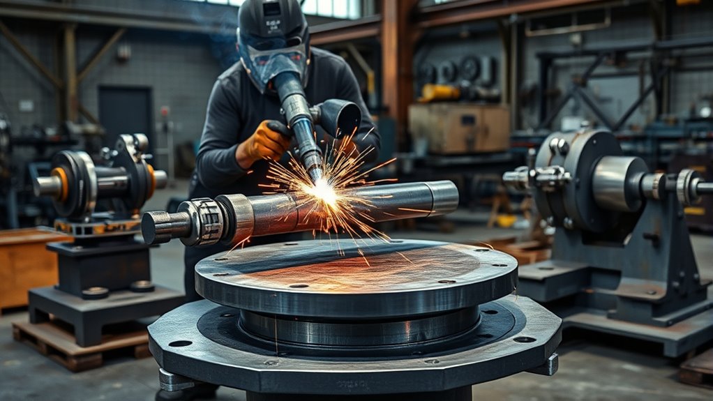
Welding positioners come in several configurations. The best choice depends on part size, weld location, load balance, and whether you are doing one-off fabrication or repeat production.
| Positioner Type | Best Use | Main Advantage |
| Rotary table | Small to medium parts, circular welds, brackets, flanges | Simple rotation and compact footprint |
| Tilt-turn positioner | Parts that need angle changes during setup | Better access to multiple joint faces |
| Headstock-tailstock | Long shafts, beams, frames, tanks, pipe sections | Supports long work at both ends |
| H-frame | Larger industrial assemblies and robotic cells | Strong support and multi-part handling |
| Ferris wheel | High-volume production with separate load and weld zones | Keeps welding and loading areas organized |
| Pipe positioner or pipe rotator | Pipe, tube, vessels, and round workpieces | Stable rotation for circumferential welds |
Products Worth Considering

Smooth Rotation: VEVOR rotary welding positioner boasts 80W high quality motor that runs at 1-12 rpm low speed for stable and smooth operation. With a load capacity of up to 33.1 lbs/15kg (vertical) or 66.1lbs/30 Kg (horizontal), it offers excellent stability and supports efficient, precise welding.

Smooth Rotation: VEVOR rotary welding positioner boasts 20W high quality motor that runs at 1-12 rpm low speed for stable operation. With a load capacity of up to 11lbs/5 Kg (vertical) or 22lbs/10 Kg (horizontal), it offers excellent stability and supports efficient, precise welding.

Stable and Powerful Motor: VEVOR’s rotary welding positioner is equipped with a high-quality 120W motor, providing a low-speed range of 0.5-6 rpm. This ensures stable and smooth operation for precise welding tasks. The positioner offers excellent stability with a vertical load capacity of up to 55 lbs (25 kg) and a horizontal load capacity of 110 lbs (50 kg).
Rotary Table and Headstock Positioners
Rotary table and headstock units are the two styles many welders see first. A rotary table is compact and useful for smaller parts. A headstock or headstock-tailstock system is better when the workpiece is long, heavy, or needs support across its length.
Rotary Table Uses
A rotary table positioner rotates the workpiece on a flat table or faceplate. You may attach the part with clamps, T-slots, a chuck, a fixture plate, or a custom jig.
Use a rotary table for round welds, small production parts, collars, flanges, rings, fittings, brackets, and parts that need a steady spin. Some models let you load one part while another is being welded, but that depends on the machine layout.
The biggest benefit is consistency. Instead of walking around the part, you can keep your torch hand steady while the joint moves through the arc.
Headstock Positioner Benefits
A headstock positioner rotates the part from one driven end. A headstock-tailstock setup supports the opposite end, which makes it better for long or heavy workpieces.
This setup is useful for tanks, beams, frames, long pipe sections, shafts, and assemblies that would be unstable on a small table. It lets you rotate the work under controlled conditions while keeping the load supported.
For best results, check the rated capacity, center height, fixture length, tailstock adjustment range, and whether the system has the welding-current capacity needed for your process.
Best Applications For Each
Choose a rotary table when the part is compact, balanced, and easy to clamp on a table. Choose a headstock-tailstock unit when the work is long, uneven, or needs support across two points.
- Use a rotary table for small round parts, short-cycle jobs, bench work, and repeated welds.
- Use a tilt-turn positioner when the joint face changes and you need better access to several sides.
- Use a headstock-tailstock unit for long shafts, pipe sections, frames, and heavy assemblies.
- Use a pipe rotator when the part is cylindrical and needs steady circumferential rotation.
H-Frame and Ferris Wheel Positioners
H-frame and ferris wheel positioners are common in larger production environments. They are built for heavier parts, repeated cycles, and organized flow between loading and welding zones.
An H-frame positioner uses a strong frame to hold one or more workpieces. This gives the system good support for large assemblies and robotic welding cells. It can also allow one part to be welded while another part is prepared, depending on the configuration.
A ferris wheel positioner separates load and weld stations. One side can be prepared while the other side is welded. This helps reduce idle time and keeps operators farther from the active weld zone when the cell is properly guarded.
These systems are not usually the first choice for a small shop. They make the most sense when repeatability, throughput, robotic access, and part flow justify the floor space and cost.
Key Benefits of Welding Positioners
Welding positioners can improve precision, safety, comfort, and output. The gains are strongest when the same welds repeat across many parts.
By rotating the workpiece, you can keep the torch angle steadier and reduce manual resets. That helps control bead width, travel speed, penetration, and heat input.
By tilting the workpiece, you can bring difficult joints into view. This is especially useful when you would otherwise weld overhead, reach around a corner, or stop repeatedly to roll the part by hand.
Positioners also support automation. Robotic and mechanized welding depend on repeatable part location, controlled movement, and predictable torch-to-work distance. Research on pipe-welding automation has shown that controlling electrode orientation, welding speed, and distance from the work can improve weld quality.
Pro Tip: Before welding, run the positioner through the full rotation without an arc. Watch for cable pull, clamp interference, part wobble, and anything that could strike the torch or fixture.
Common Welding Positioner Drawbacks
Welding positioners have real advantages, but they are not the right answer for every job.
The first drawback is cost. A small bench unit is much cheaper than a heavy industrial or robotic system, but prices vary widely by load rating, controls, table size, and automation features.
The second drawback is space. Even a compact positioner needs clearance for rotation, tilt, cables, clamps, and part loading. Larger systems may need a planned workcell, guarding, hoist access, and trained operators.
The third drawback is setup time. For one quick weld, clamping and balancing the part may take longer than welding it by hand. For repeated parts, that setup time often pays off.
The fourth drawback is misuse risk. A positioner can tip, stall, overload, pinch, or lose the part if the workpiece is too heavy, poorly centered, or badly clamped.
Advanced systems may also require programming, calibration, maintenance, and troubleshooting. If you use a robotic cell, you must also consider torch access, collision avoidance, guarding, and emergency stops.
How to Use a Welding Positioner Safely
To use a welding positioner safely, follow a setup process instead of clamping and welding by instinct.
- Read the manual. Check the rated capacity, duty limits, table angle limits, current capacity, controls, and maintenance requirements.
- Place the unit on a stable surface. Use a flat floor, bench, or foundation that can support the positioner, fixture, and workpiece.
- Confirm the load. Include the workpiece, chuck, clamps, fixture plate, and any added tooling in the total weight.
- Check center of gravity. A load that is off-center can overload the drive, reduce capacity, or cause tipping.
- Clamp the part securely. Use approved clamps, T-slots, chuck jaws, bolts, or fixtures. Do not rely on weight alone.
- Clear the rotation path. Keep leads, hoses, hands, clothing, and tools away from pinch points and moving parts.
- Attach the work lead correctly. Follow the welding machine and positioner instructions. Do not route welding current through bearings or moving parts unless the positioner is designed with a proper current collector.
- Dry-run the motion. Rotate and tilt the part through the full planned range before striking an arc.
- Wear proper PPE. Use welding helmet, gloves, flame-resistant clothing, eye protection for helpers, and ventilation or respiratory protection when needed.
- Stop if anything shifts. If the load moves, the motor strains, the fixture loosens, or the cables pull tight, stop and reset the job.
For hot work safety, follow your shop’s procedure and OSHA’s welding, cutting, and brazing general requirements. OSHA guidance covers fire prevention, eye protection, protective clothing, ventilation, confined-space issues, and fire-watch conditions.
For arc welding equipment, OSHA’s arc welding and cutting standard covers grounding, work leads, machine hookup, and the need to follow manufacturer instructions.
Warning: Do not weld if the part weight is unknown, the center of gravity is unstable, the clamps are damaged, the positioner is overloaded, or the work lead would force current through unintended machine parts.
How to Choose the Right Positioner
Choosing the right welding positioner starts with the part, not the machine. Measure the workpiece, estimate the fixture weight, and decide which welds need rotation or tilt.
Products Worth Considering

High Load Capacity: This rotary welding positioner supports up to 661 lbs horizontally and 331 lbs vertically. The premium carbon-steel construction ensures stable performance during heavy-duty welding tasks

【🎯PRECISION CLAMPING】Equipped with a 2.56" 3-jaw lathe chuck, this automatic welding turntable securely holds round workpieces from 0.08" to 2.28", eliminating manual adjustments and providing steady hands-free operation for flawless MIG/TIG seams.

Compact and Portable with a 180mm Diameter Working Table: Weighing just 9kg, this portable turntable is easy to move and set up. The 180mm diameter working table with a 220mm height provides ample space for a variety of welding projects while maintaining stability and durability.:
Workpiece Size And Weight
Start with total load. That includes the part, clamps, chuck, fixture plate, and any temporary supports. Then check how far the load sits from the table face or rotation axis.
A centered load is easier for the positioner to handle. An off-center or overhung load creates more torque. That can reduce usable capacity even when the total weight seems within the rating.
Check the manufacturer’s capacity chart for horizontal and vertical loading. If the manual gives a center-of-gravity limit, follow it exactly. When the load is unusual, ask the manufacturer or a qualified engineer before welding.
Welding Method Compatibility
Match the positioner to the welding method. MIG and flux-core often need steady rotation and room for the gun, nozzle, and cable. TIG often needs very smooth low-speed rotation and fine foot-pedal or remote control. Stick welding needs good clearance, strong support, and easy access to change electrodes.
For pipe or tube work, look for smooth speed control, stable rollers or chucking, and enough clearance for purge lines if needed. For robotic welding, confirm robot reach, fixture repeatability, torch angle, guarding, and collision clearance.
Also check welding-current capacity. Some positioners include a grounding lug or current collector. Use it only as the manufacturer directs.
Workspace And Stability
Your positioner needs enough space to rotate the largest part without hitting the bench, torch, wall, operator, cables, gas hoses, or other equipment.
For heavy parts, plan how you will load and unload safely. You may need a hoist, forklift, crane, or lift table. Do not balance a heavy part by hand while trying to clamp it.
Stability matters during welding and during setup. A top-heavy load can shift before the arc ever starts. If the positioner has wheels, lock them or use the manufacturer’s recommended anchoring method.
Speed Control And Torque
Rotation speed should match the weld. Too fast and the bead narrows or loses fusion. Too slow and heat builds up, distortion increases, and the bead may become too wide.
Torque matters when the part is heavy or off-center. A positioner that can hold the part still may still struggle to start, stop, or rotate smoothly under load. If the motor stalls or surges during a dry run, do not weld until the setup is corrected.
Maintenance and Inspection Checklist
Treat positioner maintenance as part of welding safety. A worn or loose positioner can damage the part, ruin the weld, or create a serious hazard.
- Inspect power cords, foot pedals, pendants, and control cables for damage.
- Check clamps, bolts, T-slots, chuck jaws, and fixture plates before each setup.
- Look for table wobble, bearing play, loose fasteners, and abnormal noise.
- Keep the table face and clamp surfaces clean so parts seat flat.
- Check grounding or current-transfer points according to the manual.
- Lubricate gears, bearings, or slides only as the manufacturer recommends.
- Stop using the unit if it tips, stalls, sparks unexpectedly, overheats, or shows electrical damage.
When You Should Not Use a Positioner
Do not use a welding positioner just because one is available. Skip it or redesign the setup when the part cannot be secured, the load rating is uncertain, or the rotation path is blocked.
You should also avoid using a positioner when the workpiece contains flammable residue, trapped pressure, sealed cavities, or coatings that need special preparation. The CCOHS welding hazards overview notes that welding can involve fumes, gases, UV radiation, burns, electrical shock, fires, and explosions.
If the part is very large, irregular, or critical, get the setup reviewed by a qualified supervisor, engineer, or the equipment manufacturer before welding.
Frequently Asked Questions
What are the common problems with welding positioners?
Common problems include overloading, poor clamping, off-center loads, tipping, cable snagging, rough rotation, control issues, worn bearings, loose fasteners, and electrical current traveling through unintended parts. Most problems come from poor setup, not the positioner itself.
How do you use a welding positioner?
Place the positioner on a stable surface, confirm the load rating, clamp the workpiece securely, attach the work lead as instructed, clear the rotation path, dry-run the motion, set the speed, and weld while keeping hands, cables, and clothing away from moving parts.
Can a welding positioner improve weld quality?
Yes, it can improve weld quality when it helps you hold a steadier torch angle, travel speed, and joint position. It does not replace good fit-up, clean material, correct settings, shielding, or welder skill.
Do welding positioners work for MIG, TIG, and stick welding?
Yes. MIG and flux-core benefit from steady rotation and better gun access. TIG benefits from smooth low-speed control. Stick welding benefits from better joint access and less awkward body position. Always match the positioner’s current capacity and controls to the process.
What size welding positioner do I need?
Choose a positioner rated above the combined weight of the workpiece and fixture, with enough table size, torque, tilt range, and clearance for the job. Check the manufacturer’s center-of-gravity chart, not just the advertised weight rating.
Conclusion
A welding positioner helps you rotate, tilt, and support a workpiece so the weld joint sits in a better position. That can improve access, reduce fatigue, support safer posture, and make repeat welds more consistent. The key is choosing a unit that matches the part, then using it with secure clamping, correct work-lead placement, safe clearance, and regular inspection.
Sources
- OSHA 1910.252, General Requirements for Welding, Cutting, and Brazing — supports fire prevention, PPE, ventilation, and hot-work safety guidance.
- OSHA 1910.254, Arc Welding and Cutting — supports grounding, work-lead, machine hookup, maintenance, and manufacturer-instruction guidance.
- CCOHS Welding Overview of Types and Hazards — supports welding hazard and control information.
- NIOSH Ergonomics and Work-Related Musculoskeletal Disorders — supports ergonomic benefits and awkward-posture risk guidance.
- Design, Analysis, and Simulation of a Pipe-Welding Robot with Fixed Plinth — supports the importance of controlled electrode orientation, speed, and distance.
- The Effects of Process Parameters on Melt-pool Oscillatory Behaviour in Gas Tungsten Arc Welding — supports the effect of welding position on melt-pool behavior.




