Inductive loads can damage a circuit the moment you switch them off. Relays, motors, solenoids, and coils store energy in a magnetic field, then release it as a sharp voltage spike when current stops. Electronic kickback protection gives that energy a safe path, so your components last longer and your circuit runs with less electrical noise.
What’s in This Article
- What Is Electronic Kickback Protection and Why Is It Important?
- Understanding Inductive Kickback and Its Effects on Circuit Protection
- How Does Inductive Kickback Affect Your Circuit?
- Common Kickback Protection Methods
- How to Select the Best Kickback Protection Components for Your Circuit
- How to Implement Kickback Protection in Your Circuit Design
- Real-World Applications: Why Kickback Protection Is Crucial in Everyday Electronics
- What Is Next for Kickback Protection Technology?
- Frequently Asked Questions
- References
Quick Answer
Electronic kickback protection controls voltage spikes that appear when an inductive load turns off. Flyback diodes, resistor-capacitor snubbers, transient voltage suppressors, and metal oxide varistors help absorb or clamp those spikes. The right choice depends on your load current, switching speed, voltage rating, and how fast the load must turn off.
Key Takeaways
- Inductive loads create voltage spikes when current stops suddenly.
- Flyback diodes work well for many direct current relay, solenoid, and motor coil circuits.
- Snubbers, transient voltage suppressors, and varistors help when speed, alternating current, or higher energy matters.
- Each protection part must match the circuit voltage, load current, energy level, and switching pattern.
- Good grounding and short wiring paths reduce electromagnetic interference.
What Is Electronic Kickback Protection and Why Is It Important?

Electronic kickback protection prevents damage from voltage spikes that inductive loads create when you switch them off. These spikes can stress semiconductors, pit relay contacts, reset microcontrollers, and add electromagnetic interference (EMI) to nearby wiring.
Common protection methods include flyback diodes, resistor-capacitor (RC) snubber circuits, transient voltage suppressor (TVS) diodes, and metal oxide varistors (MOVs). Each option gives stored inductor energy a safer path or clamps the voltage before it reaches sensitive parts.
Without protection, you may see random resets, failed drivers, burned contacts, or noisy sensor readings. In industrial equipment, the same issue can raise maintenance costs and reduce operational safety.
Understanding Inductive Kickback and Its Effects on Circuit Protection
When current flows through an inductor, the magnetic field stores energy. When you interrupt that current, the inductor tries to keep current moving, so voltage rises until it finds a path.
That event causes inductive kickback. The spike may create arcing at switch contacts or stress components beyond their rated voltage.
Inductor Behavior During Interruption
Inductors play a key role in circuits that use relays, motors, transformers, and solenoids. When you open the circuit, the stored magnetic energy collapses and pushes current through any available path.
If you don’t provide a controlled path, the voltage can rise high enough to arc across contacts. It can also couple into nearby traces or wires and cause EMI.
| Effect | Cause | Mitigation |
|---|---|---|
| High voltage spikes | Current interruption | Flyback diodes or TVS diodes |
| EMI | Fast voltage change | Short wiring and proper grounding |
| Component damage | Overvoltage stress | Rated protection components |
| Arcing | Energy release across contacts | Snubbers or contact suppression |
Mitigating Kickback Risks
You can reduce kickback by placing a protection part close to the inductive load or switching device. Short paths matter because long leads add inductance and can still create sharp transients.
A flyback diode works well across many direct current (DC) coils. When the switch opens, the diode becomes forward biased and lets coil current decay safely.
RC snubbers, MOVs, and TVS diodes suit cases where you need faster release, alternating current (AC) operation, or stronger surge clamping. Choose the part based on the load, not just the supply voltage.
Warning: Use parts rated above your circuit’s expected voltage, current, and energy, or the protection part can fail short or open.
How Does Inductive Kickback Affect Your Circuit?
Inductive kickback can affect your circuit even when the main function still appears to work. A relay may click, a motor may spin, and a solenoid may move, but each switch-off event can slowly damage contacts or driver parts.
The spike can exceed the safe voltage of a transistor, metal oxide semiconductor field-effect transistor (MOSFET), microcontroller input, or integrated driver. It can also create EMI that causes false triggers in sensors and logic circuits.
Protective devices reduce these risks by routing or absorbing the stored energy. They also help your circuit behave in a more repeatable way during switching.
Common Kickback Protection Methods
You have several practical ways to protect a circuit from kickback. The best method depends on whether your load uses AC or DC, how much energy it stores, and how quickly it must turn off.
Flyback Diode Implementation
A flyback diode connects in parallel with a DC inductive load, usually across a relay coil or solenoid coil. The diode stays reverse biased while the coil receives power, so normal current flows through the load.
When the switch opens, the coil voltage reverses and forward biases the diode. Current then circulates through the coil and diode until the stored energy fades.
General-purpose rectifier diodes, such as parts in the 1N400x family, suit many low-speed relay and solenoid circuits. Faster switching circuits may need a fast recovery diode, Schottky diode, TVS diode, or a diode plus Zener clamp.
Pro tip: Place the flyback diode as close to the coil as practical to reduce loop area and electrical noise.
Relay-Based Disconnection Systems
Relay-based disconnection systems use electromechanical contacts to cut power to a load. Those contacts need protection because inductive kickback can cause arcing when they open.
A flyback diode across a DC relay coil protects the control side. For the switched load side, an RC snubber, MOV, or TVS diode may work better, especially when the relay controls a motor or transformer.
Choose relay contacts with enough voltage, current, and load-type ratings. Resistive load ratings do not always apply to motors, coils, or other inductive loads.
Circuit Design Considerations
Good circuit design starts with the load. Estimate the stored energy, steady current, supply voltage, switch type, and required turn-off time before you select protection.
A basic flyback diode clamps voltage low, but it can make a relay or solenoid release more slowly. A TVS diode or diode-Zener clamp allows a higher clamp voltage, so current decays faster.
Use short traces, solid ground returns, and rated components. These choices protect sensitive electronics and reduce EMI.
How to Select the Best Kickback Protection Components for Your Circuit

Select kickback protection by matching the part to the electrical stress it must handle. Check the load current, supply voltage, expected spike energy, switching speed, and ambient temperature.
For simple DC coils, start with a flyback diode rated for the coil current and reverse voltage. For faster release or higher performance switching, consider a TVS diode, a Zener clamp, or an RC snubber.
For AC loads, don’t use a single flyback diode across the load because it will conduct during part of the AC cycle. Use an RC snubber, MOV, bidirectional TVS device, or another AC-rated suppression method.
Note: A higher clamp voltage usually speeds up release, but every protected part must safely tolerate that voltage.
Products Worth Considering

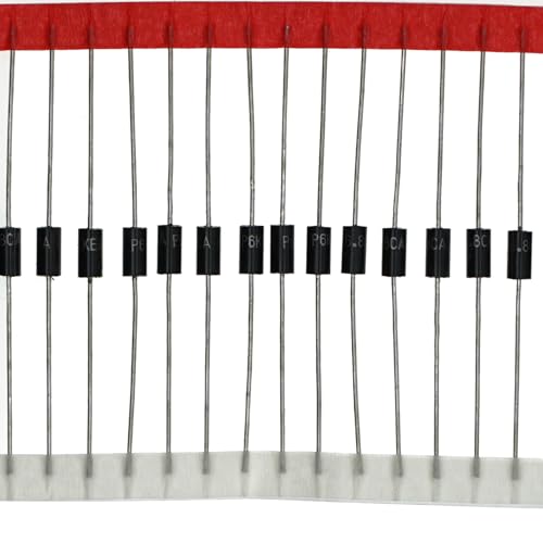
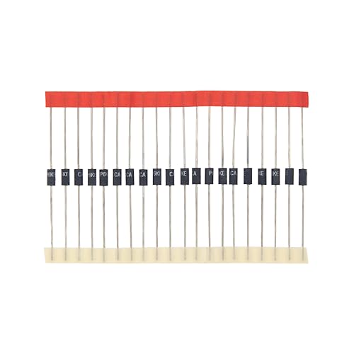
SMB 600W TVS Uni-Directional Diode Kit
How to Implement Kickback Protection in Your Circuit Design
Build kickback protection into the design before you test the first prototype. Retrofitting protection later can force layout changes, relay changes, or driver changes.
| Protection Method | Components Involved | Benefits |
|---|---|---|
| Flyback Diode | Diodes | Gives DC coil current a safe path |
| Snubber Circuit | Resistors, Capacitors | Absorbs voltage spikes and reduces ringing |
| Transient Voltage Suppressor (TVS) | TVS Diodes | Clamps voltage to a safer level |
| Metal Oxide Varistor (MOV) | Voltage-dependent resistors | Handles larger surge events in many AC circuits |
| Adequate Ratings | Rated components | Reduces the risk of component failure |
Place suppression parts near the coil, switch, or relay contacts that create the spike. Keep the current loop small, and avoid routing noisy switching paths near sensor or logic traces.
Test the circuit under the worst expected load conditions. Use an oscilloscope with proper probing technique to check the spike voltage, ringing, and switch stress.
Products Worth Considering
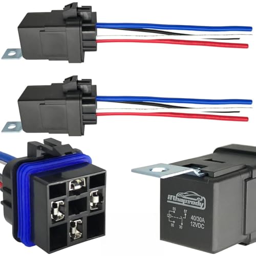
Note: Pin 86 connects to the positive pole, and Pin 85 connects to the negative pole
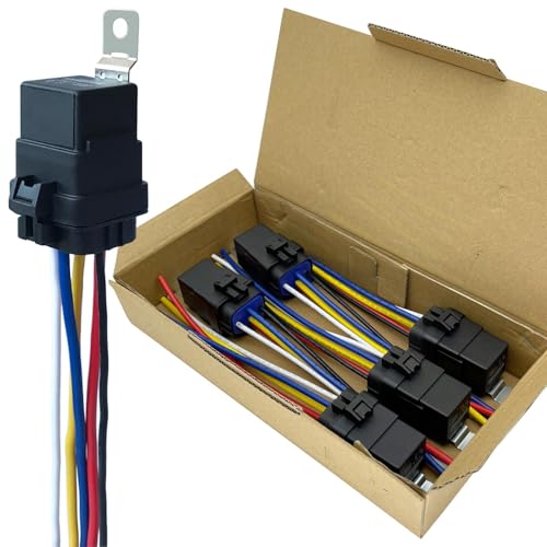
Note: Pin 86 connects to the positive pole, and Pin 85 connects to the negative pole

【30A/40A Relay】 - These 5 pin relays are rated at 12v 30A/40A (NO: 40A, NC: 30A), spdt heavy duty design built-in diode relay.
Real-World Applications: Why Kickback Protection Is Crucial in Everyday Electronics
You can find kickback risks in many everyday devices. Door locks, automotive relays, motor drivers, appliance controls, power tools, and industrial panels all use inductive loads.
In a small embedded system, one unprotected relay can reset a microcontroller or corrupt a sensor reading. In higher power equipment, repeated arcing can shorten relay life and raise fire or shock risks.
Power tools also use kickback protection in a mechanical safety sense. That tool safety feature differs from electrical inductive kickback, but both aim to reduce sudden, harmful events.
What Is Next for Kickback Protection Technology?

Kickback protection continues to improve as circuits become smaller, faster, and more connected. Newer drivers often include built-in clamp paths, diagnostic outputs, thermal shutdown, and fault reporting.
- Smarter sensing: Driver circuits can monitor current and voltage changes during switching.
- Faster protection: Modern TVS and driver clamp designs can react quickly to short transients.
- Better diagnostics: Connected tools and controllers can report faults before parts fail.
- Stronger integration: Integrated circuits can combine switching, protection, and reporting in one package.
These features don’t remove the need for good design. You still need correct ratings, layout, grounding, and testing.
Frequently Asked Questions
What Is Kickback Protection?
Kickback protection uses components or circuits to control voltage spikes from inductive loads. It protects switches, drivers, microcontrollers, and nearby circuits from damage or noise.
How Do You Protect Against Inductive Kickback?
You protect against inductive kickback by giving stored inductor energy a controlled path. Common options include flyback diodes, RC snubbers, TVS diodes, MOVs, and rated driver clamps.
What Are Three Common Methods of Electrical Kickback Protection?
Three common methods include flyback diodes, RC snubber circuits, and TVS diodes. MOVs also help in many AC and surge-prone circuits.
What Is a Kickback in Simple Terms?
A kickback is a sudden voltage spike that happens when current through a coil or motor stops. The inductor releases stored magnetic energy, and the voltage rises until the energy finds a path.
Can a Flyback Diode Slow Down a Relay or Solenoid?
Yes. A basic flyback diode clamps the voltage low, so coil current decays more slowly. If you need faster release, use a higher voltage clamp method that still stays within safe component ratings.
Conclusion
Electronic kickback protection keeps stored inductor energy from damaging your circuit. Start by identifying each relay, motor, solenoid, and coil, then choose protection that fits its voltage, current, and switching needs.
Use rated parts, short wiring paths, and proper grounding to reduce both failure risk and EMI. A protected circuit gives you more reliable switching, cleaner signals, and longer component life.
References
- Understanding Buck Power Stages in Switchmode Power Supplies — Texas Instruments
- Transient Voltage Suppression TVS Diodes Protection Principles — STMicroelectronics
- Varistor Basic Properties and Application — Littelfuse