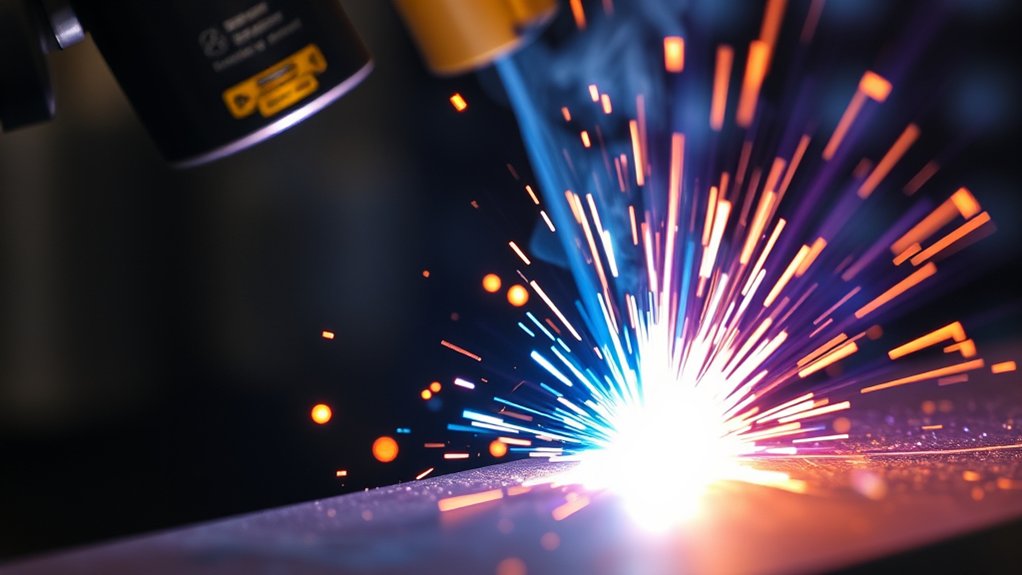
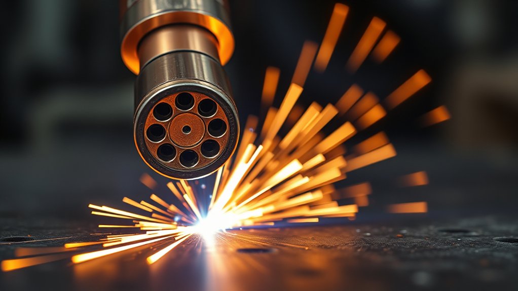
You’re dealing with an arc that routinely reaches about 50,000°F (≈28,000°C), with typical plasma cutters operating near 40,000°F (≈22,000°C) and optimized peaks exceeding 36,000°F (≈20,000°C). Those numbers dwarf oxy-fuel flames (~5,600°F). Actual temperatures depend on gas composition, amperage, nozzle geometry, and flow rates per manufacturer specs. Managing these variables controls heat-affected zones, cut quality, and consumable life—so the next step is knowing which settings move the needle and why.
How Hot Can a Plasma Cutter Get?
How hot can a plasma cutter get? You’re working with arc core temperatures near 40,000°F (≈22,000°C), with measured peaks exceeding 20,000°C (≈36,000°F) under optimized conditions.
That thermal intensity enables rapid sectioning of steel, aluminum, and stainless steel with narrow kerfs and limited heat-affected zones. Temperature measurement is indirect; you’ll infer arc temperature from calibrated parameters: amperage, gas type, gas flow/pressure, nozzle orifice, and stand-off.
Rapidly section steel, aluminum, stainless with narrow kerfs; infer arc temperature from calibrated cutting parameters.
Standards-based setup (follow OEM duty-cycle and consumable specs) keeps results repeatable.
Control heat by adjusting current and gas dynamics. Higher amperage and properly regulated gas flow increase enthalpy density, while correct gas selection (air, O2, N2, Ar/H2 mixes) tailors energy transfer and cut quality to material thickness.
For accuracy and safety, integrate plasma cutter maintenance: verify air dryness and pressure, inspect electrodes/nozzles for erosion, confirm coolant flow (if applicable), and replace consumables at specified wear limits.
These practices stabilize arc temperature and maintain predictable cutting performance.
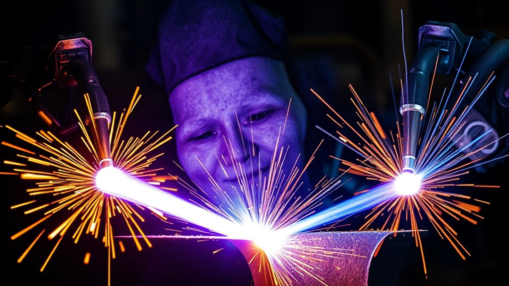
Plasma Arc Temperature vs. Other Heat Sources
You’ll benchmark plasma arc temperatures near 40,000°F (22,000°C) against oxy-fuel flames at ~5,600°F (3,100°C) to quantify the cut energy advantage per industry data.
You’ll also compare plasma to lightning at ~30,000°F (16,600°C) to frame transient natural extremes versus sustained process heat.
Finally, you’ll contrast plasma with the sun’s ~10,000°F (5,500°C) surface to underscore that industrial plasma exceeds common astrophysical reference points.
Plasma vs. Oxy-Fuel
Although both processes cut metal thermally, plasma’s arc temperature—reaching up to 40,000°F (22,000°C)—dwarfs an oxy‑fuel flame’s ~5,600°F (3,100°C), driving fundamentally different performance.
You’ll see higher plasma efficiency on thin to medium conductive metals due to greater energy density, faster kerf propagation, and minimal heat-affected zones.
Oxy fuel limitations stem from the lower flame temperature and reliance on oxidation, which reduces speed and finish quality on stainless, aluminum, and other nonferrous conductors.
Plasma delivers cleaner edges, less dross, and tighter tolerances, supporting intricate profiles and reduced post‑processing.
For very thick ferrous plate, oxy-fuel can remain cost‑effective due to simple equipment and preheat-assisted piercing, but it sacrifices precision.
Choose plasma when you need speed, accuracy, and conductive‑metal capability; choose oxy-fuel for heavy ferrous sections at lower equipment cost.
Plasma vs. Lightning
Curious where a plasma arc stacks up against nature’s fiercest heat sources? You’ll see that a modern plasma cutter’s arc reaches about 40,000°F (22,000°C), exceeding typical lightning characteristics, which peak near 30,000°F (16,600°C).
While lightning delivers immense, transient energy with microsecond duration and irregular current paths, a plasma torch provides a sustained, constrained arc with controlled amperage, gas flow, and nozzle geometry.
That control matters. You can channel energy density precisely into conductive metals, achieving rapid melting and clean kerf quality—key for repeatable, standards-compliant plasma applications.
Unlike lightning’s stochastic strike pattern and variable impedance, a cutter’s arc length, stand-off, and duty cycle are engineered for consistent thermal input, predictable heat-affected zones, and process reliability.
Net result: higher peak temperature and superior process control for productive cutting.
Plasma vs. Sun Surface
While the sun’s photosphere averages about 10,000°F (5,500°C), a plasma cutter’s arc routinely reaches roughly 40,000°F (22,000°C), delivering a localized heat source that far exceeds the solar surface in temperature.
In a strict solar comparison, you’re leveraging arc temperatures that are about 4x the photosphere, yet still far below the sun’s core (~27,000,000°F / 15,000,000°C). That distinction matters when you assess plasma properties, heat transfer, and process capability.
Because the arc is confined and electrically sustained, you achieve rapid melting, narrow kerfs, and minimal heat-affected zones relative to oxyacetylene (~5,432°F / 3,000°C).
The plasma arc’s temperature class aligns more closely with lightning (~54,032°F / 30,000°C), underscoring its intensity. For specification-driven cutting, these quantified deltas translate into predictable penetration, faster travel speeds, and repeatable cut quality.
Factors That Influence Arc Temperature
Because arc temperature dictates cut quality and speed, you need to control the variables that drive it: gas type and purity (thermal conductivity, specific heat, ionization potential), gas flow/pressure, output current (amperage), and the workpiece’s thickness and composition.
In plasma technology, these parameters form your heat management toolkit, determining whether the arc approaches its upper bound near 40,000°F (22,000°C).
Select high-purity process gas to stabilize ionization and maintain consistent thermal conductivity. Increase gas flow and pressure to intensify the plasma jet’s momentum and constriction; higher pressure generally yields a hotter, denser arc, but monitor nozzle wear and arc blow-off.
Set amperage to match material and kerf target—higher current raises energy density and arc temperature, improving penetration but elevating dross risk.
Scale temperature to section thickness: thicker plate absorbs heat and resists melting, requiring hotter arcs and tighter standoff control.
Finally, adjust for alloy composition—high-conductivity metals (e.g., aluminum, copper) demand higher thermal input than carbon steel.
Gas Choices and Their Temperature Effects
With arc temperature as your control variable, gas selection becomes a primary spec: different gases set different thermal ceilings via ionization potential and thermal conductivity.
Arc temperature drives gas choice—ionization and conductivity set your thermal ceiling and cutting performance.
You should treat gas selection as a design input that drives temperature variation, arc chemistry, and cut quality. Compressed air is the baseline: expect about 20,000°F (11,000°C), suitable for mild steel with acceptable edge oxidation.
Nitrogen delivers similar arc temperatures but improves stainless and aluminum edges by minimizing oxidation and stabilizing the plasma column.
For maximum heat density, specify argon–hydrogen blends. The hydrogen fraction elevates enthalpy and thermal conductivity, pushing arc temperatures toward the upper envelope of plasma systems, near 40,000°F (22,000°C), and yielding superior fusion and speed on thick stainless and nickel alloys.
Control flow rate as a secondary thermal lever: higher, well-regulated flow increases arc constriction and stability, raising effective temperature and cutting efficiency.
Match gas chemistry to material and desired edge quality to minimize heat-affected zone and rework.
Amperage, Air Pressure, and Arc Intensity
You’ll set current to control arc intensity, with higher amperage generating hotter plasma that can exceed 40,000°F (22,000°C) and cut thicker sections while maintaining kerf quality.
You’ll regulate air pressure to stabilize the arc and increase energy density, improving edge quality and efficiency versus under-pressured, wandering arcs.
You’ll manage arc density via gas flow and composition, targeting typical arc temperatures near 28,000°C (50,000°F) and selecting gases (e.g., nitrogen) to optimize cut quality on stainless steel and aluminum.
Current Setting Impact
Although many factors influence plasma temperature, amperage is the primary driver: increasing current raises arc energy density and temperature, routinely pushing the plasma column beyond ~40,000°F (22,000°C) for efficient cutting.
Your current adjustment defines power input (I × V) and constrains heat flux at the kerf. Leverage amperage influence to match material thickness: thin sheet demands lower current to minimize heat-affected width; thicker plate requires higher amperage to maintain full-penetration temperature and cut speed.
Set current according to the torch’s rated duty cycle and consumable spec to prevent nozzle erosion and arc instability. Verify arc quality by monitoring cut face, dross, and kerf angle.
When optimizing, change one parameter at a time, document results, and lock in validated current setpoints.
Air Pressure Influence
Because plasma is both an electrical and fluid-dynamic system, air pressure directly shapes arc intensity and temperature by governing gas density, jet velocity, and constriction at the nozzle.
You’ll see the hottest, most stable arc when air pressure is set in the typical 60–75 psi window, where ionization is efficient and arc efficiency is maximized. Within this range, higher pressure narrows the jet, increasing energy density and temperature. Pair it with higher amperage and you elevate arc power, enabling cleaner penetration on thicker sections.
Avoid over-pressurizing. Excessive flow cools and dilutes the column, lowering temperature and cutting performance. Under-pressurizing broadens the jet, reduces constriction, and wastes power.
Verify delivered pressure at the torch while flowing, and tune to the manufacturer’s spec to balance amperage, air pressure, and arc efficiency.
Arc Density Control
Set air pressure in the 60–75 psi window and pair it with the correct amperage to control arc density, intensity, and temperature. Higher amperage concentrates the plasma column, raising arc intensity and pushing localized temperatures toward the 40,000°F (22,000°C) regime.
Increasing air pressure improves gas ionization, boosting arc stability and arc density; however, excessive pressure can blow out the arc and degrade cutting quality.
Match parameters to material thickness. For thin sheet, run lower amperage and moderate pressure to minimize kerf width, heat-affected zone, and dross.
For thicker plate, increase amperage and hold pressure near the upper range to sustain energy density and maintain travel speed.
Continuously verify cut face angularity, kerf uniformity, and slag formation, then fine-tune amperage/pressure to prevent overheating while maximizing cutting quality.
Nozzle Design, Standoff, and Torch Angle
Three controllable factors—nozzle design, standoff, and torch angle—govern how hot the plasma arc gets at the cut zone and how consistently that heat is delivered.
You increase nozzle efficiency by selecting a smaller orifice that constricts the jet, raising energy density and arc core temperature. Match orifice size to current and gas flow to maintain torch stability; oversizing reduces temperature, undersizing risks double-arcing and tip damage.
Set standoff to the manufacturer’s specified range to keep the arc column focused. Too close and you erode the nozzle and destabilize the arc; too far and the arc stretches, cools, and widens, lowering heat flux. Use height control to hold ±0.25 mm where applicable.
Keep the torch perpendicular to maximize energy transfer. A tilt introduces asymmetric heat distribution, increases kerf taper, and can drop localized temperature at the intended interface.
Lock angle tolerances within 1–2 degrees to maintain consistent arc heating and predictable cut geometry.
Material Thickness and Cutting Speed Impacts
Although plasma jets can exceed 40,000°F (22,000°C), material thickness and travel speed ultimately govern how that heat translates into cut quality. You’ll see a predictable inverse relationship: as material thickness increases, cutting speed must decrease to maintain full penetration, straight kerfs, and minimal dross.
Thicker sections demand higher amperage sources that generate hotter, denser arcs capable of deeper energy coupling; otherwise, the jet stalls and leaves taper or uncut webs.
Set cutting speed to balance energy input with ejection of molten metal. Too fast on thick plate causes top-edge rounding, lag lines, and incomplete severance. Too slow overheats the kerf, widens HAZ, and increases dross.
High-amperage systems expand the workable thickness window by sustaining a hotter arc at an appropriate travel rate.
Use spec-based process windows: match amperage to material thickness, then tune cutting speed to keep the arc column centered, sparks exiting 10–15° from vertical, and the kerf uniformly bright without secondary flaming.
Adjusting Settings to Modify Arc Temperature
While plate thickness dictates the minimum heat you need, you can deliberately raise or focus arc temperature by tuning core process variables: amperage, gas, nozzle, and torch geometry.
Increase current first; amperage is the primary driver of plasma enthalpy, so higher settings elevate arc temperature and sustain penetration on thicker stock. Perform temperature calibration after each change to validate cut quality, kerf width, and dross levels.
Optimize gas: adjust flow rate to maintain a stable, constricted column, and select composition by alloy—air for carbon steel, nitrogen or H35 mixes for higher thermal intensity and cleaner edges on stainless and aluminum.
Use smaller, high-constriction nozzles when you need a hotter, denser arc; verify nozzle condition to prevent turbulence.
Control torch geometry: keep standoff within the manufacturer’s spec and hold a consistent, slight lead angle to concentrate heat at the cut front.
Iterate arc adjustments systematically, logging parameters and results to converge on target thermal intensity.
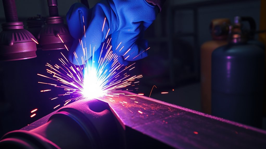
Safety Measures for Extreme Heat and Brightness
Two hazards dominate plasma cutting: extreme heat—arc cores can reach about 40,000°F (22,000°C)—and intense UV/IR radiation.
You mitigate both with protective equipment specified by welding standards. Wear a properly rated helmet with shade 8–12 lenses (per task and current), UV/IR-filtering safety glasses underneath, flame-resistant clothing (e.g., ASTM F1506 or NFPA 2112 rated), leather gloves, and boots.
Use heat resistant materials for screens, blankets, and table surfaces to contain spatter and molten slag.
Use heat-resistant screens, blankets, and tables to contain spatter and molten slag.
Control ignition sources: clear combustibles within the spark radius, shield drains and gaps, and keep an ABC fire extinguisher accessible.
Maintain local exhaust ventilation or fume extraction at the arc to keep exposure below permissible limits; supplement with a respirator when required.
Manage thermal load: adhere to the cutter’s duty cycle, monitor over-temperature indicators, and allow cooling intervals.
Verify secure workpiece grounding and dry, intact leads.
Establish a controlled arc zone with barriers and signage to protect bystanders’ eyes and skin.
Real-World Applications by Temperature Range
You’ll match temperature and amperage to application: thin-gauge sheet work uses lower arc energy to limit HAZ and warping, while still exceeding melting points for steel, aluminum, and stainless.
Medium plate fabrication leverages higher currents and optimized gas flow to maintain kerf quality and ISO 9013 cut-class tolerances.
Thick-section plate cutting demands peak thermal output—orders of magnitude hotter than ~5,600°F oxy-fuel—to achieve full penetration and acceptable taper at production speeds.
Thin-Gauge Sheet Work
Cut thin-gauge sheet with confidence by leveraging a plasma arc that reaches ~40,000°F (≈22,000°C) and a high-velocity gas stream to melt and eject metal, minimizing the heat-affected zone (HAZ).
You’ll achieve thin metal precision and clean cuts on 16 ga to 1/4 in sheet with reduced rework, as the dross load is typically negligible at proper amperage, standoff, and travel speed.
Apply amperage at the low end for the thickness, maintain a consistent arc length, and use fine-cut consumables to preserve edge quality and tight tolerances.
The extreme arc temperature enables rapid kerf formation and stable arc constriction, supporting intricate geometries common in HVAC ducting and automotive brackets.
Expect faster cycle times than mechanical shearing, with dimensionally accurate profiles and minimal thermal distortion when parameters are tuned per material and gauge.
Medium Plate Fabrication
For medium plate fabrication in the 1–2 in range, leverage plasma arc temperatures up to 40,000°F (≈22,000°C) to achieve high cut rates with controlled HAZ and tight dimensional tolerance.
You’ll realize medium plate advantages by pairing proper amperage with optimized gas flow to maintain arc stability and energy density for precision cutting.
On mild steel, compressed air improves kerf quality and reduces dross at these temperatures. For stainless and aluminum, switch to nitrogen; it sustains >20,000°F (≈11,000°C) in the jet, limiting oxidation and producing clean edges.
Calibrate current to plate thickness and travel speed to balance kerf width, angularity, and HAZ per shop QA metrics.
Validate results with cut-face roughness (Ra), bevel angle, and dross classification to guarantee repeatable, code-compliant fabrication.
Thick-Section Plate Cutting
Thick-section plate cutting leverages plasma arc temperatures approaching 40,000°F (≈22,000°C) to drive fast penetration and stable kerf formation on >2 in materials while holding a narrow HAZ for structural integrity. You’ll run higher amperage to boost arc energy density, improving cutting efficiency and edge quality versus oxy-fuel on steel, aluminum, and stainless. The process remains cost-effective at scale due to faster travel speeds, reduced preheat, and minimal post-processing.
| Parameter | Guidance |
|---|---|
| Thickness (>2 in) | Select higher-amperage systems; verify duty cycle compliance |
| Material selection | Match gas blend to alloy; guarantee conductivity supports arc constriction |
| HAZ control | Optimize standoff, speed, and swirl gas to limit distortion |
| Quality metrics | Monitor kerf width, dross rate, and angularity per ISO 9013 |
Maintain proper consumable condition, precise gas flow, and CNC lead-ins to guarantee consistent penetration and cut geometry.
Frequently Asked Questions
Can Plasma Cutter Heat Warp Nearby Components or Finished Parts?
Yes. You can induce heat distortion in nearby components, especially with high duty cycles and thin-gauge alloys. Control material sensitivity by using standoff distance, water tables, heat sinks, optimized travel speed, intermittent sequencing, and adherence to AWS/ISO cut-quality tolerances.
Do Plasma Cutters Affect Shop Ventilation or Air Quality Requirements?
Yes. You must upgrade ventilation systems and air filtration to control metal fumes, ozone, and particulates. Follow OSHA/ACGIH limits, calculate capture velocity, use local exhaust hoods, HEPA/activated carbon filters, monitor airflow, and document maintenance to maintain compliant air quality.
What Eye Protection Shade Number Is Recommended for Plasma Cutting?
Worried it’ll be too dark? You’ll adapt quickly. For plasma cutting, you need eye protection with shade numbers 5–8 under 60 A, 8–10 for 60–200 A, and 10–12 above 200 A, per ANSI/ISEA Z87.1 guidance.
Can the Arc’s UV Radiation Damage Skin Like Sunburn?
Yes. The arc’s UV exposure can cause erythema akin to sunburn. You should use skin protection: flame-resistant long sleeves, gloves, neck coverage, and ANSI Z87.1 face shields. Cover exposed skin; limit duration; follow OSHA/NIOSH guidelines for radiant energy.
How Does Duty Cycle Limit Continuous High-Temperature Cutting?
Duty cycle defines allowable arc-on time per 10 minutes; exceed it and you trigger thermal limits. You monitor duty cycle to mitigate overheating risks, maintain insulation class ratings, protect IGBTs/torch consumables, and guarantee compliance with manufacturer specifications and IEC/EN standards.
Conclusion
You chase a “hot knife through butter,” yet the arc you hold can hit 50,000°F (≈28,000°C)—orders of magnitude beyond an oxy-fuel flame’s 5,600°F. You fine-tune amperage, gas mix, and standoff like you’re aligning to ISO-grade tolerances, all to keep a microscopic column of star-hot plasma stable. Ironically, that sun-in-your-hand trims heat-affected zones to millimeters. Respect it: verify airflow, duty cycle, PPE shade, and interlocks. Then let physics do the clean, surgical cutting you specified.