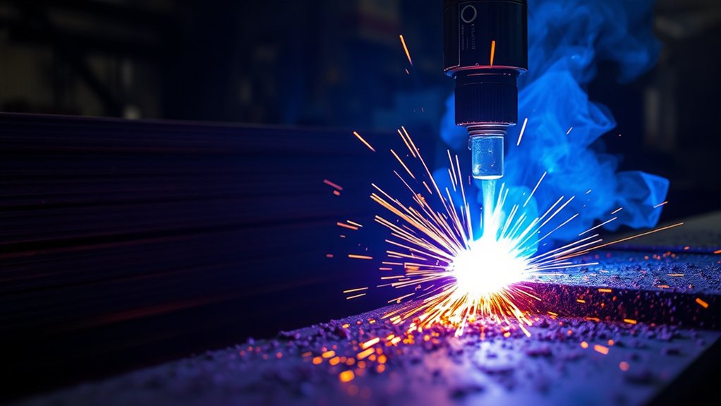
A plasma cutter produces one of the hottest controlled arcs used in a fabrication shop. The plasma arc can approach 40,000°F (about 22,000°C), but that number describes the hottest part of the ionized gas—not the temperature of the entire torch, workpiece, or cutting table. Cut quality depends more on using the correct cut chart than on chasing a maximum temperature.
The practical controls are amperage, arc voltage or torch height, gas type and flow, travel speed, consumable condition, and material thickness. When those settings match the machine and metal, the arc melts a narrow path and the high-speed gas jet removes the molten metal.
Quick Answer
A plasma cutter arc can approach 40,000°F (about 22,000°C). That is the temperature of the hottest plasma stream, not the whole machine or workpiece. Amperage, gas, pressure or flow, torch height, speed, and consumable condition control how much useful heat reaches the cut.
Key Takeaways
- Plasma arcs can approach 40,000°F, roughly four times the Sun’s visible-surface temperature.
- Arc temperature and heat input are not the same: current, voltage, speed, and arc constriction affect cutting power and energy delivered to the metal.
- Use the manufacturer’s cut chart for amperage, gas, pressure or flow, consumables, pierce height, cut height, and speed.
- Clean, dry gas and undamaged consumables usually improve cut quality more than random pressure or current changes.
- Eye protection, flame-resistant clothing, ventilation, electrical precautions, and hot-work controls are essential.
At a Glance
| Time Required | About 5–15 minutes to verify the cut chart, inspect consumables, and make a test cut |
| Difficulty | Beginner to intermediate; mechanized multi-gas systems require trained operators |
| Tools Needed | Machine manual and cut chart, correct consumables, clean dry gas, PPE, and scrap matching the job material |
| Cost | Usually no added setup cost; filters, gas, electrodes, nozzles, shields, or cartridges are replaced as needed |
What’s in This Article
- Maximum Plasma Cutter Arc Temperature
- Plasma Arc Temperature vs. Other Heat Sources
- Factors That Influence Arc Temperature
- Gas Choices and Their Temperature Effects
- Amperage, Air Pressure, and Arc Intensity
- Nozzle Design, Standoff, and Torch Angle
- Material Thickness and Cutting Speed Impacts
- How to Tune a Plasma Cutter for Better Heat Transfer
- Safety Measures for Heat, Light, Fumes, and Electricity
- Applications by Arc Energy and Cut Capacity
- Frequently Asked Questions
- Sources
Maximum Plasma Cutter Arc Temperature
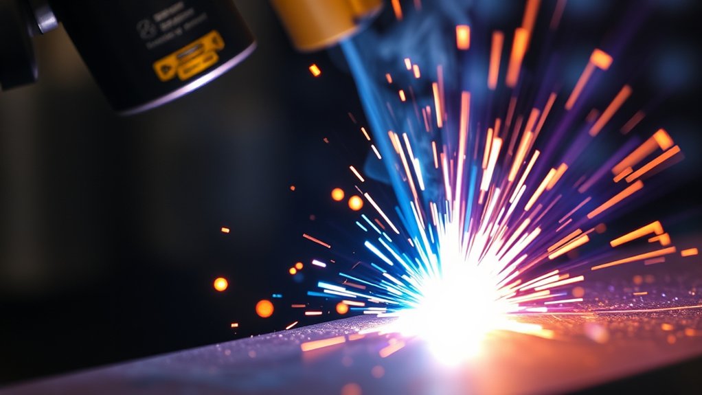
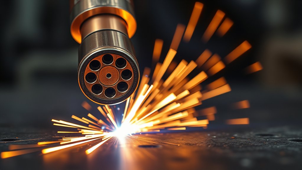
According to Hypertherm’s explanation of plasma cutting, a plasma cutting arc can approach 40,000°F (about 22,000°C). Gas is forced through a narrow nozzle and energized until it becomes an electrically conductive plasma. The arc melts the workpiece, and the gas jet blows the molten metal out of the kerf.
The temperature is not uniform across the plasma column. The hottest core is surrounded by cooler regions, and the workpiece does not become 40,000°F throughout. Steel, stainless steel, aluminum, copper, and other conductive metals melt at far lower temperatures; the arc only needs to deliver enough energy quickly enough to melt and eject a narrow path.
A plasma cutter may produce a 40,000°F arc, but good cutting comes from controlled energy transfer—not from trying to maximize temperature.
Arc Temperature vs. Heat Input
Temperature describes how energetic the plasma particles are. Heat input describes how much energy reaches the workpiece over time and distance. In practical cutting, heat input changes with output current, arc voltage, travel speed, gas flow, torch height, and arc efficiency.
Increasing amperage usually increases available cutting power and thickness capacity, but it does not give the operator a simple, linear “temperature dial.” A worn nozzle, incorrect torch height, contaminated air, or poor speed can waste that extra power and produce a worse edge.
Note: Normal shop thermometers and infrared guns cannot accurately measure the core of a plasma arc. Operators judge the process through the machine’s cut chart, arc behavior, kerf shape, dross, bevel, and cut-face lines.
Plasma Arc Temperature vs. Other Heat Sources
Temperature comparisons show how intense the arc is, but they do not predict cutting performance by themselves. Duration, energy density, gas chemistry, arc size, and control matter just as much.
| Heat source | Approximate temperature | What the number means |
|---|---|---|
| Plasma cutting arc | Approaching 40,000°F (22,000°C) | A sustained, constricted arc used to melt and eject conductive metal |
| Oxy-acetylene flame | Around 5,700–6,000°F (about 3,150–3,300°C) | Fuel-dependent flame; oxy-fuel cutting also relies on rapid oxidation of carbon steel |
| Lightning-heated air | Around 50,000°F (about 28,000°C) | A brief, uncontrolled heating of air around the lightning channel |
| Sun’s photosphere | About 10,000°F (5,500°C) | The visible “surface”; the Sun’s core and corona are much hotter |
Plasma vs. Oxy-Fuel
An oxy-acetylene flame is commonly around 6,000°F, according to ESAB’s oxy-fuel comparison. Standard oxy-fuel cutting heats carbon steel to its ignition temperature, then uses a high-purity oxygen jet to drive an exothermic oxidation reaction and remove slag.
Plasma is hotter and works on electrically conductive metals, including mild steel, stainless steel, aluminum, copper, and brass. It is often faster and more precise on thin and medium material. Oxy-fuel remains practical for very thick carbon steel, especially where equipment cost and portability matter more than a narrow kerf.
Plasma vs. Lightning
A plasma cutter’s arc is slightly cooler than the air heated by a typical lightning channel. The National Weather Service says lightning can heat air to about 50,000°F. The useful difference is control: lightning lasts briefly and follows an uncontrolled path, while a torch sustains and constricts an arc at a set current, height, and speed.
Plasma vs. Sun Surface
The Sun’s photosphere is about 10,000°F, so a plasma arc can be roughly four times hotter than the visible surface. That comparison is limited: the Sun covers an enormous area, and its core and corona are far hotter than a cutting arc.
Factors That Influence Arc Temperature
You do not normally set plasma temperature directly. Instead, you set or verify the variables that shape the arc and control energy transfer:
- Output current: Sets the available cutting power and must match the consumable set and material thickness.
- Arc voltage and torch height: A longer arc generally has higher voltage but loses focus; a short, correct arc transfers energy more efficiently.
- Gas type, purity, flow, and pressure: These affect ionization, arc constriction, oxidation, molten-metal removal, and consumable cooling.
- Nozzle and electrode condition: Eroded orifices and electrode pits can distort the arc.
- Travel speed: Speed controls how long heat acts on each part of the kerf.
- Material and thickness: Alloy chemistry, thermal conductivity, surface condition, and thickness change the required process.
- Power supply duty cycle: The machine must stay within its rated on-time at the stated current and ambient temperature.
High-conductivity metals such as aluminum and copper carry heat away from the cut quickly. They may need a different gas, current, speed, or consumable than carbon steel of the same thickness. Coatings, rust, paint, and mill scale can also change arc starting and fume hazards.
Pro Tip: Before changing current or gas pressure, install the correct consumables, inspect the nozzle orifice, drain the compressor, verify filters, and make sure the work lead has clean metal-to-metal contact.
Gas Choices and Their Temperature Effects
Gas choice affects more than peak temperature. It also changes arc stability, cut speed, oxidation, edge chemistry, dross, consumable life, and the ability of the jet to remove molten metal. The correct choice depends on the machine, torch, material, thickness, and desired finish.
Hypertherm’s plasma gas guide identifies these common uses:
| Plasma gas | Typical use | Important limits |
|---|---|---|
| Clean, dry air | Economical general cutting of mild steel, stainless steel, and aluminum on compatible air-plasma systems | Can oxidize or nitride the cut face; moisture and oil shorten consumable life |
| Oxygen | High-quality, fast cutting of mild steel on approved systems | Not a general choice for stainless steel or aluminum; requires the specified torch, consumables, and ventilation |
| Nitrogen | Stainless steel and aluminum, especially on multi-gas systems | Shield gas and cut chart must match the system |
| Argon-hydrogen | Thicker stainless steel and aluminum on equipment designed for H-35 or another approved blend | Hydrogen blends are flammable and must never be improvised or used on an unapproved torch |
Do not substitute gases because they appear to run “hotter.” Gas passages, regulators, seals, torch cooling, consumables, ignition sequences, and safety controls are system-specific.
Amperage, Air Pressure, and Arc Intensity
Amperage and gas delivery work together, but more is not automatically better. The correct settings come from the cut chart for the installed consumables.
Current Setting Impact
Current determines how much electrical power the arc can deliver. Thin sheet usually needs a lower-current consumable and fast travel to limit kerf width and distortion. Thick plate needs more current and a system with enough recommended cut capacity and duty cycle.
Running a nozzle far above its rated amperage accelerates erosion and can cause double-arcing, poor angularity, or torch damage. Running far below a consumable’s intended range can also produce an unstable arc. Use the current range specified for that exact nozzle, electrode, shield, or cartridge.
Air Pressure Influence
There is no universal plasma-cutter pressure such as 60–75 psi. Some machines regulate pressure automatically; others require the operator to set inlet or flowing pressure. Hose length, fittings, filters, compressor recovery, and duty cycle can all affect pressure at the torch.
Check pressure while gas is flowing when the manual requires it. Low flow may fail to eject molten metal or cool consumables. Excessive pressure or flow can destabilize the arc, cause starting trouble, or move the process outside the tested cut chart.
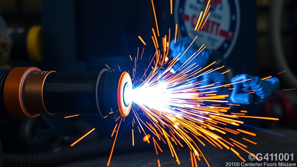
Arc Density Control
Arc density comes from the relationship among current, nozzle orifice, gas swirl, gas flow, and arc length. A healthy, correctly sized nozzle constricts the plasma column. Torch height control then keeps the arc length stable as the plate moves or warps.
Do not drill, file, or reshape a nozzle to “focus” the arc. Use only the consumable set approved for the torch and current level.
Nozzle Design, Standoff, and Torch Angle
Nozzle design, standoff, and torch angle determine where the arc’s energy lands. A nozzle with the correct orifice and gas swirl keeps the arc centered. A worn or nicked orifice can deflect it and create unequal bevel.
Standoff is the distance from the torch tip or shield to the workpiece during cutting. Some handheld consumables are designed for drag cutting; others require a gap. Mechanized systems often use a higher pierce height, then lower to a separate cut height. Never assume one distance works for every consumable.
Too much standoff lengthens and weakens the arc, widens the kerf, and increases bevel. Too little can allow molten spatter to reach the nozzle, cause double-arcing, or shorten consumable life. Hold the torch near 90 degrees for ordinary square cuts unless the procedure calls for a bevel.
Pro Tip: If one side of a cut is consistently more beveled than the other, check torch squareness and nozzle wear before changing pressure or speed.
Material Thickness and Cutting Speed Impacts
Material thickness and travel speed determine how long the arc acts on the cut front. A speed that is too fast can leave an incomplete cut, heavy high-speed dross, excessive lag lines, or top-edge rounding. A speed that is too slow widens the kerf, increases low-speed dross, and puts more heat into the plate.
Use the manufacturer’s speed as the starting point. Spark direction is only a secondary check and varies by gas. Hypertherm notes that air-plasma arcs should leave the bottom of the cut close to vertical, nitrogen or argon-hydrogen may trail slightly, and oxygen may lead slightly. Always observe through the correct filter lens.
Recommended, Rated, and Severance Capacity
Plasma cutter thickness claims do not all mean the same thing:
- Recommended or production cut capacity is the thickness range intended for repeatable speed and quality.
- Rated cut capacity may describe a slower cut that still meets the manufacturer’s stated quality test.
- Severance capacity is the maximum thickness the machine can separate under favorable conditions, usually with slower speed and rougher edges.
For frequent work, size the machine around its recommended capacity rather than its maximum severance number.
How to Tune a Plasma Cutter for Better Heat Transfer
The goal is not to make the arc as hot as possible. The goal is to transfer enough energy to the cut while limiting dross, bevel, consumable wear, and distortion.
- Identify the exact material and thickness. Separate mild steel, stainless steel, and aluminum procedures.
- Open the manufacturer’s cut chart. Select the correct process, current, consumables, gas, inlet or cut-flow setting, pierce height, cut height, and speed.
- Inspect the gas supply. Drain water, verify filters, check for leaks or restrictions, and confirm adequate compressor flow at the required duty cycle.
- Inspect and install consumables. Replace an eroded electrode, out-of-round nozzle, damaged shield, or cracked retaining cap.
- Attach the work lead correctly. Use clean, bare metal close enough to the work to provide reliable electrical contact. Do not confuse the work lead with the machine’s protective earth ground.
- Make a test cut on matching scrap. Keep the torch square and use the chart speed.
- Change one variable at a time. Compare dross, bevel, kerf width, top-edge shape, lag lines, and whether the arc fully exits the plate.
- Record the successful setup. Note material grade, thickness, current, consumables, gas, pressure or flow, speed, and torch height.
| Cut symptom | Likely checks |
|---|---|
| Arc will not start or transfer | Work-lead contact, gas pressure or flow, consumable installation, torch-to-work distance, input power, and safety interlocks |
| Incomplete cut | Travel too fast, current too low, plate beyond capacity, low gas flow, excessive standoff, or worn consumables |
| Heavy dross | Confirm whether it is high-speed or low-speed dross before changing speed; also inspect gas quality and consumables |
| Wide kerf or rounded top edge | Excessive standoff, slow travel, wrong consumable, excessive current, or worn nozzle |
| Unequal bevel | Torch not square, nozzle damage, wrong travel direction for the best side, or unstable height |
Safety Measures for Heat, Light, Fumes, and Electricity
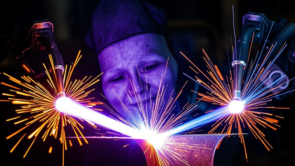
Plasma cutting exposes the operator and bystanders to intense visible, ultraviolet, and infrared radiation; flying molten metal; hot surfaces; noise; fumes; compressed gas; and potentially lethal electrical energy. Follow the machine manual, workplace hot-work procedure, and applicable regulations.
Warning: Never cut a sealed or pressurized container, or a drum, tank, or pipe that has held flammable or toxic material, unless it has been professionally cleaned, isolated, vented, tested, and released under an approved hot-work procedure.
Eye, Face, and Skin Protection
Wear safety glasses with side protection under a cutting shield or helmet, plus flame-resistant clothing, leather gloves, closed footwear, and hearing protection as required. Shield nearby workers with noncombustible screens.
OSHA’s minimum protective shades for plasma arc cutting when the arc is clearly visible are:
- Less than 300 A: shade 8 minimum
- 300–400 A: shade 9 minimum
- 400–800 A: shade 10 minimum
Start darker and move lighter only when you can see the cut without going below the required minimum or the machine manufacturer’s recommendation. An auto-darkening helmet must cover the required shade range and be rated for cutting.
Fume and Ventilation Controls
Plasma cutting melts metal and can generate airborne metal fume, ultrafine particles, ozone, nitrogen oxides, and contaminants from paint, plating, oil, or other coatings. Stainless steel fume may contain chromium and nickel; galvanized metal can produce zinc oxide; old coatings may contain lead or cadmium.
Use local exhaust ventilation that pulls contaminants away from the breathing zone. Remove coatings when it can be done safely, review the material’s safety data, and use respiratory protection only as part of a proper hazard assessment and respiratory-protection program. General room airflow alone may not control exposure, especially in enclosed spaces.
Electrical, Fire, and Explosion Safety
- Keep the body, gloves, clothing, floor, torch, and work area dry.
- Inspect the torch lead, work lead, power cord, plug, and enclosure before use.
- Disconnect input power before changing internal parts or servicing the machine; follow lockout/tagout rules where applicable.
- Remove or shield combustibles, control sparks that can pass through openings, and provide the extinguisher and fire watch required by the hot-work plan.
- Let cut parts and slag cool, or mark and handle them as hot metal.
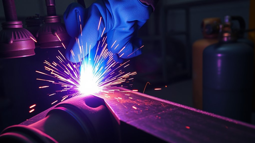
- Secure compressed-gas cylinders upright and protect them from slag, sparks, electrical contact, and physical damage.
OSHA’s welding and cutting requirements call for a fire-safe area, protection of combustibles, suitable eye protection, and cleaning and venting of used containers before hot work.
Warning: Aluminum cut over or under water can generate and trap hydrogen. Do not cut aluminum alloys on a water table unless the table and ventilation system are designed to prevent hydrogen accumulation and the manufacturer’s risk controls are in place. Never cut aluminum-lithium alloys in the presence of water.
Duty Cycle and Overheating
Duty cycle is the percentage of a stated test period—commonly 10 minutes—that the machine can cut at a specified current and ambient temperature before it needs cooling. A 60% duty cycle at the stated rating generally means up to six minutes of cutting followed by four minutes of cooling in that test period.
Duty cycle changes with output current, input voltage, ambient temperature, airflow, altitude, and manufacturer test conditions. Stop if an over-temperature indicator appears, keep cooling vents clear, and never bypass thermal protection.
Applications by Arc Energy and Cut Capacity
Operators do not normally select a numerical arc temperature for each job. They select a tested process window that provides the required current, gas, consumables, height, and speed.
Thin-Gauge Sheet Work
Thin sheet needs a small, controlled kerf and short heat exposure. Use the lower-current or fine-cut process approved for the thickness, maintain fast steady travel, and plan cut order so heat does not build in one area. A slatted table, heat sink, or manufacturer-approved water table can help control distortion where appropriate.
Typical applications include HVAC ducting, electrical panels, signs, brackets, and light automotive fabrication. The arc is still extremely hot, but the short dwell time limits the heat-affected zone.
Medium Plate Fabrication
Medium plate often falls within a plasma system’s most productive range. Correct current and speed can provide a narrow kerf, manageable bevel, and limited dross. Air is economical for general work, while multi-gas systems may use oxygen for mild steel or nitrogen-based processes for stainless steel and aluminum.
Common uses include structural brackets, machine frames, agricultural repairs, trailer parts, and fabrication components.
Thick-Section Plate Cutting
Thick plate needs higher available power, slower travel, adequate pierce capacity, and close control of torch height. Edge quality may decline as the job approaches rated or severance capacity. Piercing thick plate can also throw more molten material toward the torch, so the specified pierce height and delay are important.
| Parameter | Guidance |
|---|---|
| Thickness | Select a system with enough recommended capacity, pierce rating, and duty cycle for routine work |
| Material selection | Match the gas process and consumable set to the alloy and thickness |
| Heat control | Use the specified cut height, speed, lead-in, and cut sequence to limit distortion |
| Quality checks | Inspect kerf width, dross, bevel angle, cut-face lines, top-edge shape, and full penetration |
Frequently Asked Questions
Can plasma cutter heat warp nearby components or finished parts?
Yes. Thin sheet, long cuts, closely spaced profiles, and heat-sensitive alloys can distort. Use the correct speed, lower-current process when approved, balanced cut sequencing, adequate support, and a manufacturer-approved water table or heat sink where suitable. Remove nearby electronics, seals, hoses, and finishes from the heat and spark path.
Do plasma cutters affect shop ventilation or air-quality requirements?
Yes. The process can produce metal fume, ultrafine particles, ozone, nitrogen oxides, and coating byproducts. Use local exhaust near the arc and assess the specific metal, coating, cut duration, table design, and room. Stainless, galvanized, painted, plated, or unknown material may require added controls.
What eye-protection shade number is recommended for plasma cutting?
When the arc is clearly visible, OSHA lists shade 8 as the minimum below 300 A, shade 9 at 300–400 A, and shade 10 at 400–800 A. Follow the machine manual and workplace requirements, start with a darker shade, and wear side-protected safety glasses beneath the cutting shield.
Can the arc’s UV radiation damage skin like sunburn?
Yes. Plasma arcs emit ultraviolet and infrared radiation that can injure eyes and burn exposed skin. Cover the neck, arms, hands, and legs with flame-resistant clothing and gloves, and shield bystanders from direct and reflected arc light.
How does duty cycle limit continuous high-temperature cutting?
Duty cycle limits how long the power supply can cut at a stated current and test temperature before cooling is required. For example, a 60% rating in a 10-minute test period generally allows six minutes on and four minutes off at that rating. Lower current may increase duty cycle; hot, dusty, restricted, or high-altitude conditions may reduce cooling.
Can a plasma cutter cut any metal?
It can cut electrically conductive metals, including carbon steel, stainless steel, aluminum, copper, and brass, when the system has enough capacity and the correct process. It does not cut wood, glass, concrete, or other nonconductive materials by the normal transferred-arc method.
Can you measure a plasma cutter’s arc temperature with an infrared thermometer?
Not accurately. The arc is small, bright, moving, partly transparent, and far outside the range of ordinary infrared thermometers. Arc temperatures are measured with specialized optical and spectroscopic methods. Shop operators should use the cut chart and inspect the cut rather than trying to measure the arc core.
Sources
- Hypertherm: What Is a Plasma Cutter? — plasma formation, cutting method, and the arc temperature approaching 40,000°F
- Hypertherm: Guide to Plasma Gas Selection — air, oxygen, nitrogen, and argon-hydrogen process guidance
- Hypertherm Safety and Compliance Manual — electrical, fire, fume, compressed-gas, and aluminum water-table hazards
- OSHA 29 CFR 1910.133: Eye and Face Protection — minimum plasma arc cutting filter shades
- OSHA 29 CFR 1910.252: Welding, Cutting, and Brazing — fire prevention, used containers, PPE, and hot-work controls
- OSHA: Controlling Hazardous Fume and Gases During Welding — fume constituents, exposure factors, and ventilation guidance