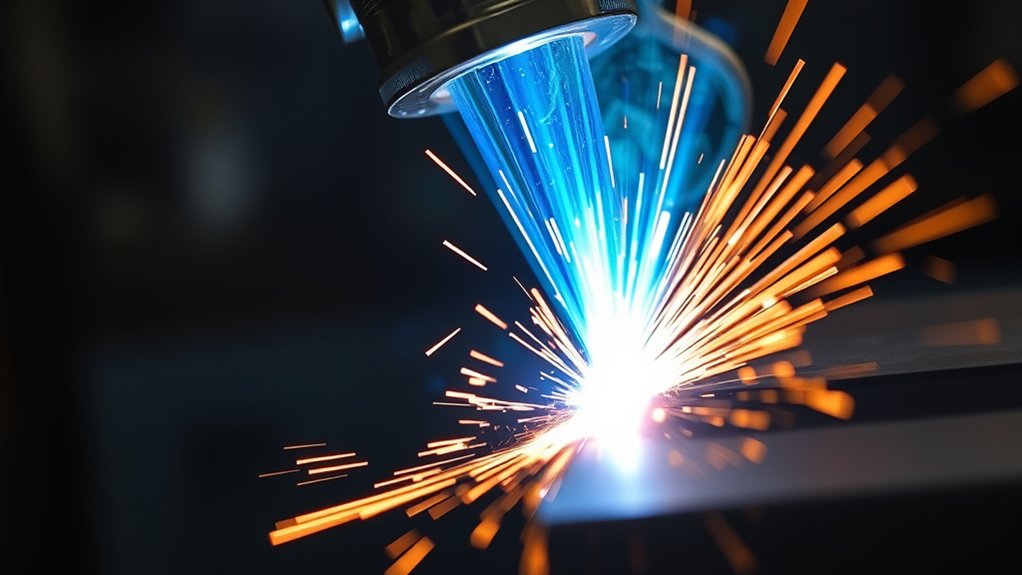
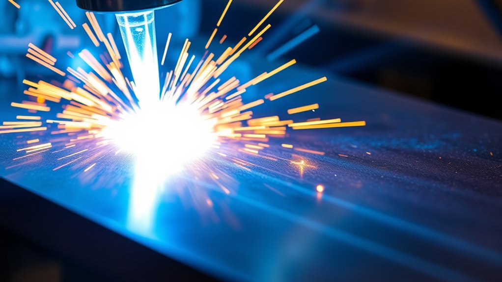
You’re working with an arc that can exceed 40,000°F (≈22,000°C), hot enough to instantly ionize gas and melt conductive metals with a tight heat-affected zone. That temperature isn’t fixed—it shifts with gas type, amperage, nozzle geometry, standoff, and material thickness. Compared to oxy-fuel or lasers, plasma’s thermal profile changes your cut speed, kerf, and distortion risk. Get those variables right, and precision follows—miss them, and your cut quality tells the story.
How Hot Can a Plasma Arc Get?
At full output, a plasma cutter’s arc can exceed 40,000°F (22,000°C), rivaling lightning and far surpassing an oxy-fuel flame (~5,600°F/3,093°C).
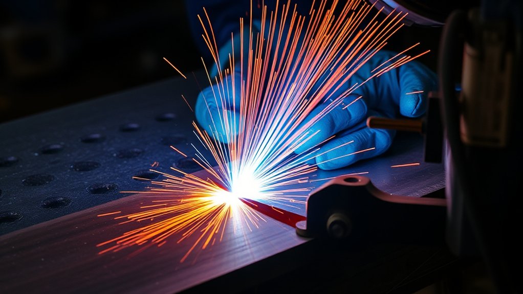
You’re working with a highly ionized gas column whose plasma arc properties include extreme enthalpy density, high electron temperature, and focused energy flux. That heat rapidly melts electrically conductive metals—steel, aluminum, copper—while the jet’s momentum ejects molten material to form a kerf.
You should interpret “how hot” as the arc core temperature, not base metal temperature. Peak values routinely surpass 22,000°C; reported maxima approach lightning-level temperatures.
Compared to combustion flames, the plasma’s energy is more concentrated, so localized melting is faster and HAZ width is narrower. Material thermal conductivity matters: high-conductivity alloys shed heat quickly, requiring sustained arc energy to maintain melt.
Although exact temperature depends on system configuration, the characteristic thermal profile remains: an intensely hot, constricted column delivering precise, high-rate melting of conductive workpieces consistent with industry cutting performance benchmarks.
Factors That Influence Plasma Arc Temperature
While the arc’s core can exceed 20,000 °C, its actual temperature depends on controllable parameters and workpiece conditions.
You can tune arc heat by managing plasma composition, gas flow, and electrical settings to match material and cut quality requirements. Temperature rises with higher energy density and effective heat transfer; it falls with inappropriate gas choice or poor setup.
Aim for stable constriction, proper standoff, and matched amperage to maintain a hot, focused jet with adequate thermal conductivity into the kerf.
1) Gas selection and plasma composition: Nitrogen, air, or argon‑hydrogen mixtures differ in ionization potential and thermal conductivity, shifting arc temperature, constriction, and energy delivery.
2) Amperage: Increasing current raises arc power density, elevating local temperature and cut speed, provided your nozzle and duty cycle support it.
3) Gas pressure/flow: Higher pressure improves constriction and momentum, intensifying the arc; excessive flow can destabilize it.
4) Material thickness: Thick sections demand hotter, higher‑energy arcs to maintain pierce and sustain molten ejection.
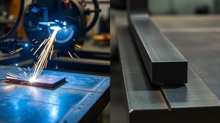
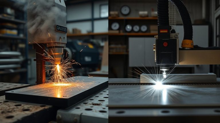
Comparing Plasma Cutting to Oxy-Fuel and Laser Heat
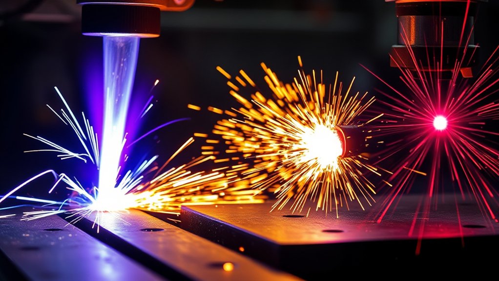
Having tuned arc heat through gas choice, current, and flow, you can benchmark plasma against oxy‑fuel and laser sources. Plasma arcs exceed 40,000°F, dwarfing oxy‑fuel’s ~5,600°F and surpassing lasers near 18,000°F. That thermal headroom drives plasma efficiency on conductive metals, especially under 1 inch, where velocity ejects molten material and stabilizes kerf quality. You’ll see faster pierce, higher travel speed, and robust edge integrity on mid‑thickness plate. Lasers win on cutting precision in thin-gauge work but at higher capital and operating cost. Oxy‑fuel lags in temperature and removal rate, limiting throughput and small-feature fidelity. For thicker sections, plasma maintains temperature and speed without degrading edges.
| Criterion | Practical takeaway |
|---|---|
| Heat level | Plasma >> Laser > Oxy‑fuel |
| Material domain | Conductive metals; thin to thick |
| Sub‑1″ throughput | Plasma fastest; clean kerf |
| Cutting precision | Laser best on thin stock |
| Cost/complexity | Plasma moderate; laser high; oxy‑fuel low |
Choose plasma when you need thermal capacity, speed, and balanced precision.
Gas Choices and Their Impact on Arc Heat
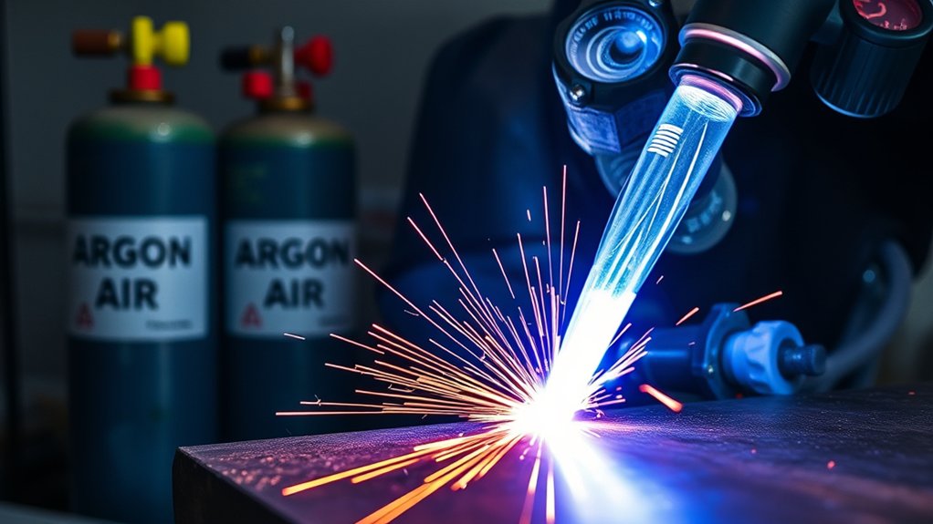
Because gas chemistry dictates ionization energy, thermal conductivity, and dissociation behavior, your plasma gas choice directly sets arc heat, stability, and cut quality.
Gas chemistry governs arc heat, stability, and cut quality—choose plasma gas to shape results.
You feel gas selection impact immediately: arc temperature, oxidation, kerf geometry, and edge finish shift with composition and flow. Use thermal properties comparison to match material and thickness with the correct plasma chemistry.
1) Air (compressed): About 20,000°F (11,000°C). Cost-effective for mild steel; higher oxygen content increases oxidation, widening kerf and dross tendency but maintains robust arc attachment.
2) Nitrogen: Similar peak temperatures with lower oxidation. Preferred for stainless and aluminum; cleaner edges and consistent cut speed due to favorable ionization potential and moderate thermal conductivity.
3) Argon‑hydrogen blends: For thick plate. Ar stabilizes; H2 elevates enthalpy and thermal conductivity, pushing arcs beyond 40,000°F (22,000°C) for narrow, smooth edges and high precision.
4) Flow rate effects: Higher flow lowers electron temperature yet raises electron density, improving column stability and momentum transfer, influencing arc intensity and cut uniformity without altering settings.
Machine Settings: Amperage, Nozzles, and Standoff
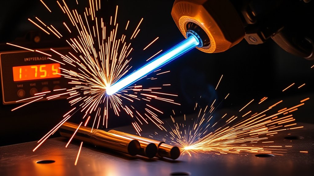
You set amperage to control heat output, recognizing that higher current drives arc temperatures that can exceed 20,000°C and increase kerf energy.
You pair the correct nozzle orifice with the material and thickness to concentrate the arc, then maintain the specified standoff to stabilize temperature and protect the consumables.
You verify these settings against the manufacturer’s cut charts to guarantee consistent cut quality and thermal input.
Amperage and Heat Output
Two machine settings define plasma heat delivery: amperage and how it’s focused at the tip. Set amperage settings to match material thickness and desired throughput. As amperage rises (typical 20–200 A), the arc energy density and heat distribution increase, pushing plasma temperatures well beyond 20,000 °C and boosting cut speed and kerf authority, with higher power draw.
- Target amperage: Use the lowest current that achieves full penetration and clean kerf; excess current wastes energy and widens HAZ.
- Cut quality: Higher amperage improves dross shedding and straightness, provided travel speed scales accordingly.
- Thermal budget: Balance amperage against duty cycle and input power to avoid thermal trips and consumable stress.
- Gas coordination: Pair current with gas flow; higher flow can lower electron temperature yet stabilize the arc and enhance efficiency.
Nozzle and Standoff Control
While amperage sets the arc’s thermal potential, nozzle geometry and standoff determine how that heat is delivered to the cut.
Use nozzle selection to control arc constriction: smaller orifices concentrate energy, sharpen the jet, and raise localized temperature for precision. Match nozzle size and current to material thickness; for example, a 200A nozzle supports cutting up to 50.8 mm while maintaining heat management and cut quality.
Execute standoff adjustment per manufacturer specs. Excessive standoff widens the kerf, drops heat density, and slows cutting.
Too little standoff overheats the nozzle, risks double-arcing, and damages consumables and edges. Dial in standoff to stabilize arc voltage, reduce dross, and improve edge squareness.
Verify settings with test cuts; adjust travel speed, gas flow, and torch height control to lock in performance.
Managing Heat Input for Precision and Speed
Although plasma cutting is fast and versatile, precision hinges on controlling heat input to limit distortion and preserve edge quality. To balance speed and accuracy, manage heat distribution and arc stability through parameter discipline and technique alignment.
1) Set travel speed by thickness. Increase speed to reduce dwell and the heat-affected zone on thin stock; slow slightly for thicker sections to maintain full penetration without overmelting edges.
2) Match amperage to material. Use lower amperage for thin metals to limit input energy; raise amperage for thicker plate to sustain a hotter arc that cleanly ejects molten material without excess kerf widening.
3) Control torch geometry. Hold a perpendicular torch angle for efficient energy coupling, and maintain the specified standoff to focus the arc column and prevent turbulence that destabilizes the cut.
4) Optimize gas flow. Adjust flow to the manufacturer’s spec to stabilize the plasma jet, cool the nozzle, and keep cut quality consistent across alloys, minimizing dross and taper while preserving dimensional tolerance.
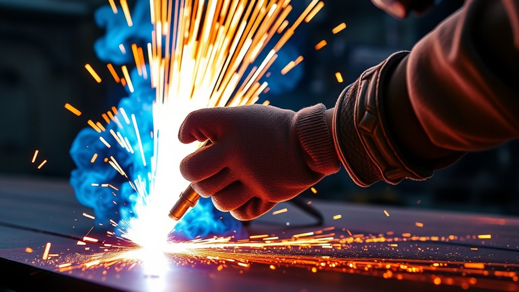
Safety Practices for Extreme Torch Temperatures
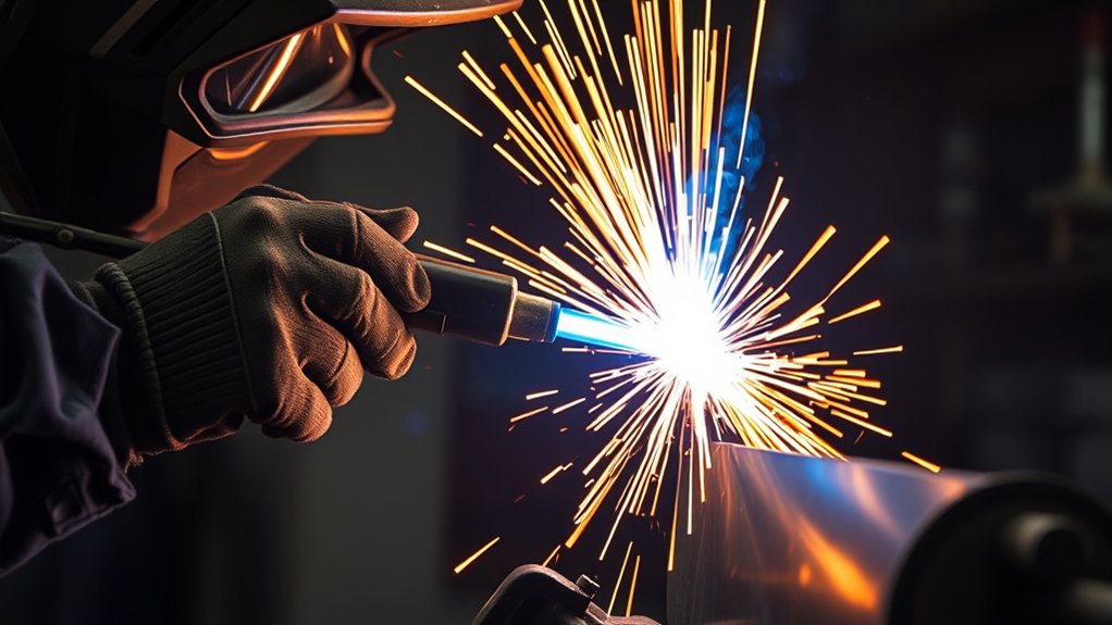
You’ll specify essential PPE and shields: flame-resistant garments, welding helmet with IR/UV-rated filter, insulated gloves, and heat-resistant barriers per ANSI Z87.1 and NFPA 2112.
You’ll guarantee ventilation meets OSHA/ACGIH limits, using local exhaust at the arc and verified airflow to control fumes and gases.
You’ll implement fire control: clear combustibles, maintain Class D/ABC extinguishers, establish hot-work permits, and stage emergency cooling stations for rapid burn response.
Essential PPE and Shields
Two layers of defense—PPE and engineered shields—stand between you and a plasma arc exceeding 20,000 °C.
Prioritize PPE selection that meets ANSI/ISEA Z87.1 and EN 166 for eye/face, and NFPA 2112 or ISO 11612 for garments. Choose shield types matched to task geometry and radiant load.
- Eye and face: Use an auto-darkening welding helmet with appropriate shade per ANSI Z87.1, plus a secondary face shield with IR/UV-rated visor to mitigate radiant heat and arc flash.
- Clothing: Wear flame-resistant jacket, pants, and hood; avoid synthetics. Use heat-resistant gloves meeting EN 407. Seal gaps at cuffs and collar.
- Foot protection: Safety boots with metatarsal guards, EH rating, and heat-resistant soles; spats for slag deflection.
- Barriers: Deploy heat-reflective curtains, spark containment screens, and insulating mats to block radiant exposure and spatter paths.
Ventilation and Fire Control
While the arc does the cutting, fumes, heat, and ejected sparks do the damage—so design the workspace for source-capture ventilation and strict fire controls.
Use local exhaust ventilation systems with hoods positioned at the plume to capture fumes and particulates at emission. Verify airflow meets manufacturer recommendations and maintain filters to prevent recirculation. Supplement with general dilution only if it won’t disrupt capture.
Control fire hazards by clearing combustibles and flammables at least 35 feet from the cutting zone.
Establish a designated, uncluttered area with noncombustible surfaces and spark containment. Stage compliant fire extinguishers within reach and confirm operator training.
Wear flame-resistant clothing and a face shield with appropriate filter rating. Conduct pre-job and post-cut hot-work inspections, monitor for smoldering, and document controls in your procedure.
Practical Tips for Temperature Control Across Materials
Because plasma arcs can exceed 20,000 °C, control heat input with standards-based adjustments: match amperage to material thickness, increase gas flow to dissipate heat without degrading kerf quality, and keep the torch perpendicular with correct standoff to concentrate energy and avoid undercut.
Plasma arcs exceed 20,000 °C—balance amperage, gas flow, and torch geometry to control heat and kerf quality.
Apply cutting techniques by material types: mild steel tolerates higher current; stainless and aluminum need tighter gas control to limit distortion and dross. Verify consumables; a worn nozzle destabilizes the arc, spikes temperature, and widens kerf.
1) Set amperage: 10–20 A per millimeter is a common baseline; step down on thin stock to minimize HAZ and warping.
2) Tune gas flow: raise flow to shed heat, but stop before jet divergence erodes edge quality; confirm with test cuts.
3) Maintain geometry: 90° torch angle, standoff per OEM spec; use height control for consistent arc length.
4) Control travel speed: on thin sections, increase speed; on thick plate, slow slightly for full penetration without overburn.
Frequently Asked Questions
How Does Ambient Humidity Affect Plasma Arc Stability?
Ambient humidity degrades plasma stability by increasing ionization thresholds and quenching arc columns. You’ll see misfires, wandering arcs, and dross. Mitigate humidity effects with dry air, desiccant dryers, proper dew point (<–40°C), compliant consumables, shield gas integrity, and grounded leads.
Can Arc Heat Damage CNC Electronics Nearby?
Yes—close arc proximity effects can roast sensitive CNC electronics like a miniature sun. You mitigate risk with electronic shielding techniques: grounded enclosures, IEC/UL-compliant cable routing, ferrites, optical isolation, robust bonding, EMI filters, separation distances, and forced-air cooling.
What Infrared PPE Is Recommended Beyond Standard Face Shields?
Use IR-rated infrared goggles (ANSI Z87.1+, IR 5+ shade) and thermal gloves meeting ASTM F1060/EN 407. Add aluminized face shield, flame-resistant hood (ASTM F1506), long sleeves, and neck protection. Ascertain coverage, compatibility with ventilation, and regular inspection.
How Does Duty Cycle Relate to Sustained Arc Temperature?
Of course, you want infinite heat forever. Instead, duty cycle limits sustained arc temperature: longer on-time raises conductor temperature, risks thermal saturation. You manage output current, cooling, and pause intervals per IEC/EN standards to keep arc temperature stable and components within ratings.
Are There Heat-Related Effects on Cut Edge Metallurgical Phases?
Yes. During plasma cutting, heat effects transform metallurgical phases at the cut edge: austenitization, martensitic quench, grain growth, tempering, and carbide dissolution/precipitation. You control outcomes via travel speed, current, stand‑off, assist gas, and post‑cut heat treatment.
Conclusion
You’ve seen that a plasma arc can exceed 40,000°F, and its temperature hinges on gas choice, amperage, nozzle, and standoff. Use these variables to tune cut quality, speed, and HAZ per AWS/ISO best practices. For example, switching from air to argon-hydrogen on 1-inch stainless at 200 A can boost edge smoothness and reduce dross, cutting rework by 30%. Always balance heat input with travel speed and duty cycle—and apply PPE and fume control without compromise.