A plasma cutter creates one of the hottest arcs used in a metal shop. The plasma jet can approach 40,000°F (about 22,000°C), but that number describes the hottest part of the arc—not the temperature of the entire plate. Clean cuts come from controlling amperage, gas, torch height, travel speed, and consumable condition rather than chasing a target temperature.
Quick Answer
A plasma cutter’s arc can approach 40,000°F (about 22,000°C). The workpiece does not reach that full arc-core temperature. You control usable heat with amperage, gas type and flow, nozzle condition, torch height, and travel speed, using the manufacturer’s cut chart as the starting point.
Key Takeaways
- The often-cited 40,000°F figure describes the plasma arc, not the average temperature of the metal.
- Amperage alone does not determine cut quality; speed, torch height, gas, and consumables work together.
- Use the exact cut chart for your machine, torch, consumables, material, and thickness.
- Clean, dry, oil-free gas helps protect consumables and keeps the arc stable.
- Eye protection, local exhaust, fire control, hearing protection, and electrical safety are essential.
At a Glance
| Time Required | About 5–15 minutes for setup and test cuts; longer for production tuning |
| Difficulty | Beginner to intermediate, depending on material and machine type |
| Tools Needed | Plasma cutter, correct consumables, suitable gas supply, work clamp, scrap metal, PPE, and ventilation |
| Cost | No added cost beyond gas, electricity, test material, and normal consumable wear |
What’s in This Article
- How Hot Can a Plasma Arc Get?
- Factors That Influence Plasma Arc Temperature
- Comparing Plasma Cutting to Oxy-Fuel and Laser Cutting
- Gas Choices and Their Impact on Arc Heat
- Machine Settings: Amperage, Nozzles, and Standoff
- Managing Heat Input for Precision and Speed
- Safety Practices for Plasma Cutting
- Practical Tips Across Materials
- Frequently Asked Questions
- Sources
How Hot Can a Plasma Arc Get?
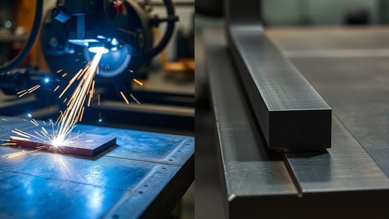
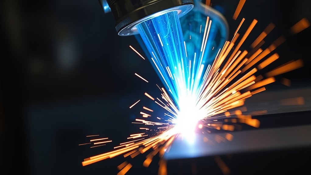
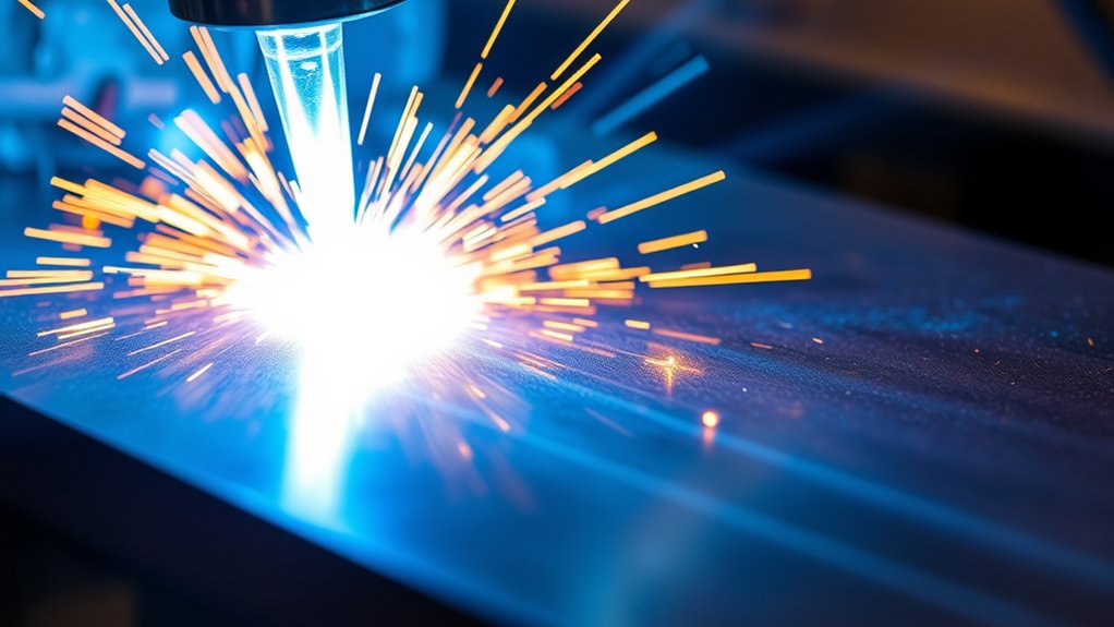
A plasma cutting arc can approach 40,000°F (about 22,000°C). That is the temperature of the hottest region in the ionized gas column. It is not the temperature of the full torch, the whole kerf, or the surrounding plate.
The cutter forces gas through a small torch opening and applies electrical energy. Part of the gas becomes ionized, which means it contains charged particles that can carry current. The narrow, high-speed jet transfers heat to the workpiece, melts a path through it, and blows molten metal out of the kerf.
Plasma cutting works only when the cutting circuit can pass current through an electrically conductive material. Common examples include mild steel, stainless steel, aluminum, copper, and brass. Wood, glass, stone, and most plastics do not complete the cutting circuit and are not suitable for standard plasma cutting.
Note: The 40,000°F figure is an arc-core estimate. You do not set “temperature” on the control panel, and the base metal does not uniformly reach that value.
A hotter arc does not automatically make a better cut. A stable arc delivered at the correct height and speed matters more than the headline temperature.
Heat moves away from the kerf through the metal. Aluminum and copper conduct heat quickly, so the machine must deliver enough energy while maintaining suitable speed and gas flow. Thin sheet can overheat or warp if the torch lingers, even though the arc is focused.
Products Worth Considering

High quality Pilot Arc Plasma Cutter torch with 4m (13ft) cable, outermost canvas wrapped.

CUTTING THICKNESS UP TO 20MM: Featuring a brand-new MCU technology upgrade, the plasma cutter machine has a high degree of internal integration, combining full digitalization for more precise control of cutting parameters such as current and voltage. This results in better cutting effects and improved stability. Cutting thickness: Quality 12mm (1/2"), maximum 20mm (3/4").

Standard length 13Ft long plasma cutting torch
Factors That Influence Plasma Arc Temperature
The arc can remain extremely hot across many settings, but the amount and concentration of heat reaching the cut changes. These controls affect arc power, energy density, stability, and how well molten metal leaves the kerf:
- Amperage: Higher current increases electrical power when the torch, nozzle, input supply, and duty cycle support it.
- Arc voltage and torch height: A longer arc generally raises voltage and spreads the energy over a larger area. A torch that is too high can produce a wider kerf and more bevel.
- Gas type: Air, oxygen, nitrogen, F5, and argon-hydrogen processes transfer heat and react with the cut edge in different ways.
- Gas pressure and flow: Correct flow shapes the arc and removes molten metal. Use the machine specification rather than guessing.
- Nozzle design and condition: The nozzle constricts and directs the arc. An enlarged, nicked, or off-center orifice can cause poor angularity and wandering.
- Travel speed: Slow travel raises heat input per inch and can create low-speed dross or a wide kerf. Excess speed can leave an incomplete cut or high-speed dross.
- Material and thickness: Thick plate needs more total energy and time to pierce. Conductivity, alloy chemistry, coating, and surface condition also affect the result.
Start with the exact cut chart supplied for your machine. A validated chart matches the material, thickness, amperage, gas, consumables, pierce height, cut height, and travel speed. Settings from another torch or power supply may not transfer safely.
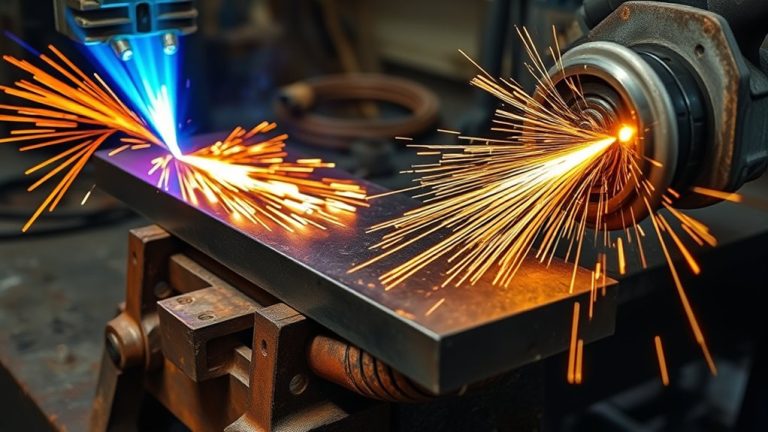
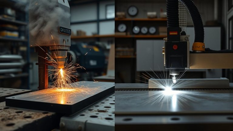
Comparing Plasma Cutting to Oxy-Fuel and Laser Cutting
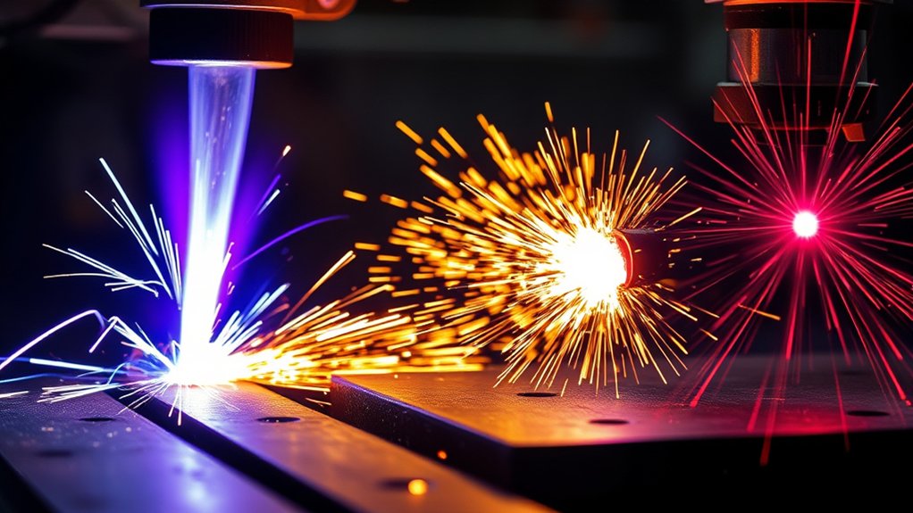
Plasma, oxy-fuel, and laser are all thermal cutting processes, but comparing them only by a single “temperature” number is misleading. An oxy-acetylene flame is commonly listed around 5,400–6,000°F, plasma uses a much hotter electrically conductive jet, and a laser concentrates light rather than producing a flame with one simple operating temperature.
The right process depends on the material, thickness, required tolerance, edge condition, production rate, and budget. The ISO 9013:2017 thermal-cutting standard, as amended in 2024, classifies geometric quality and tolerances for oxy-fuel, plasma, and laser cuts within defined thickness ranges.
| Criterion | Plasma | Oxy-Fuel | Fiber Laser |
|---|---|---|---|
| How it cuts | Arc melts metal; gas jet ejects it | Preheat plus oxygen reaction burns carbon steel | Focused light melts or vaporizes material; assist gas clears the kerf |
| Material range | Electrically conductive metals | Primarily carbon and low-alloy steels that support the oxidation process | Many metals; capability depends on laser type, power, and material |
| Typical strength | Good balance of speed, thickness range, and cost | Simple, economical cutting of thick carbon steel | Fine detail and narrow kerf, especially on thinner material |
| Main limitation | Cannot cut nonconductive material; consumables and settings affect bevel | Not suitable for stainless steel or aluminum by the normal cutting reaction | Higher capital cost and more specialized maintenance |
Choose plasma when you need fast, practical cutting across a wide range of conductive sheet and plate. Choose the process from actual machine data and part requirements, not from arc temperature alone.
Products Worth Considering

PACKAGE INCLUDED: 5 Pcs Cup-15 Pcs Electrodes-10 Pcs Ring-30 Pcs Tip(Standard)

Fit for: SG-55 AG-60 plasma cutter torch head.

Gas Choices and Their Impact on Arc Heat
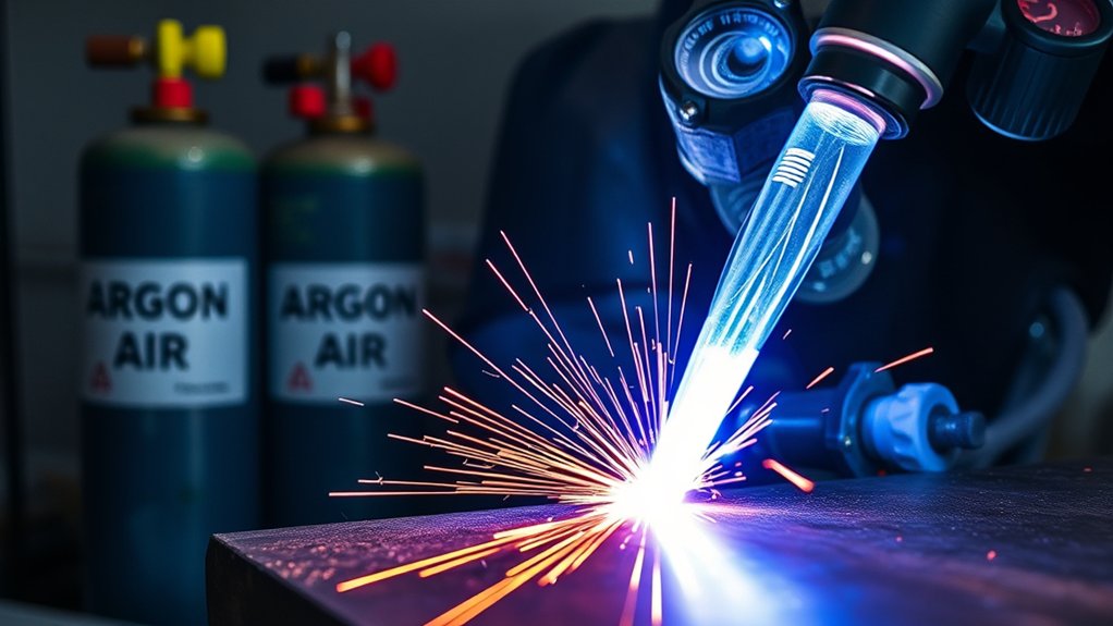
Gas chemistry changes arc behavior, cut-edge chemistry, dross, color, and speed. Some systems use one gas for both plasma and shielding, while industrial systems may use separate plasma and shield gases. Only use gases and mixtures approved for your torch and power supply.
Gas choice is a process setting, not a universal upgrade. The best option depends on the machine, material, thickness, and required edge quality.
- Compressed air: Common and economical on portable systems. It can cut mild steel, stainless steel, and aluminum when the machine supports those materials. Air can leave a more oxidized cut face and may not be the best choice when edge chemistry matters.
- Oxygen: Used by compatible industrial systems for fast, high-quality mild-steel cutting. Never feed oxygen into a machine unless the manufacturer specifically approves it.
- Nitrogen: Used on compatible systems for stainless steel and aluminum and in some broader processes. Results depend on the shield gas, thickness, and torch design; it is not automatically “oxidation-free.”
- F5: A mixture of 95% nitrogen and 5% hydrogen used by some compatible systems for thin stainless steel. Follow all gas-handling and manufacturer requirements.
- H35 or argon-hydrogen: A mixture commonly listed as 65% argon and 35% hydrogen for thicker stainless steel and aluminum on systems designed for it, often with nitrogen shielding.
The manufacturer’s gas-selection guide and cut chart should control your choice. Do not substitute gas mixtures, pressures, fittings, or regulators based on a general article.
Warning: Oxygen, hydrogen blends, and high-pressure cylinders add fire and handling hazards. Use only approved equipment, leak-test the setup as directed, secure cylinders, and follow the gas supplier and machine manual.
Machine Settings: Amperage, Nozzles, and Standoff
Machine settings control how effectively the arc’s energy reaches the metal. Use the cut chart before changing individual values. A defect that looks like “not enough heat” may actually come from excessive speed, wrong height, low gas pressure, a worn nozzle, poor work-clamp contact, or an undersized input circuit.
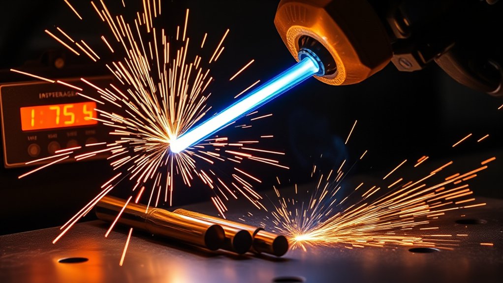
Amperage and Heat Output
Higher amperage increases available arc power, but only within the rating of the installed consumables and power supply. Do not run a nozzle above its rated current. Too much current can shorten consumable life, widen the kerf, round the top edge, and add heat without improving the cut.
- Choose the process first: Match material, thickness, consumable set, and gas.
- Set the chart amperage: Use the listed current rather than always turning the machine to maximum.
- Set speed with amperage: A higher-current process usually needs a matching travel speed.
- Respect duty cycle: A 60% rating generally means six minutes of arc-on time in a ten-minute period under the stated test conditions.
- Confirm input power: Long extension cords, weak generators, or undersized circuits can reduce performance and create hazards.
Nozzle and Standoff Control
The nozzle constricts and directs the arc. Use the exact nozzle, electrode or cartridge, shield, and retaining parts listed for the process. Never drill, file, or enlarge the orifice.
Set cut height and pierce height separately when the system requires it. Mechanized systems often pierce higher than they cut to protect the nozzle from molten spatter. Handheld drag cutting may allow the shield to touch the plate, but only with drag-rated consumables and the method listed in the manual.
- Too much standoff: The arc stretches, energy density drops, the kerf widens, and bevel may increase.
- Too little standoff: The nozzle or shield can contact spatter, overheat, or double-arc, causing rapid damage.
- Incorrect torch angle: A tilted torch produces unequal bevel and can mimic a height problem.
Pro Tip: If cut quality suddenly worsens after many good parts, inspect and replace worn consumables before changing a proven program.
Clean, Dry Gas and Consumable Condition
Portable air-plasma systems commonly require clean, dry, oil-free air at a specified flowing pressure and volume. Water, oil vapor, dirt, and pressure loss can reduce cut quality and consumable life. Drain the compressor, service filters, and add suitable drying equipment in humid conditions when the manual calls for it.
Check the nozzle orifice for an oval shape, nicks, or off-center wear. Inspect the electrode or cartridge according to the replacement limit in the manual. Replace parts as a matched process set when required; mixing worn and new parts can make troubleshooting harder.
Managing Heat Input for Precision and Speed
Precision comes from enough heat to complete the cut without keeping the arc in one place too long. Use a repeatable test-cut process instead of changing several settings at once.
- Identify the material and thickness. Remove loose scale and confirm whether the surface is coated, painted, plated, or contaminated.
- Install the listed consumables. Confirm that every part matches the process and current.
- Set gas and power. Check flowing pressure, amperage, input supply, and work-clamp contact.
- Set geometry. Hold the torch square and use the listed pierce and cut heights.
- Make a test cut at chart speed. Watch whether sparks exit the bottom and trail slightly behind the torch.
- Inspect before adjusting. Check bevel, top spatter, kerf width, drag lines, and bottom dross. Change one variable at a time.
| Cut symptom | Common causes | First checks |
|---|---|---|
| Heavy, easy-to-remove bottom dross | Travel speed too slow; current too high for the speed | Return to chart speed, then increase speed in small steps |
| Thin, hard bottom dross or incomplete cut | Travel speed too high; low power; low gas flow; worn consumables | Verify input power and gas, inspect parts, then reduce speed slightly |
| Wide kerf or rounded top edge | Torch too high; speed too slow; excessive current | Check torch height and consumable rating before changing current |
| Uneven bevel | Torch not square; worn nozzle; wrong travel direction on a CNC contour | Square the torch, inspect nozzle, and confirm cut direction |
| Misfire or wandering arc | Moist or dirty gas, poor work connection, excessive height, damaged parts | Check gas quality, clamp contact, height, and consumables |
Dross depends on several variables, including speed, amperage, standoff, material condition, and consumable wear. The manufacturer’s dross troubleshooting guidance identifies speed, amperage, and standoff as three of the most important checks.
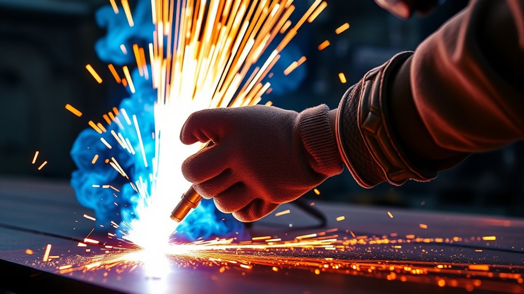
Safety Practices for Plasma Cutting
Plasma cutting combines intense ultraviolet and infrared radiation, molten metal, hot work, fumes, noise, compressed gas, and potentially lethal electrical energy. Read the machine’s safety section and follow workplace rules before striking an arc.
Warning: Never cut a sealed, pressurized, or previously used fuel or chemical container unless it has been properly cleaned, vented, tested, and approved under a qualified hot-work procedure. An empty container can still hold an explosive atmosphere.
Essential PPE and Shields
Use safety glasses with side protection under a suitable cutting helmet or face shield. Wear flame-resistant clothing that covers exposed skin, dry heat-resistant gloves, and safety boots. Avoid synthetic fabrics that can melt onto skin. Use hearing protection when noise measurements, the manual, or workplace rules require it.
Filter shade depends on current and whether the arc is clearly visible. OSHA’s plasma-arc-cutting table lists minimum shades of 8 below 300 A, 9 from 300–400 A, and 10 from 400–800 A when the actual arc is clearly seen. Follow the machine manual and employer assessment, and begin darker if needed without going below the required minimum. Eye and face devices should meet the applicable workplace requirement; the current voluntary U.S. product standard is ANSI/ISEA Z87.1-2025.
Place noncombustible screens or welding curtains so nearby people cannot view the arc or be hit by sparks. Screens must not block required ventilation or create a confined fume zone.
Ventilation and Fume Control
Capture fumes near the source with local exhaust when practical. Position the hood so it removes the plume without pulling it through your breathing zone. General shop airflow alone may not control exposure, especially in an enclosed area or when cutting coated metals.
Identify the metal and every coating before cutting. Zinc-bearing, lead-bearing, cadmium-bearing, chromium-bearing, painted, plated, or contaminated surfaces can require specific ventilation, respiratory protection, surface preparation, or industrial-hygiene controls. Do not assume a dust mask is adequate. OSHA requires local or general mechanical ventilation for several toxic-metal conditions and stricter controls for certain materials.
Never use oxygen for ventilation or to blow dust from clothing. Do not cut in a confined space without the required ventilation, attendant, rescue planning, and respiratory controls.
Fire, Electrical, and Container Safety
Move combustible materials at least 35 feet (10.7 m) from the work when practical, or protect them with suitable fire-resistant covers and guards. Check openings, walls, floors, ducts, and the opposite side of the plate for hidden combustibles. Keep the correct extinguisher ready.
OSHA requires a fire watch when conditions could allow more than a minor fire, including appreciable combustibles within 35 feet or sparks that can reach hidden areas. Where required, the watch must continue for at least 30 minutes after cutting to detect smoldering fires.
Keep the work area dry. Inspect torch leads, input cables, the work cable, and the clamp before use. Attach the clamp to clean metal as directed. Turn off and isolate input power before opening the power supply or servicing internal parts; stored electrical energy may remain, so follow the manual’s lockout and discharge instructions.
Practical Tips for Temperature Control Across Materials
Different metals move heat and react with cutting gases differently. Use these material notes only as a starting point; the machine’s cut chart remains the controlling instruction.
| Material | Heat-control focus | Practical check |
|---|---|---|
| Mild steel | Match speed and current to prevent low-speed dross and top-edge rounding | Use air on approved portable systems or the listed oxygen process on compatible industrial systems |
| Stainless steel | Control gas and speed to limit roughness, color, and edge chemistry changes | Use only the approved air, nitrogen, F5, or argon-hydrogen process for the thickness |
| Aluminum | Account for fast heat conduction and distortion in thin sheet | Keep the torch moving, support the sheet, and use the approved air, nitrogen, or argon-hydrogen process |
| Copper and brass | High thermal conductivity can demand more power than the same thickness of steel | Confirm that the machine has enough rated capacity and use its nonferrous cut chart |
| Thin sheet | Limit dwell time, warping, and a wide heat-affected zone | Use lower-current or fine-cut consumables when listed and keep travel smooth |
Before production cutting, set amperage from the chart, verify flowing gas pressure, hold the torch square, and make a test cut. Inspect the edge before changing anything. Small changes in speed or height often solve a defect better than a large current change.
Pro Tip: Record the machine, consumable part numbers, gas, pressure, amperage, height, speed, material grade, and thickness for every successful process. A simple cut log makes future setup faster and more repeatable.
Frequently Asked Questions
Does the metal itself reach 40,000°F?
No. The figure describes the hottest region of the plasma arc. A narrow zone of metal melts and is blown from the kerf, while nearby metal reaches lower temperatures. Heat input, travel speed, material thickness, and thermal conductivity control the size of the heat-affected zone.
How does ambient humidity affect plasma arc stability?
Humidity matters mainly when it adds moisture to a compressed-air supply. Water, oil, and dirt in the gas line can reduce cut quality and consumable life. Drain the compressor, service separators and filters, and use a suitable dryer in humid conditions when the machine manual recommends one.
Can arc heat damage CNC electronics nearby?
Yes. Hot slag, sparks, metal dust, and radiant heat can damage exposed controls, sensors, and cables. Plasma systems can also create electrical noise. Follow the table and plasma-system manuals for grounding, bonding, cable separation, shielding, and enclosure placement instead of adding improvised grounds.
What infrared PPE is recommended beyond standard face shields?
Use a cutting helmet or face shield with the correct filter shade, plus safety glasses with side protection underneath. Add flame-resistant clothing, dry gloves, and full skin coverage. Do not choose eyewear from an “infrared-rated” label alone; select marked equipment that meets the applicable standard and shade requirement for the current.
How does duty cycle relate to sustained arc temperature?
Duty cycle limits arc-on time before the power supply needs cooling. A 50% duty cycle usually means five minutes of cutting in a ten-minute period at the stated amperage and test temperature. Lower current may increase duty cycle. Follow the exact rating plate and manual because ambient temperature and operating conditions matter.
Are there heat-related effects on cut-edge metallurgical phases?
Yes. Rapid heating and cooling can change hardness, microstructure, residual stress, and surface chemistry near a cut edge. The effect depends on alloy, gas, speed, and heat input. Critical parts may require a qualified cutting procedure, hardness checks, machining, grinding, or other edge preparation before welding or coating.
Can a plasma cutter cut nonconductive materials?
A standard plasma cutter cannot cut wood, glass, stone, or most plastics because the workpiece must carry the cutting current. Laser, waterjet, saw, router, or abrasive methods may be better for nonconductive materials.
Why do I get dross if the plasma arc is so hot?
Dross is not simply a sign of low temperature. It can come from travel that is too slow or too fast, wrong standoff, incorrect amperage, weak gas flow, worn consumables, or material condition. Return to the cut chart and change one variable at a time.
What Temperature Is Best for Plasma Cutting?
You do not select an arc temperature directly. The best process is the one listed for your material and thickness that produces full penetration, acceptable bevel, a controlled kerf, and little removable dross without exceeding the machine’s duty cycle.
If the edge overheats, do not assume that current is the only cause. Check travel speed, cut height, nozzle condition, gas flow, and whether the process is oversized for the material. If the cut does not penetrate, verify input power, gas pressure while flowing, work-clamp contact, consumables, and speed before raising current.
Conclusion
A plasma cutter’s arc can approach 40,000°F, but the workpiece never reaches that temperature throughout. The useful question is not “How hot can it get?” but “How well is the arc’s energy being delivered to this material?”
Begin with the manufacturer’s cut chart. Match the consumables, gas, amperage, pierce height, cut height, and speed, then make a test cut and adjust one variable at a time. Pair that process control with correct eye protection, local exhaust, clean gas, electrical precautions, and a complete hot-work plan for cleaner cuts and a safer shop.
Sources
- Hypertherm: What Is a Plasma Cutter? — plasma arc temperature and cutting process
- Hypertherm: Plasma Gas Selection Guide — approved gas families and material uses
- Hypertherm: Basic Tips to Improve Plasma Cut Quality — cut charts, consumables, height, gas, and speed
- OSHA 29 CFR 1910.252 — hot-work fire prevention, 35-foot control area, and fire-watch requirements
- OSHA 29 CFR 1915.153 — plasma arc cutting filter-shade guidance and eye protection
- OSHA 29 CFR 1926.353 — ventilation, confined-space controls, and toxic-metal cutting hazards