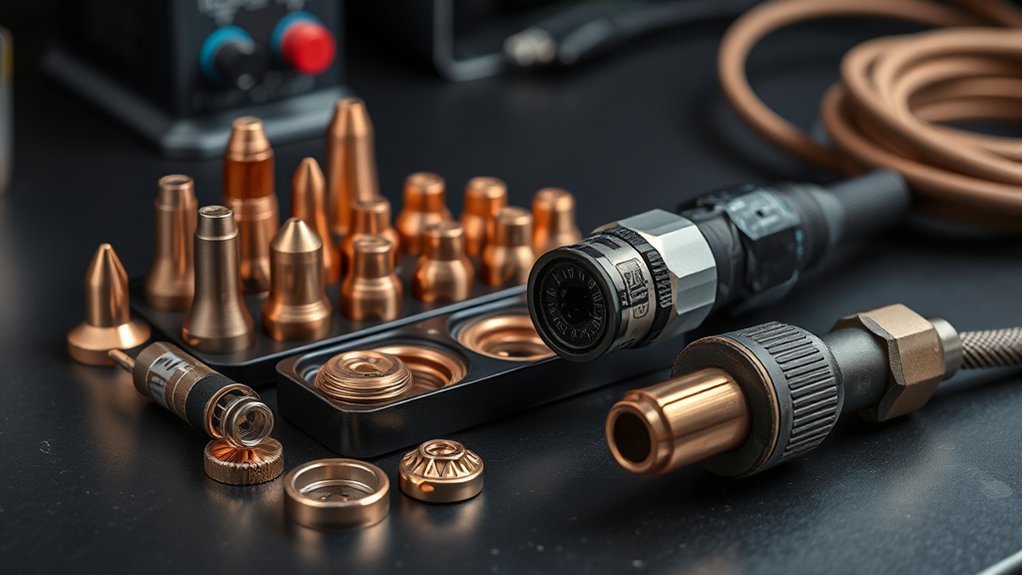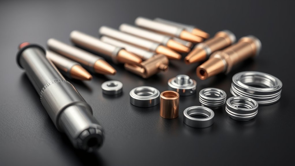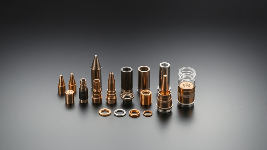
Poor plasma cuts often begin before the arc starts. A nozzle, electrode, shield, swirl ring, or retaining cap that does not match the torch can cause dross, bevel, misfires, a wide kerf, and rapid wear. The safest approach is to identify the exact torch, use its current cut chart, install the complete matched consumable stack, and verify the setup on scrap.
Quick Answer
Choose plasma cutter consumables by identifying the exact torch model, then matching the approved part numbers, process, nozzle amperage, material, thickness, gas, and torch-height settings in its cut chart. Never mix look-alike parts. Check air quality and wear, install the stack cleanly, and test on scrap before production.
Key Takeaways
- Start with the torch model and the manufacturer’s current consumable diagram and cut chart.
- Choose a complete, compatible set for cutting, gouging, marking, drag cutting, or mechanized work.
- Use the charted nozzle amperage, gas flow, speed, cut height, and pierce height rather than generic settings.
- Keep compressed air clean, dry, oil-free, and within the required pressure and flow range.
- Inspect each part against the maker’s wear limits and replace it before it damages the rest of the torch.
At a Glance
| Time Required | About 15–30 minutes to identify, inspect, install, and test a consumable set |
| Difficulty | Easy to moderate; exact part-number matching is more important than mechanical skill |
| Tools Needed | Owner’s manual or cut chart, clean lint-free cloth, good lighting, approved inspection gauge if specified, and scrap metal |
| Cost | Inspection costs nothing; replacement cost depends on the torch, process, and approved consumable set |
Warning: Turn the plasma cutter off, unplug it or follow your workplace lockout procedure, isolate the gas supply, and let the torch cool before touching consumables. Plasma cutting also creates ultraviolet radiation, hot metal, sparks, fumes, noise, and electrical hazards, so use the eye, face, hand, hearing, clothing, and ventilation protection required by the machine manual and your workplace.
Match Consumables to Your Owner’s Manual and Cut Charts
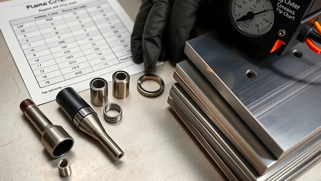
Before you load the torch, identify the power supply, torch family, torch model, and whether it is a handheld or machine torch. Then compare every part number with the consumable diagram in the current owner’s manual. A complete set may include an electrode, nozzle, swirl ring, shield or deflector, and retaining cap. Similar-looking parts from another torch family may fit poorly, alter gas flow, or prevent the cap sensor from working.
The cut chart should remain your main reference. It connects the consumable set to the material, thickness, process, arc current, gas type, gas pressure or flow, travel speed, cut height, pierce height, and arc voltage. Hypertherm’s official Powermax cut-quality troubleshooting guide, for example, directs operators to select the correct consumables for the application and notes that nozzle selection by amperage affects cut quality and speed.
Fine-tune only after the charted setup produces a stable baseline. Alloy differences, mill scale, paint, rust, coatings, air quality, and plate flatness can change the final result. Record the successful settings so the next job starts from proven data rather than guesswork.
What Each Consumable Does
| Part | Main Job | Common Wear Clues |
| Electrode | Carries the arc and contains the emitting insert used by that torch design | Pit reaches the OEM limit, off-center wear, cracking, or severe discoloration |
| Nozzle | Constrains and shapes the plasma jet through a precise orifice | Orifice becomes oval, enlarged, nicked, burned, or rough |
| Swirl ring | Controls gas direction and centers the arc within the nozzle | Cracks, blocked holes, erosion, warping, or damaged locating features |
| Shield or deflector | Protects the nozzle and provides the standoff, drag, or sensing function specified by the torch | Spatter buildup, cracks, burned holes, damaged threads, or distorted face |
| Retaining cap | Holds the stack in position and may support sensing or coolant flow | Cracks, thread damage, leaks, carbon tracking, or poor seating |
Note: Part names and stack order vary by torch. Some newer systems use a single-piece cartridge instead of separate electrodes, nozzles, swirl rings, and shields. Follow the diagram for your exact system.
How to Choose Plasma Cutter Consumables Step by Step
- Identify the exact torch. Find the model on the torch body, lead label, power supply, or manual. Do not shop by machine amperage alone.
- Choose the process. Decide whether you are cutting, gouging, marking, drag cutting, flush cutting, or using a mechanized table.
- Confirm material and thickness. Use the chart for mild steel, stainless steel, aluminum, or the material supported by the machine.
- Select the complete part-number stack. Match the electrode, nozzle, swirl ring, shield or deflector, and retaining cap as one approved system.
- Set the charted current and gas. Use the nozzle’s listed amperage with the required pressure and flow. Confirm the compressor can supply the needed flow while cutting.
- Install the parts cleanly. Check orientation, O-rings, threads, seating surfaces, and cap tightness without forcing anything.
- Set height, speed, and voltage. Use the cut chart’s cut height, pierce height, delay, travel speed, and arc voltage when applicable.
- Make a test cut and log the result. Inspect dross, edge angle, kerf, lag lines, top spatter, and penetration before cutting a finished part.
A plasma torch is a matched flow-and-geometry system. The correct nozzle cannot compensate for the wrong electrode, swirl ring, shield, gas setting, or torch height.
Choose Nozzle Size by Amperage Rating and Material Thickness
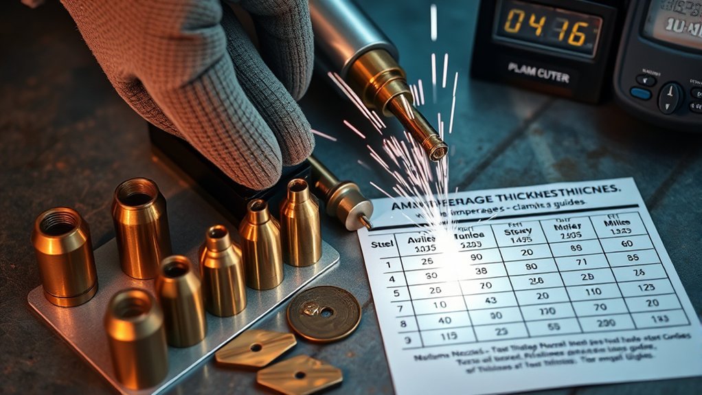
Nozzle selection begins with the cut chart, not a universal hole-size rule. The orifice is engineered for a specific current range, gas flow, and torch design. Running a nozzle above its rating can enlarge or distort the orifice. Running a high-amp nozzle far below its intended current can produce a weak, poorly focused arc and heavy dross.
For thin sheet, use the lower-amperage or fine-cut consumable set listed by the manufacturer. This usually gives a narrower kerf and lower heat input than trying to turn down a larger nozzle without chart support. For thicker plate, move to the charted higher-amperage set only if the power supply and torch are rated for it.
Material thickness is only one input. The chart may specify different sets for hand cutting, mechanized cutting, expanded metal, gouging, or marking. It may also list separate parameters for mild steel, stainless steel, and aluminum.
Products Worth Considering

[Achieve Precise Cuts] PT31 Plasma Cutting Consumables – Your Essential Tool for Efficient Cutting! Whether you're working with sheet metal, steel, or any other material, superior cutting performance ensure clean, accurate, and smooth cuts.
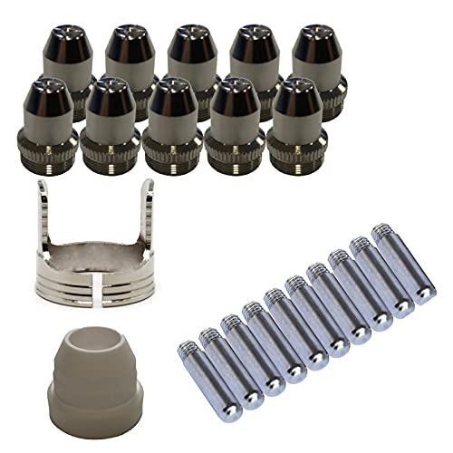
Only Compatible with BROWN Color Lotos LTP5800D , LTP5000D, LTPDC2000D.

Fit for: SG-55 AG-60 plasma cutter torch head.
Match the Consumable Set to the Job
| Job | Consumable Direction | What to Verify |
| Thin sheet or fine detail | Lower-amp or fine-cut set if offered | Minimum supported thickness, speed, height, and material type |
| General handheld cutting | Standard shielded, drag, or standoff set specified for the torch | Whether the shield may touch the plate and the required current |
| CNC or mechanized cutting | Machine-torch set with the required sensing cap or shield | Pierce height, cut height, delay, voltage, speed, and ohmic compatibility |
| Gouging | Dedicated gouging nozzle and shield | Gouge profile, current, torch angle, and gas setting |
| Flush, extended-reach, or close-profile work | Only the special set approved for that torch | Output limits, accessibility, and reduced protection from impact or spatter |
| Marking | Marking consumables and gas process if the system supports them | Marking current, gas, speed, and whether cutting parts must be removed |
Select the Electrode Design Specified for Your Torch
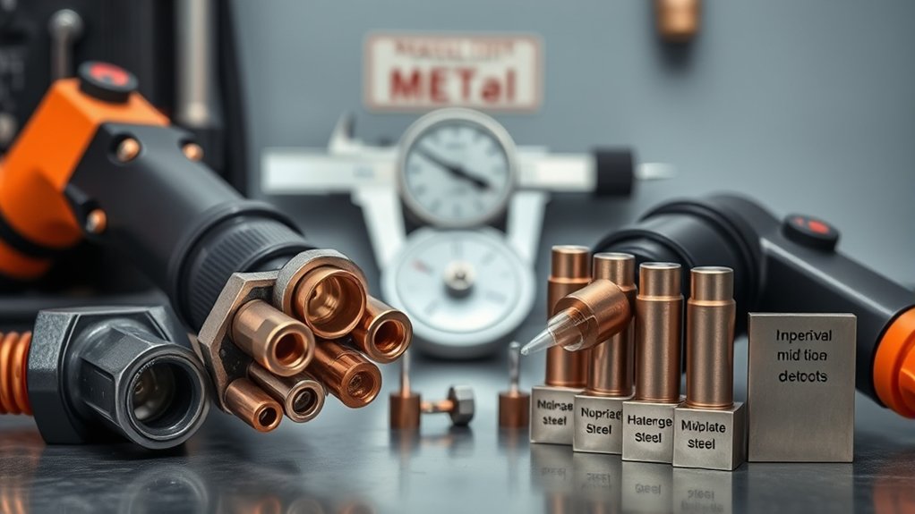
Do not choose an electrode by metal description alone. Most air-plasma electrodes use a copper body with an emitting insert, often hafnium, but the geometry, cooling path, and wear limit are specific to the torch. Some mechanized systems offer silver-front-end designs around the hafnium interface. Hypertherm explains that its SilverPlus electrode technology transfers heat differently and permits a deeper usable pit than its standard copper design, but that benefit applies only to listed systems and part numbers.
Use the exact electrode in the consumable diagram for the selected amperage and gas process. A silver-interface electrode is not a universal upgrade, and a standard copper-bodied electrode is not limited to low-current work. Compatibility, cooling, and the approved wear limit matter more than the broad material category.
Inspect the pit for depth, centering, cracking, and abnormal discoloration. Measure it only with the gauge or method the manufacturer approves. Off-center wear can point to a damaged swirl ring, incorrect assembly, contaminated gas, cooling trouble, or a mismatched nozzle.
Shielded vs. Unshielded Consumables
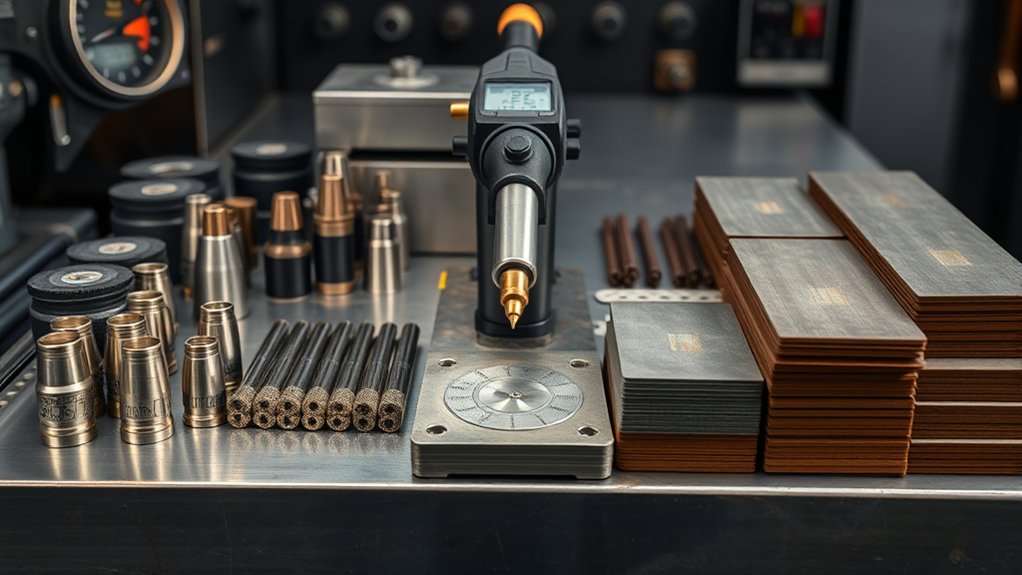
Shielded and unshielded sets are not interchangeable labels for “CNC” and “handheld.” A shielded set places an additional component around the nozzle and may support drag cutting, spatter protection, a controlled standoff, or an electrical sensing path. An unshielded set exposes the nozzle or uses a deflector arrangement. Either style must be specifically approved for the torch and process.
Choose the exact shield, deflector, or retaining-cap arrangement shown in the consumable diagram. Changing only the front cap can alter gas flow, torch-to-work distance, sensing behavior, and nozzle cooling.
Ohmic Sensing Compatibility
Ohmic initial-height sensing works only when the CNC, torch, wiring, and front consumable provide the electrical path required by that system. Some torches use an electrically conductive shield or ohmic retaining cap. Others use a separate ohmic ring, and some tables use mechanical, magnetic, or pressure-based sensing instead.
- Verify the torch-height controller and sensing method before ordering consumables.
- Use the exact ohmic-capable shield, retaining cap, or ring listed for the torch.
- Keep the contact surface clean because paint, rust, water, oil, and spatter can interrupt probing.
- Do not assume every shielded consumable supports ohmic sensing.
- Do not substitute an unshielded part unless the manual shows that configuration.
Standoff and Dross Control
Use drag consumables only when the manufacturer allows the shield to touch the work. Otherwise, hold the charted standoff with a guide, steady hand, or torch-height control. Running too high can widen the kerf and increase bevel; running too low can expose the nozzle to spatter, double arcing, and molten blowback.
On a CNC table, calibrate initial height sensing and torch-height control before production. On a handheld cut, keep the torch square to the plate and move at a steady speed. Shield choice, height, speed, current, and air flow work together, so changing one variable may not solve dross by itself.
Set Amperage to the Nozzle Rating
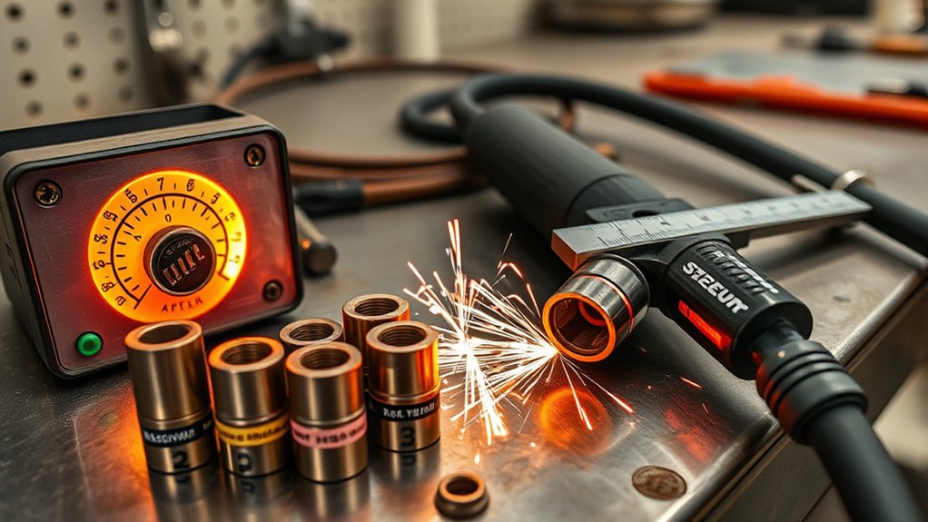
Set the machine to the current shown for the selected nozzle and cut chart. Do not assume that more amperage will improve penetration or that a larger nozzle will last longer on thin material. The nozzle, electrode, gas flow, and cooling system are designed to work together at the listed output.
Match Amps to the Complete Consumable Set
- Confirm the nozzle’s part number and rated current before powering the torch.
- Use the matching electrode, swirl ring, shield, and retaining cap.
- Set the charted current for the material and process.
- Replace a worn nozzle before changing parameters to chase a bad cut.
- Record material, thickness, current, pressure, speed, height, and results.
Risks of Overamping
Current above the nozzle’s rating can overheat the nozzle, enlarge the orifice, shorten electrode life, destabilize the arc, and increase the chance of damage to nearby torch parts. The visible result may be a wider kerf, rougher edge, heavy dross, irregular bevel, or a sudden change in arc sound.
Lincoln Electric’s guidance on improving plasma consumable life also emphasizes keeping pressure close to the machine specification because both excessive and insufficient pressure can accelerate different wear modes.
Use a Lower-Amp Consumable Set Instead of Guessing Low
A small current reduction may be allowed on some machines and charts, but “slight underamping” is not a universal thin-sheet rule. If the machine offers a dedicated lower-amperage nozzle or fine-cut set, use it. That keeps the orifice, gas flow, and current density matched.
- Start at the charted current rather than an arbitrary reduced setting.
- Move to a lower-amp consumable set when the chart offers one.
- Reduce current only within the range specifically allowed by the manufacturer.
- Reject any setting that causes incomplete penetration, a trailing arc, heavy dross, or an unstable sound.
- Document a successful test-cut setting before production.
Warning: Never force a nozzle above its rated current or combine a high-current nozzle with an unapproved electrode, shield, or swirl ring. A damaged torch body costs far more than a correct consumable set.
Dial In Cut Height, Pierce Height, and Arc Voltage
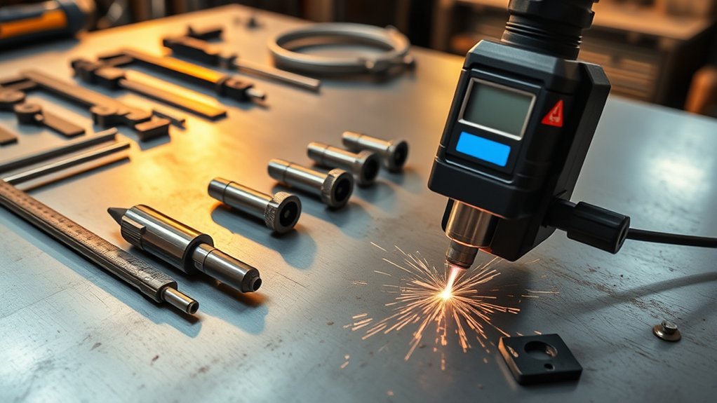
Torch-to-work distance affects edge angle, dross, kerf width, and consumable life. For mechanized cutting, set three separate values when the cut chart provides them: pierce height, cut height, and arc voltage. Pierce height is commonly higher than cut height so molten metal is less likely to blow back into the nozzle during the pierce.
After the pierce delay, the torch should move to the programmed cut height before the contour begins. Torch-height control then uses arc voltage to maintain arc length while the plate moves or warps. Use the charted voltage as the baseline and make only small changes after confirming the nozzle, electrode, speed, current, and plate height are correct.
For handheld cutting, follow the shield’s drag or standoff instructions and keep the torch square. Excessive bevel can come from height, speed, torch angle, worn consumables, or the natural “good side/bad side” direction of a plasma arc, so inspect the whole setup rather than changing height alone.
Note: Arc voltage is mainly a mechanized torch-height-control setting. Do not apply a generic voltage number to a handheld torch or to a different consumable set.
Air and Coolant Quality: Pressure, Flow, and Cooling
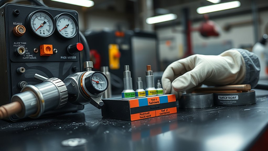
Good consumables cannot correct a weak or contaminated gas supply. Set pressure at the location and under the conditions specified by the manual. A gauge can show adequate static pressure while pressure and flow collapse as soon as the torch opens, so verify the supply while gas is flowing.
- Use clean, dry, oil-free compressed air when the system is designed for air plasma.
- Drain the compressor and water separator and service filters on schedule.
- Confirm the compressor’s delivered flow at the required pressure, not only its tank size.
- Check hoses, fittings, regulators, and filters for restrictions or leaks.
- For liquid-cooled torches, use the specified coolant and verify level, pump operation, flow, hoses, filters, and strainers.
Moisture, oil, particles, low flow, and excessive pressure can change arc behavior and accelerate wear. Hypertherm’s common plasma-cutting mistakes guide identifies contaminated gas, poor flow, and incorrect pressure as common causes of short consumable and torch life.
Pro Tip: If cut quality changes suddenly across every material, check air moisture, pressure under flow, and a partially blocked filter before replacing several consumables at once.
Install Consumables Correctly and Protect O-Rings
Installation errors can imitate worn parts. Work on a clean surface with clean hands or gloves so metal dust, grinding grit, oil, and excess lubricant do not enter the torch. Check the manual for the correct stack order and orientation.
- Shut down the machine, isolate energy and gas, and let the torch cool.
- Remove the retaining cap without using pliers unless the manual specifically calls for a tool.
- Lay the parts on a clean lint-free cloth in removal order.
- Inspect threads, seating surfaces, O-rings, and the torch cavity for damage or contamination.
- Install the swirl ring, electrode, nozzle, shield or deflector, and cap in the sequence shown for the torch.
- Tighten the retaining cap only as directed. Do not force cross-threaded or misaligned parts.
- Apply only the approved O-ring lubricant when required. Use a film thin enough to leave a shine, then wipe away visible excess.
- Reconnect power and gas, run the system’s gas test if available, and check for faults or leaks before cutting.
Do not use petroleum grease or general-purpose shop grease inside the torch. Excess or unapproved lubricant can trap conductive dust, disturb gas flow, and contribute to internal arcing. The manufacturer’s lubricant and quantity take priority.
Inspect, Measure, and Replace Worn Consumables
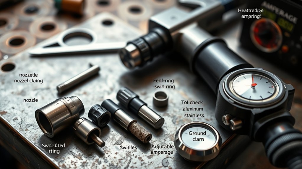
Use objective wear limits rather than waiting for a failed cut. Inspect consumables at a frequency that fits your work: before an important job, after a crash or misfire, when cut quality changes, or at a set number of starts or arc-on minutes.
Electrode Wear
Check pit depth, centering, cracking, and discoloration. Replace the electrode at the exact limit listed for that design. Copper-bodied and silver-front-end electrodes can have very different usable pit depths, so never transfer a limit from another family.
Nozzle Wear
Look at the orifice under good light or magnification. It should remain round with clean, sharp edges. Replace it if the opening is enlarged, oval, nicked, gouged, or burned. Do not force a pin, drill, wire, or cleaning tool through the orifice. Use a dimensional gauge only when the manufacturer approves that method.
Shield, Swirl Ring, and Cap Wear
Remove spatter only with the method allowed by the manual. Replace cracked, distorted, burned, or badly eroded shields. Inspect the swirl ring for blocked gas holes, cracks, chipping, warping, and damaged locating features. Check the retaining cap for thread damage, leaks, carbon tracking, and poor seating.
You do not always need to replace the electrode and nozzle as a pair. Inspect each part and follow the manufacturer’s replacement policy. Pair replacement may make sense when both parts have reached similar wear, after a severe failure, or when the system uses a single-piece cartridge.
Note: Continuing to run an electrode past its limit can cause rapid failure that damages the nozzle, shield, retaining cap, torch body, and workpiece.
Kerf Width and Speed: Optimize for Quality and Cost
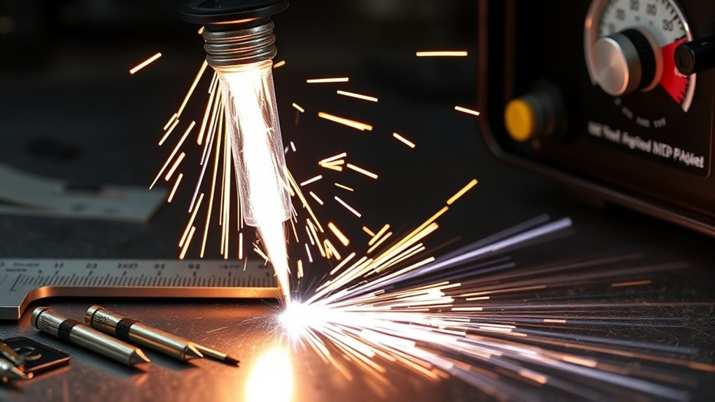
Kerf is the material removed by the plasma arc. It changes with the nozzle, amperage, material, thickness, speed, height, gas, and consumable wear. Treat it as a measured process value rather than a fixed number copied from another machine.
On a CNC table, enter the measured kerf compensation in the computer-aided design and computer-aided manufacturing (CAD/CAM) setup. Use test coupons to verify finished dimensions, hole quality, edge angle, and lead-in behavior. For handheld work, account for the kerf when placing a guide or cutting to a line.
- Start with the material-specific cut-chart speed.
- Keep the torch square and at the charted height.
- Use the listed current, gas, and voltage for that consumable set.
- Adjust speed in small steps after checking part wear and air quality.
- Measure the finished part and update the setting log when the result is repeatable.
A valid setup reduces scrap and secondary grinding, but the fastest clean cut is not always the lowest cost. Track acceptable parts per set, arc-on time, and changeout labor to understand the real cost per cut.
Troubleshoot Cut Quality Before Buying More Parts
Consumables are a common cause of poor results, but they are not the only cause. Use the symptom as a starting point, then inspect the matched set, settings, air supply, torch motion, work lead, and material condition.
| Symptom | Check First | Useful First Action |
| Misfire or hard starting | Cap seating, electrode/nozzle wear, pressure, moisture, work lead, and start circuit | Reassemble the correct clean stack and verify pressure under flow |
| Heavy bottom dross | Travel speed, current, height, worn nozzle, air flow, and material limits | Return to the charted speed and current, then make one small speed change at a time |
| Top spatter or nozzle damage | Pierce height, pierce delay, cut height, and starting too close to the plate | Restore the charted pierce sequence and inspect the shield and nozzle |
| Excessive bevel | Torch squareness, cut direction, height, speed, nozzle wear, and plate movement | Square the torch and test with a new or verified nozzle at charted height |
| Wide or changing kerf | Nozzle orifice, height, speed, current, and torch motion | Inspect the nozzle and verify standoff before changing CAD/CAM compensation |
| Very short consumable life | Wrong parts, contaminated gas, pressure error, cooling, overamping, edge starts, and shutdown sequence | Confirm part numbers, air quality, pressure, and the approved start/stop process |
| Double arcing or internal tracking | Low standoff, spatter, wrong assembly, damaged insulation, dirty torch, and excess lubricant | Stop cutting, shut down the system, and inspect the entire front end before reuse |
OEM vs. Third-Party Plasma Consumables
The safest baseline is the original equipment manufacturer’s approved part number because the cut chart, cooling path, gas flow, electrical clearances, and wear limits were developed around that geometry. A third-party part may be usable if its maker clearly lists the exact torch compatibility and the full matching stack, but appearance alone is not proof.
- Do not mix parts from different consumable families unless the torch maker approves the combination.
- Compare exact part numbers, revision notes, amperage, gas process, and torch model.
- Check whether third-party parts affect the machine or torch warranty.
- Reject parts with damaged threads, rough or off-center orifices, poor plating, missing markings, or inconsistent dimensions.
- Validate any new source with test coupons and a documented life and cut-quality comparison.
Compatibility matters more than brand loyalty. A precisely made approved set is valuable because it keeps the gas path, electrical path, and mechanical stack within the torch’s design.
Products Worth Considering

⚡【Precision Compatibility】 Exact fit for YESWELDER CUT 55DS Pro & 65DS (2019-2024 models). Replaces OEM# IPT40-55DS/65DS.

Can only be used for BROWN Color Lotos LT5000D and BROWN Color Lotos CT520D

Fit for : AG-60 AG-60P SG-55 WSD-60 Plasma cutter torch head
Store and Track Consumables for Lower Cost per Cut
Store clean consumables in labeled, closed containers away from grinding dust, moisture, oil, and impact. Keep different torch families and amperages in separate bins so look-alike parts cannot be mixed during a fast changeout. Sealed bags or bins with desiccant can help in humid shops, provided the parts remain clean and dry.
Track part number, material, thickness, amperage, starts, arc-on time, failure reason, and acceptable parts produced. A simple cost-per-part calculation is more useful than judging a consumable only by purchase price:
Consumable cost per acceptable part = total consumable-set cost ÷ number of acceptable parts produced.
If a set fails early, record whether the cause was normal wear, a pierce error, a crash, contaminated air, a cooling fault, or a mismatched part. This turns replacement history into a maintenance tool.
Common Mistakes When Choosing Plasma Cutter Consumables
Many cut-quality problems come from small selection and setup errors. Avoid these common mistakes:
- Mixing electrodes, nozzles, shields, retaining caps, or swirl rings from different torch families.
- Choosing parts by appearance instead of the exact part-number diagram.
- Using one nozzle size for every material thickness and process.
- Running a low-amp nozzle above its rating or a high-amp nozzle far below its intended range.
- Using wet, oily, dirty, or low-flow compressed air.
- Assuming every shielded part supports ohmic sensing.
- Installing parts in a dirty torch or using too much O-ring lubricant.
- Piercing at cut height and exposing the nozzle to molten blowback.
- Waiting for severe dross or misfires before inspecting consumables.
- Changing several settings at once instead of returning to the cut chart and testing one variable at a time.
Frequently Asked Questions
How do ambient temperature and humidity affect consumable life?
Humidity matters mainly because compressed air can carry more water into the plasma system. Moisture, oil, and particles can disturb the arc and accelerate electrode and nozzle wear. Drain the compressor, maintain separators and dryers, and store spare parts in clean, dry containers. Very hot conditions can also reduce cooling margin, so keep vents and coolant systems clear.
Are there consumables optimized for CNC versus handheld cutting?
Yes. Machine-torch sets may be designed for repeatable pierces, torch-height control, ohmic sensing, and consistent kerf. Handheld sets may support drag cutting, better visibility, or extended reach. Use the exact consumable diagram and cut chart for the torch style rather than moving parts between a hand torch and machine torch.
What storage conditions prevent nozzle and electrode corrosion?
Keep consumables in labeled, closed bins or sealed bags in a clean, dry area. Use desiccant in humid shops and keep the parts away from oil, coolant, grinding dust, and bare-hand contamination. Do not toss precision nozzles into an open drawer where the orifice or threads can be damaged.
Can different swirl rings alter dross and edge angularity?
Yes. The swirl ring controls gas direction and helps center the arc. The wrong ring, blocked holes, cracks, or damaged locating features can disturb gas flow and produce off-center electrode wear, bevel, unstable starts, or dross. Match the ring to the torch, amperage, gas, and complete consumable set.
How do duty-cycle limits influence consumable selection?
Duty cycle limits how long the power source can operate at a stated output before it must cool. It does not replace the consumable chart. Use the set specified for the selected amperage and process, keep cooling and airflow within specification, and stop when the machine reaches its duty-cycle limit.
Can I mix OEM and aftermarket plasma consumables?
Do not mix parts merely because they look alike. Use a complete set whose manufacturer explicitly lists compatibility with your exact torch, amperage, and process. Confirm warranty implications and test the set on scrap. Never combine parts from unrelated families unless the torch maker approves that combination.
Should I replace the electrode and nozzle at the same time?
Not always. Inspect each part against its own wear limit. Replace both after a severe failure, when both are near end of life, when the manufacturer recommends pair replacement, or when the system uses a single-piece cartridge. Replacing a good nozzle automatically can raise cost without improving the cut.
What causes double arcing in a plasma torch?
Common causes include cutting too close with a non-drag setup, molten spatter bridging the shield and nozzle, dirty or misassembled consumables, damaged insulation, excessive lubricant, and worn parts. Stop cutting, shut down the system, and inspect the entire torch front end before restarting.
Conclusion
Choosing plasma cutter consumables is a matching process, not a guess based on shape or machine amperage. Identify the exact torch, choose the process and material, install the complete approved stack, and use the cut chart for current, gas, speed, and height. Keep the air clean, inspect wear before failure, and test one change at a time. A short settings and life log will improve repeatability, reduce scrap, and show which consumable set delivers the lowest real cost per acceptable part.
Sources
- Hypertherm Powermax Cutting Troubleshooting Guide — consumable selection, nozzle amperage, assembly, air flow, and cut-quality checks
- Hypertherm: 10 Common Plasma Arc Cutting Mistakes — torch assembly, O-ring lubrication, gas quality, cooling, and maintenance
- Hypertherm SilverPlus Electrode Technology — silver/hafnium interface design and system-specific wear benefits
- Lincoln Electric: Tips on Improving Plasma Torch Consumable Life — pressure, airflow, assembly, starts, and consumable wear
- Miller: How to Select and Operate a Hand-Held Plasma Cutter — capacity, cut quality, air supply, and operating considerations
- OSHA: Welding, Cutting, and Brazing Hazards and Solutions — fumes, ultraviolet radiation, burns, electrical shock, and PPE