Weak or contaminated airflow can turn a clean plasma cut into a rough edge, unstable arc, and short consumable life. Your plasma cutter needs enough airflow at the specified working pressure, along with dry, oil-free air and leak-free connections. This guide shows you how to size the compressor, connect the air line, add filtration, set working pressure, test the system, and cut more safely.
Quick Answer
To hook up a plasma cutter to an air compressor, match the compressor’s delivered CFM or SCFM at the pressure listed in the cutter manual. Connect a properly rated air hose, install moisture and particle filtration, set pressure while air is flowing, check for leaks, and make a test cut on scrap metal.
Key Takeaways
- Match both airflow and pressure. Reaching the correct PSI does not help if the compressor cannot maintain the cutter’s required CFM or SCFM.
- Rate every hose, fitting, filter, and regulator above the maximum pressure that the compressor can supply.
- Feed the cutter clean, dry, oil-free air. Drain the tank and use suitable moisture and particle filtration.
- Adjust working pressure while air is flowing through the cutter, not from the compressor’s static tank-pressure reading.
- Bleed trapped pressure before removing a fitting, wear proper PPE, control fumes and sparks, and test the setup on scrap metal.
At a Glance
| Time Required | 15 to 30 minutes for a basic connection and leak test |
| Difficulty | Beginner to intermediate |
| Tools Needed | Air compressor, rated hose, compatible fittings, filter or separator, regulator, wrenches if required, and leak-detection solution |
| Cost | No added cost when compatible components are included; otherwise, cost varies by hose, fittings, filtration, and dryer requirements |
What’s in This Article
- What You Need Before You Start
- Step 1: Select the Right Hose and Fittings
- Step 2: Connect the Compressor to the Plasma Cutter
- Step 3: Install Moisture Filtration and a Regulator
- Step 4: Set the Correct Working Pressure
- Ensure Good Cutting Performance
- Safety Precautions and Best Practices
- Common Mistakes and Troubleshooting
- Frequently Asked Questions
- Safety Disclaimer
- Sources
- Conclusion
Estimated total time: 15 to 30 minutes for a basic setup, plus additional time if you need adapters, a larger hose, extra filtration, or an air dryer.
What You Need Before You Start
Before you connect anything, find the air-supply section in your plasma cutter manual. Write down the required airflow and inlet pressure. Airflow may appear as CFM, SCFM, liters per minute, or cubic meters per hour. Compare that requirement with the compressor’s delivered airflow at the same PSI.
For example, the current Hypertherm Powermax45 SYNC specification calls for clean, dry, oil-free gas at 6.7 SCFM and 90 PSI. That figure is an example, not a universal setting for every plasma cutter.
Gather the following parts and safety equipment:
- Plasma cutter with its correct air-inlet fitting
- Air compressor that can maintain the cutter’s required CFM or SCFM at the specified PSI
- Rated air hose with enough internal diameter for the required flow and hose length
- Quick-connect or threaded fittings that match both machines
- Air-pressure regulator if the compressor or cutter does not provide suitable regulation
- Moisture separator, particulate filter, or air dryer selected for the required airflow
- Oil-removal or coalescing filtration when the air supply may contain compressor oil
- Thread sealant approved for the fitting type, when required
- Compatible leak-detection solution
- Safety glasses, welding helmet, hearing protection, gloves, and flame-resistant clothing
Warning: Switch off and unplug the plasma cutter before installing or changing air fittings. Close the compressor outlet and bleed trapped pressure from the hose before loosening any connection.
Products Worth Considering

【Large Digital Display】The upgraded LED interface clearly displays key parameters such as air pressure, voltage, current, and working status in real time, allowing users to monitor machine performance and make timely adjustments for more efficient operation. If an issue occurs, the screen shows an error code to help quickly identify the problem and simplify troubleshooting.


【Product Name】1/4" NPT Air Pressure Filter/Regulator Unit
Check CFM, PSI, and Duty Cycle
A compressor’s maximum PSI tells you how much pressure it can build. Its CFM or SCFM rating tells you how much air it can deliver. Your compressor must meet both requirements at the same time.
| Specification | What to Check | Why It Matters |
|---|---|---|
| Cutter airflow | Required CFM, SCFM, or liters per minute | The compressor must maintain this flow while cutting |
| Cutter pressure | Required inlet or operating PSI | Pressure must remain within the machine’s approved range |
| Compressor output | Delivered SCFM at the cutter’s required PSI | A compressor may deliver less airflow as pressure rises |
| Duty cycle | Allowed run time and required cooling time | An undersized compressor may overcycle or overheat |
| Tank capacity | Stored-air volume in gallons or liters | A larger tank adds temporary reserve but does not increase the pump’s continuous output |
Note: Choose the compressor by its delivered airflow at the required pressure, not by horsepower, maximum PSI, or tank size alone. The Atlas Copco compressor-sizing guide also treats airflow, pressure, usage time, and duty cycle as separate requirements.
Step 1: Selecting the Right Hoses for Your Plasma Cutter
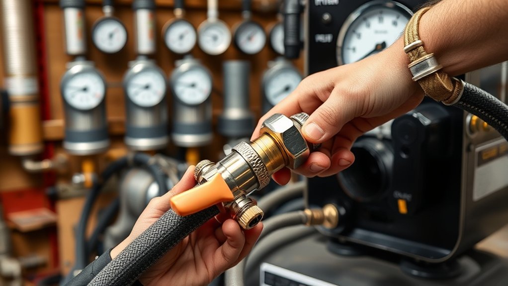
Choose a hose that can carry the required airflow without excessive pressure loss. A long, narrow, kinked, or internally damaged hose can make the cutter sputter even when the compressor gauge looks normal.
Check the pressure rating of the hose first. The hose and every fitting must be rated above the maximum pressure that can reach them from the compressor. Do not use a hose rated only for the cutter’s normal working pressure when the compressor can supply a higher pressure upstream of the regulator.
Then check the internal diameter and length. A short hose with a modest flow requirement may work with a smaller internal diameter. Higher airflow or a longer run may need a larger hose to reduce pressure drop. Use the cutter manual, hose manufacturer’s flow data, and approved adapters rather than selecting the hose by inlet-port size alone.
Durable rubber, hybrid polymer, and suitable PVC air hoses can work when they have the correct pressure, temperature, abrasion, and shop-use ratings. Keep the hose away from sparks, sharp sheet-metal edges, hot slag, standing water, and vehicle traffic.
A current 45-amp plasma cutter can require 6.7 SCFM at 90 PSI. The correct hose must carry the machine’s required airflow, not merely fit its inlet connection.
Use full-flow couplers and fittings that match the hose and the cutter’s required airflow. A small or restrictive quick-connect fitting can become the narrowest point in the system.
If the cutter uses tapered pipe threads, apply only the thread sealant permitted by the equipment manufacturer. Keep tape or sealant away from the first thread so loose material cannot enter the air path. Do not put thread tape on quick-connect sealing surfaces, flared fittings, compression seats, or connections that seal with an O-ring.
Products Worth Considering

EXTREMELY FLEXIBLE - All weather flexibility (-40° to 140°F)

Construction Applications: Supplies compressed air to pneumatic tools and inflation accessories

【Includes 1 Cutter】For no air leakage, the cross section of the 3 8 air line must be smooth and flat, no gap, uneven, and the tube cannot be oval. Our air tubing come with a tube cutter to make cutting more convenient and easier!
Step 2: Connecting the Air Compressor to the Plasma Cutter
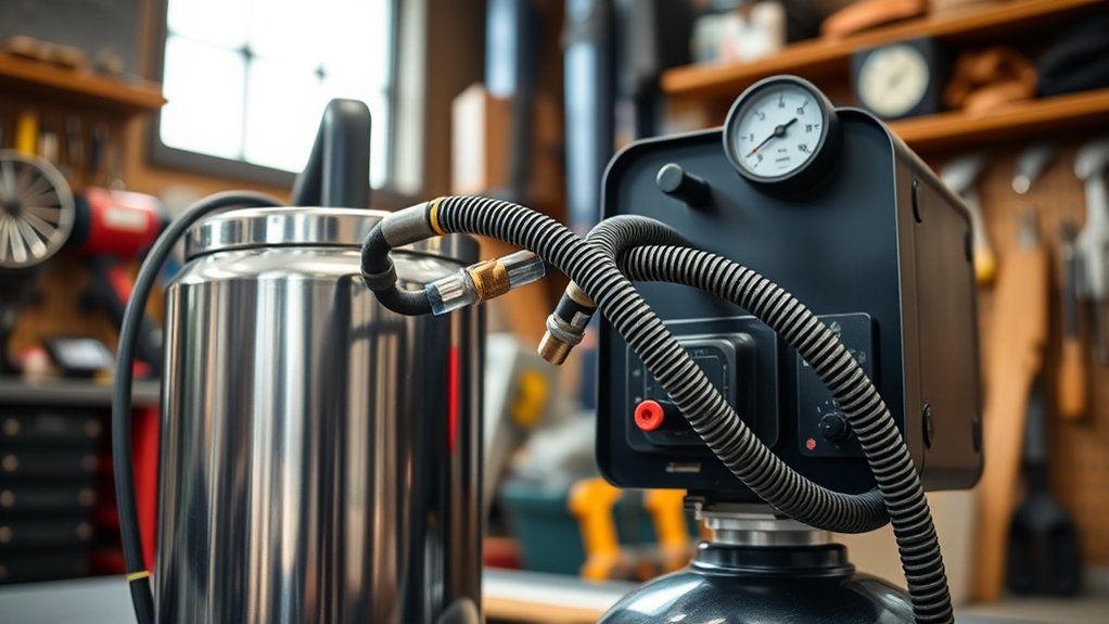
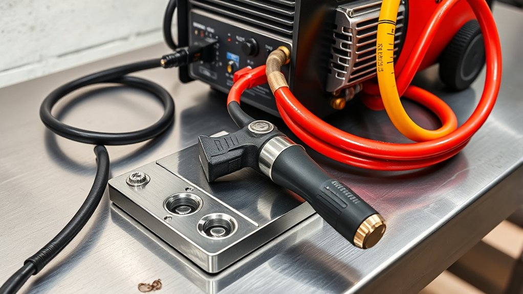
Connect the system only after confirming that the cutter is switched off and unplugged. Close the compressor’s outlet valve, if fitted, and release pressure from the hose before changing threaded components or couplers.
- Inspect the components: Check the hose, couplers, filter bowls, regulator, and inlet fitting for cracks, corrosion, damaged threads, loose seals, or contamination.
- Confirm pressure ratings: Make sure every component can safely handle the compressor’s maximum available pressure.
- Connect the compressor end: Push the quick-connect plug fully into the coupler, or start a threaded fitting by hand to avoid cross-threading.
- Install the treatment components: Connect the moisture separator, filters, and regulator in the approved direction shown by their airflow arrows.
- Connect the cutter end: Attach the final hose or filter assembly to the plasma cutter’s air inlet.
- Support the hose: Route it where sparks, slag, hot metal, doors, wheels, and foot traffic cannot damage it.
- Pressurize the line slowly: Open the compressor outlet gradually and watch for sudden movement, leaking bowls, or loose fittings.
- Check for leaks: Apply a compatible leak-detection solution to threaded joints and couplers. Repair bubbling connections before cutting.
A small leak can waste compressor capacity and reduce the pressure available during a cut. Static pressure may still look normal because the compressor can refill the line while the torch is off.
Pro Tip: Perform the leak test before setting final working pressure. A system that loses pressure through a fitting, damaged hose, or filter bowl cannot be adjusted accurately.
Step 3: Installing a Moisture Filter or Regulator
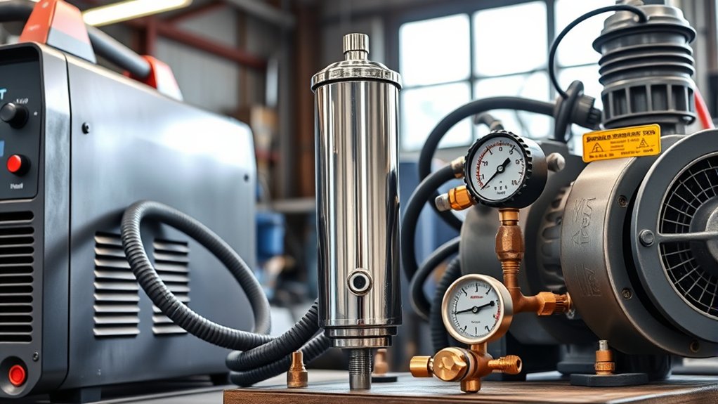
Plasma cutters generally need clean, dry, oil-free air. Water, oil mist, rust, and particles can reduce cut quality, shorten consumable life, and contaminate the torch or internal air system.
Start by draining the compressor tank according to its manual. Water collects as compressed air cools, especially in humid conditions. An automatic tank drain can help when the compressor is used frequently.
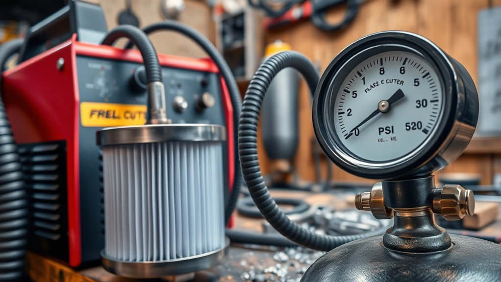
A practical air-treatment arrangement may include:
- Tank drainage: Removes liquid water stored in the compressor receiver.
- Downstream moisture separator: Collects water that condenses after the compressed air cools in the hose or pipe.
- Particulate filter: Captures rust, dirt, and other solid contamination.
- Coalescing or oil-removal filter: Helps remove oil aerosols when the compressor or shop-air system may introduce oil.
- Pressure regulator: Controls the pressure supplied to the plasma cutter.
- Final point-of-use filter: Protects the cutter from contamination that develops farther along the air line.
Hypertherm’s air-filter guidance notes that a second filter can be placed at least 20 feet downstream of the compressor, where additional moisture may have condensed. It also recommends considering a refrigerated dryer or desiccant system in very humid or high-use environments.
Install filters in their marked airflow direction and within their pressure and flow ratings. Mount bowls upright unless their instructions specifically permit another position. Drain manual filter bowls before the liquid reaches the marked limit.
Warning: Do not install an airline lubricator upstream of a plasma cutter that requires oil-free air. Oil intended for pneumatic tools can contaminate the torch and consumables.
Pro Tip: Drain the compressor tank before a long cutting session and again after the job. In humid weather, inspect the point-of-use filter more often because water can collect quickly.
Step 4: Setting the Air Compressor to the Recommended PSI
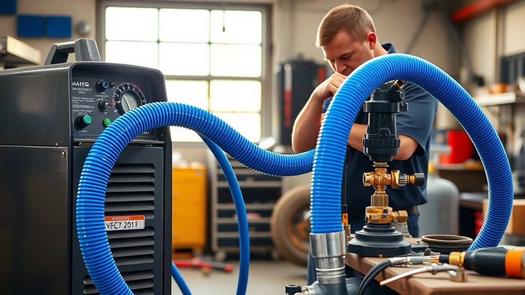
Set pressure from the plasma cutter manual, not from a general online range. The correct value may be listed as inlet pressure, supply pressure, operating pressure, or gas pressure.
The compressor tank gauge and the regulated outlet gauge show different information. Tank pressure tells you the stored pressure inside the receiver. The regulated gauge shows the pressure sent toward the cutter. The value that matters most is the pressure available at the cutter while air is flowing.
Optimal PSI Range
There is no single optimal PSI range for every plasma cutter. The correct combination depends on the machine, torch, consumables, amperage, airflow requirement, hose restrictions, and cutting mode.
Use these rules instead of experimenting with arbitrary pressure settings:
- Find the approved inlet pressure and airflow in the cutter manual or data plate.
- Make sure the compressor can deliver the required CFM or SCFM at that PSI.
- Keep the supply within the machine’s minimum and maximum inlet limits.
- Set working pressure with air flowing through the machine.
- Do not raise pressure above the specified range to compensate for a leak, dirty filter, restrictive coupler, or undersized hose.
Note: A compressor may display high tank pressure while the pressure at the cutter falls during airflow. This usually points to inadequate compressor output, a regulator restriction, pressure loss, or depleted stored air.
Adjusting Pressure Settings
- Start with the cutter off: Confirm that all connections are secure and the regulator is turned down before pressurizing a new setup.
- Turn on the compressor: Let it reach its normal cut-out pressure.
- Power the cutter: Follow the startup sequence in the machine manual.
- Activate air-test mode: Use the machine’s gas-test or air-flow function when available. If the manual provides another approved method, follow it.
- Adjust the regulator: Turn it slowly until the flowing-pressure reading matches the specified value.
- Release air-test mode: Confirm that the pressure remains stable when air flow starts and stops.
- Make a test cut: Use clean scrap metal of similar type and thickness to the workpiece.
If pressure drops below specification while air flows, do not simply increase the static regulator setting. Check the compressor’s output, tank recovery, hose length, hose diameter, filters, couplers, leaks, and other tools connected to the same air supply.
Ensuring Optimal Cutting Performance
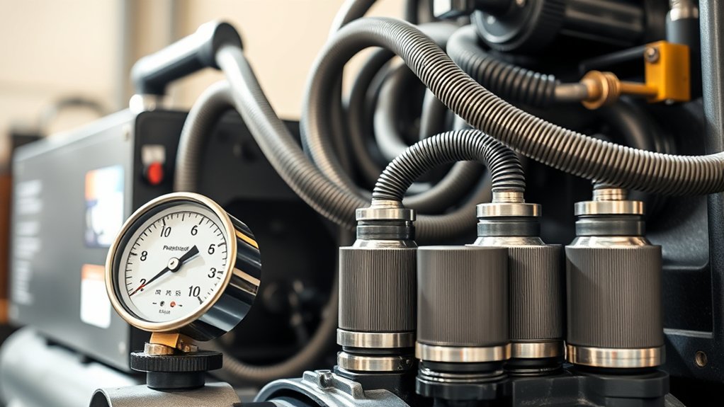
Clean cuts depend on air supply, consumable condition, electrical input, work-clamp contact, torch position, and travel speed. Check the complete setup before blaming one pressure setting.
- Air pressure and flow: Keep both within the cutter’s specified range while air is moving.
- Consumables: Use the correct tip, electrode, shield, and retaining components for the torch and amperage.
- Air filters: Drain bowls and replace filter elements according to their condition and service schedule.
- Hoses and fittings: Remove kinks, leaks, crushed sections, and restrictive adapters.
- Work clamp: Attach it to clean, bare metal on the workpiece or cutting table, as directed by the machine manufacturer.
- Travel speed: Move steadily so the arc penetrates the full thickness and sparks exit through the bottom of the cut.
- Electrical input: Use the correct supply voltage, plug, breaker, and extension-cord arrangement specified by the cutter manufacturer.
The Miller handheld plasma-cutter guide recommends inspecting consumables, checking air pressure, cleaning the clamp area, and placing the work clamp close to the cut before starting.
First Test-Cut Checklist
- The compressor tank and filter bowls have been drained.
- The compressor can maintain the required airflow at the specified pressure.
- No joint bubbles during the leak test.
- The regulator was set while air was flowing.
- The hose is not kinked, crushed, hot, or lying in the spark path.
- The filter and regulator arrows point toward the cutter.
- The consumables are correct, clean, and properly installed.
- The work clamp contacts clean metal.
- The amperage suits the material and consumables.
- The test piece is clean, electrically conductive, and safe to cut.
Make a short test cut on scrap before touching the real workpiece. Inspect the edge for incomplete penetration, excessive dross, a wide or irregular kerf, and bevel. Then correct one variable at a time.
Safety Precautions and Best Practices
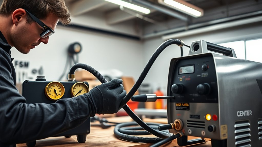
Plasma cutting creates intense light, ultraviolet and infrared radiation, hot sparks, molten metal, fumes, noise, compressed-air hazards, and electrical hazards. Protect yourself and anyone nearby before you power the machine.
OSHA’s welding and cutting guidance identifies hazards that include burns, eye damage, electrical shock, ultraviolet radiation, and metal fumes.
Protective Gear Essentials
- Welding helmet or cutting shield: Use a lens shade suitable for the cutter’s amperage and the visibility of the arc.
- Safety glasses: Wear impact-rated glasses with side protection under the helmet to help stop flying slag and debris.
- Flame-resistant clothing: Cover exposed skin with dry, undamaged clothing that will not melt or ignite easily.
- Cutting gloves: Use dry gloves that protect your hands without reducing torch control.
- Hearing protection: Use suitable protection when noise levels or the cutting environment require it.
- Foot protection: Wear sturdy footwear that keeps hot slag from entering around the ankle or tongue.
OSHA’s eye-and-face protection table lists minimum shade 8 for light plasma arc cutting below 300 amps when the actual arc is clearly visible. Follow your cutter manual and workplace rules, and select a darker shade when needed without going below the applicable minimum.
Warning: Never watch a plasma arc with unfiltered safety glasses alone. Protect helpers and bystanders with suitable screens, barriers, or correctly shaded eye protection.
Proper Equipment Handling
Check all air connections before cutting. Replace a hose that is cracked, blistered, burned, abraded to reinforcement, or damaged at a coupling. Do not repair a pressure hose with ordinary tape.
Inspect tips, electrodes, shields, and retaining parts before each job. Worn consumables can create an unstable arc, angled cut, excessive dross, enlarged kerf, or failed start.
Keep the cutter and compressor dry. Do not touch energized equipment with wet gloves or work in standing water. Use the electrical supply, grounding arrangement, and extension-cord limits in the equipment manuals.
| Task | Equipment Check | Why It Matters |
|---|---|---|
| Wear PPE | Helmet, safety glasses, gloves, clothing, hearing and foot protection | Protects against radiant energy, sparks, noise, and hot metal |
| Secure connections | Rated, leak-free hoses, filters, and fittings | Maintains airflow and reduces pressure-related hazards |
| Treat the air | Tank drain, separator, filter, and dryer when needed | Keeps water, oil, and particles out of the cutter |
| Replace consumables | Tip, electrode, shield, and retaining parts | Supports stable arc control and cleaner cuts |
| Check working pressure | Manual-based setting measured during airflow | Reveals pressure drop hidden by a static gauge reading |
| Bleed the hose | Outlet closed and trapped pressure released | Prevents fittings or hoses from moving violently during disconnection |
Safe Work Environment
- Clear combustibles: Move paper, cardboard, fuel, solvents, sawdust, aerosols, and other flammable items away from the spark path.
- Control hidden fire paths: Check the opposite side of walls, floors, panels, and workpieces where sparks or molten metal may travel.
- Ventilate the area: Use suitable local exhaust or ventilation so fumes move away from your breathing zone.
- Identify coatings: Do not cut painted, plated, galvanized, stainless, or otherwise coated material until you understand and control its fume hazards.
- Avoid sealed or contaminated containers: Do not cut a tank, drum, pipe, or container that may hold pressure, fuel, vapor, or hazardous residue unless it has been made safe under an approved procedure.
- Protect nearby people: Use noncombustible screens and keep bystanders out of the direct spark and arc path.
- Control trip hazards: Route hoses, torch leads, and power cables away from walkways and sharp edges.
- Keep fire equipment ready: Have an appropriate extinguisher available and follow workplace hot-work requirements.
Common Mistakes to Avoid
- Choosing by PSI alone: A compressor can reach the required pressure yet fail to supply enough airflow.
- Choosing by tank size alone: A large tank delays pressure loss but does not increase continuous pump output.
- Using an underrated hose: Every air component must handle the maximum pressure that can reach it.
- Using a long, narrow hose: Excessive length and small internal diameter can cause pressure loss during flow.
- Using restrictive couplers: A small quick-connect can limit an otherwise adequate hose.
- Skipping moisture or oil control: Contaminated air can damage consumables and reduce cut quality.
- Using an airline lubricator: Oil intended for pneumatic tools should not feed a cutter requiring oil-free air.
- Setting pressure without airflow: Static pressure can look correct while working pressure falls too low.
- Increasing pressure to hide another problem: Leaks, dirty filters, and undersized hoses must be corrected directly.
- Ignoring compressor duty cycle: Continuous operation can overheat a compressor that was designed for intermittent use.
- Disconnecting a pressurized line: Close the supply and bleed trapped pressure before removing a fitting.
- Ignoring the manual: Pressure, airflow, consumables, electrical supply, and cutting procedures vary by model.
Note: A compressor that runs continuously, loses tank pressure, or forces frequent cutting pauses may be undersized, restricted, leaking, or operating beyond its rated duty cycle.
Plasma Cutter Air-Supply Troubleshooting
| Symptom | Likely Causes | What to Check |
|---|---|---|
| Torch sputters or arc stops | Low working pressure, wet air, worn consumables, loose work clamp | Flowing-pressure reading, filter bowl, tank drain, consumables, clamp contact |
| Pressure drops when air-test starts | Insufficient compressor CFM, restrictive regulator, narrow hose, small coupler, leak | Compressor output at required PSI, hose dimensions, fittings, filter rating, leak test |
| Compressor runs without stopping | Air demand exceeds output, major leak, dirty intake, duty-cycle limit | Required SCFM, compressor rating, leaks, maintenance, operating schedule |
| Water appears in filter or torch line | Full tank drain, humid air, hot compressor discharge, inadequate separation | Drain tank, inspect separators, add downstream treatment or a suitable dryer |
| Consumables wear unusually fast | Wet or oily air, incorrect pressure, bad piercing technique, wrong parts | Air quality, flowing pressure, consumable compatibility, torch procedure |
| Heavy dross or incomplete cut | Low airflow, wrong speed, low amperage, worn tip, material too thick | Air supply, travel speed, amperage, consumables, rated cutting capacity |
| Air leaks after disconnection | Damaged coupler, debris, worn seal, valve problem | Depressurize, inspect the coupler and seals, and replace damaged components |
Frequently Asked Questions
Can I Use a Plasma Cutter Without an Air Compressor?
A standard air-plasma cutter normally needs compressed air from an external compressor or another approved gas source. Some compact plasma cutters have a built-in compressor. Check the machine specifications before buying or connecting equipment.
What Size Air Compressor Do I Need for a Plasma Cutter?
Choose a compressor that can deliver at least the cutter’s required CFM or SCFM at the specified PSI. Also check compressor duty cycle, hose pressure loss, and whether other air tools will run at the same time. Tank size provides temporary storage but does not replace adequate pump output.
How Many CFM Does a Plasma Cutter Need?
The requirement varies by machine and cutting mode. Read the manual or specification plate and match the listed airflow at the listed pressure. As one example, the Hypertherm Powermax45 SYNC specifies 6.7 SCFM at 90 PSI, but that value should not be applied to a different cutter.
Does a Bigger Compressor Tank Make a Plasma Cutter Work Better?
A larger tank gives you more stored air and can reduce rapid pressure changes during short cuts. It does not increase the compressor pump’s continuous CFM. Once stored air is depleted, the pump still has to keep up with the cutter’s demand.
Can I Use an Oil-Lubricated Air Compressor?
You may be able to use an oil-lubricated compressor when the air-treatment system removes liquid water, particles, and oil contamination to the standard required by the plasma cutter. Do not install an airline lubricator before a cutter that requires oil-free air.
Can I Use a 1/4-Inch Air Hose for a Plasma Cutter?
It depends on the required airflow, hose length, couplers, and pressure loss. A short 1/4-inch hose may work for some low-flow cutters, while a longer run or higher-flow machine may need a larger internal diameter. Confirm that the hose delivers the required airflow at the cutter during operation.
Where Should I Put the Moisture Filter and Regulator?
Drain the compressor tank first, then use moisture separation after the air has had an opportunity to cool. Install suitable filtration and the regulator in the approved flow direction, with final point-of-use filtration near the cutter when needed. Follow each component manufacturer’s mounting and sequence instructions.
What Is the Lifespan of a Plasma Cutter Nozzle?
Nozzle life depends on air quality, amperage, piercing technique, cutting time, material, and correct torch setup. Replace the nozzle when its orifice becomes enlarged or irregular, or when you see unstable arcs, heavy dross, excessive bevel, or an uneven kerf.
How Do I Maintain My Plasma Cutter for Longevity?
Keep the unit clean and dry, drain the air system, service filters, inspect consumables, and protect the torch lead from heat and sharp edges. Check hoses, fittings, power connections, and the work clamp before each job. Follow the maintenance intervals in the cutter manual.
Are There Portable Options for Plasma Cutters?
Yes. Portable plasma cutters are available for small shops, field work, vehicle repair, and light fabrication. Some include a built-in compressor, while others still need an external air source. Check input power, cutting capacity, airflow, weight, and duty cycle before choosing one.
What Materials Can a Plasma Cutter Cut Through?
A plasma cutter can cut electrically conductive metals such as carbon steel, stainless steel, aluminum, copper, and brass. Maximum thickness and cut quality depend on machine output, material type, air or gas supply, consumables, electrical input, and travel speed.
Why Does My Plasma Cutter Sputter While Cutting?
Sputtering commonly comes from low working pressure, inadequate airflow, water or oil in the air, worn consumables, a poor work-clamp connection, unstable input power, or incorrect torch setup. Check pressure while air flows, drain the compressor, inspect filters and consumables, and clean the clamp area.
Safety Disclaimer
Safety Disclaimer: This article is for informational purposes only and does not replace your plasma cutter manual, compressor manual, filter and regulator instructions, workplace safety rules, or professional training. Follow the manufacturer’s requirements and get qualified help if you are unsure about electricity, compressed air, fumes, coatings, pressure vessels, fire hazards, or safe cutting procedures.
Sources
- Hypertherm Powermax45 SYNC specifications — example of model-specific clean-air, airflow, and pressure requirements
- Hypertherm air-plasma filter guidance — moisture control, tank drainage, downstream filtration, and dryer recommendations
- Miller handheld plasma-cutter guide — air supply, consumables, work-clamp preparation, and pre-cut checks
- Atlas Copco compressor-sizing guide — airflow, pressure, application demand, storage, and duty-cycle considerations
- OSHA welding and cutting hazards — fumes, radiation, burns, electrical hazards, and PPE
- OSHA 29 CFR 1910.133 — eye and face protection and minimum plasma-cutting lens shades
Conclusion
A plasma cutter works best when the compressor supplies enough airflow at the machine’s specified working pressure. Start with the manual, compare the cutter’s CFM or SCFM requirement with the compressor’s delivered output, and make sure the hose, couplers, filters, and regulator can carry that flow safely.
Drain the compressor, keep oil and moisture out of the cutter, set pressure while air is flowing, and repair leaks or restrictions instead of masking them with a higher regulator setting. Make a short test cut on scrap before starting your real project.
With a correctly sized compressor, dry air, stable working pressure, good consumables, and proper safety controls, you can get smoother cuts while protecting the torch, compressor, and plasma cutter.