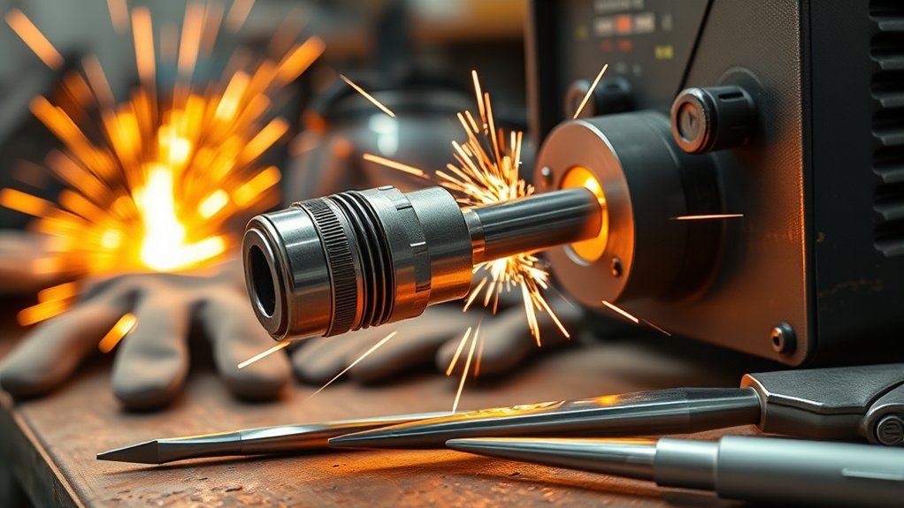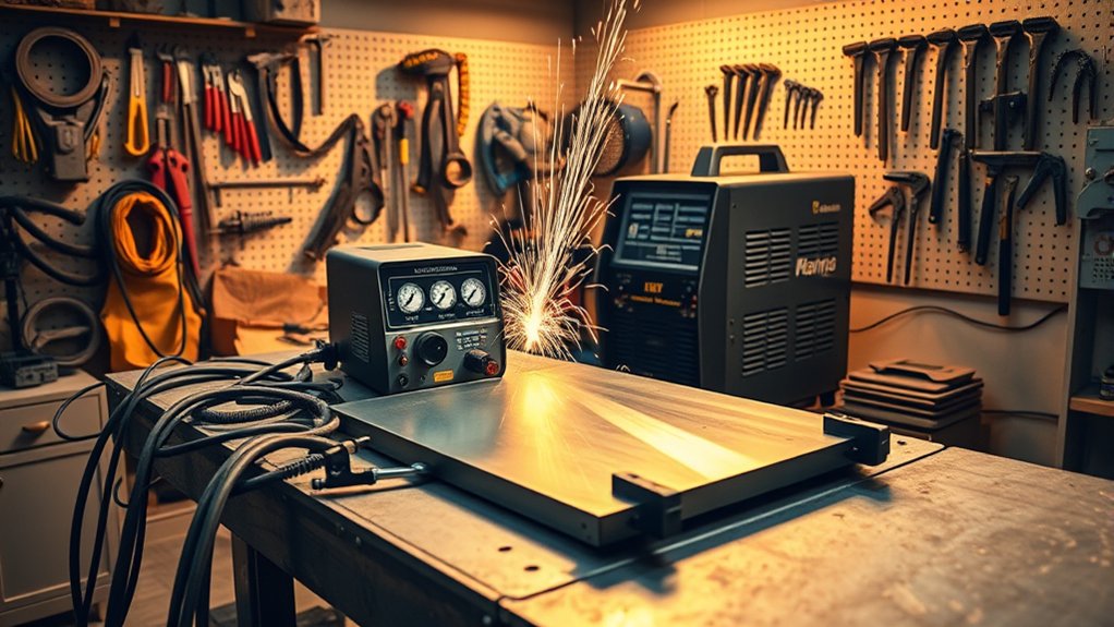
Setting up a plasma cutter is straightforward when you match the machine to the correct power source, supply clean and dry air, install the right consumables, and make solid metal-to-metal contact with the work clamp. The exact voltage, airflow, amperage, and torch setup vary by model, so keep your operator manual beside you during the first setup.
Quick Answer
To set up a plasma cutter, confirm the input power and circuit, connect a clean, dry air supply that meets both PSI and CFM requirements, install the correct consumables, attach the work clamp to clean metal, choose the cut mode and amperage from the manual, then make a test cut on matching scrap.
Key Takeaways
- Match the outlet, circuit, phase, and generator capacity to the data plate and operator manual.
- Check air pressure and airflow. Static PSI alone does not show whether the compressor can keep up.
- Use clean, dry, oil-free air and drain moisture before it reaches the cutter.
- Attach the work clamp to bare metal on the part that will remain after the cut.
- Use the cut chart for consumables, amperage, mode, torch height, and travel speed.
- Test on scrap that matches the project metal and thickness before making the final cut.
At a Glance
| Time Required | About 15 to 30 minutes for a first setup and test cut |
| Difficulty | Beginner, provided the electrical supply is already installed correctly |
| Tools Needed | Plasma cutter, approved air source, air filter or dryer, correct fittings, PPE, scrap metal, and the operator manual |
| Cost | No extra cost if you already have the correct power, air supply, fittings, PPE, and scrap; electrical work or air treatment adds cost |
Warning: Plasma cutting creates intense light, hot sparks, fumes, noise, and electric-shock hazards. Work in a dry, ventilated area, remove combustible materials, wear proper PPE, and never cut a sealed, pressurized, fuel-contaminated, or unknown container.
Before You Set Up the Plasma Cutter
Read the operator manual and the data plate before connecting anything. A plasma cutter may look ready to plug in, but voltage, phase, input current, breaker size, generator capacity, air pressure, and airflow can differ widely between models.
Confirm that the material is electrically conductive. Air plasma cutters can cut metals such as mild steel, stainless steel, aluminum, copper, and brass, but they do not cut wood, glass, plastic, or other nonconductive materials.
Prepare a Safe Work Area
- Move paper, sawdust, fuel, solvents, aerosols, and other combustibles away from the spark path.
- Check below and behind the workpiece because sparks and molten metal can travel through gaps.
- Use general ventilation or local exhaust so fumes move away from your breathing zone.
- Do not cut in rain, standing water, or damp clothing.
- Identify coatings before cutting. Galvanized, painted, plated, or contaminated metal may release hazardous fumes.
- Support the workpiece so the cut-off section cannot fall on a cable, hose, foot, or flammable surface.
Wear the Right PPE
Use safety glasses with side protection under a properly shaded face shield or helmet, flame-resistant gloves and clothing, closed leather footwear, and hearing protection. OSHA lists a minimum shade 8 for visible plasma arc cutting below 300 amps. Follow the higher requirement when your machine manual or workplace rules call for one.
Connecting the Power Supply
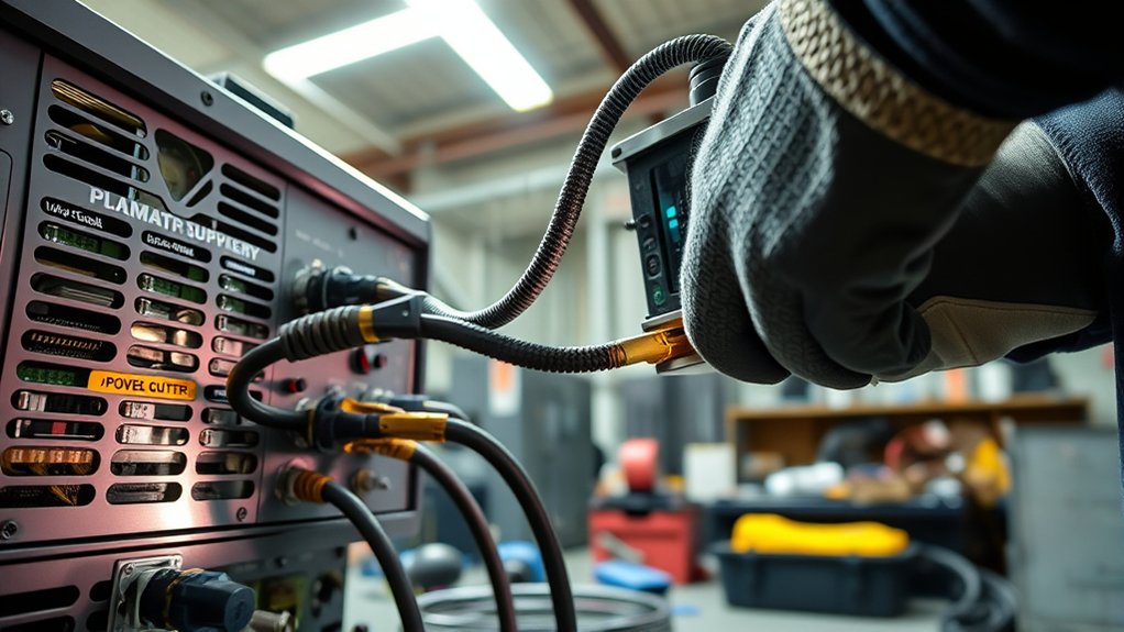
Keep the plasma cutter switched off while you inspect the cord, plug, receptacle, torch lead, and work lead. Check for cuts, loose pins, heat damage, or damaged insulation.
Match the machine’s input voltage and phase to the power source. Do not assume that a plug fits just because the outlet shape looks correct. The data plate and manual tell you the permitted voltage range, input current, breaker or fuse requirements, and generator size.
Many plasma cutters have a factory-installed power cord. Some models require a plug or hardwired connection. Have a qualified electrician complete that work and install the required protective earth connection. The work clamp does not replace the equipment’s protective earth ground.
After the torch, work lead, air supply, and consumables are connected, switch the machine on. Confirm the normal power indicator appears and no fault light or fault code remains active.
Note: A long or undersized extension cord can cause voltage drop and poor performance. Use an extension cord only when the manufacturer allows it, and follow the conductor-size and length limits in the manual.
Attaching the Air Source
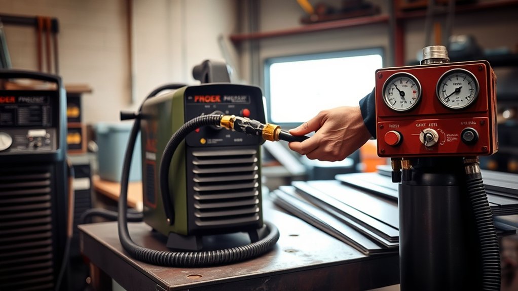
Connect the cutter to the air or gas source approved for your model. Most handheld air plasma cutters need clean, dry, oil-free compressed air. A machine with a built-in compressor may not need an external air line.
Check two numbers in the manual: inlet pressure and required airflow. A small tank can show adequate PSI while idle but lose pressure quickly because it cannot supply enough cubic feet per minute during a cut.
Products Worth Considering
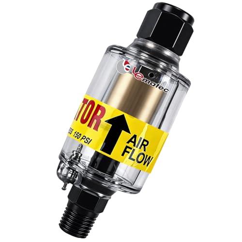
Moisture Protection: 1-micron reusable element removes air compressor oil and water from compressed air systems; essential for precise spray painting and plasma cutting

【Industrial Performance】The air drying system features two rugged 3/4“ NPT air ports and 1/4” NPT gauge ports to handle high-pressure environments (up to 240 PSI) for a variety of industrial applications. Note: To prevent air leakage, please wrap the sealing tape around the threads appropriately before connecting the screws.

3/8" NPT Piggyback Air Filter/Regulator Combo
Connecting the Air Line
Install the fitting specified by the manufacturer, then connect the hose fully to the cutter’s inlet. Keep dirt, metal chips, thread-sealant fragments, and moisture out of the air path.
Do not apply sealing tape or compound blindly. Some machines specify a particular thread sealant and torque value, while quick-connect surfaces normally seal without tape. Follow the fitting instructions in the manual.
Ensuring Proper Pressure and Airflow
Set and check the pressure while air is flowing, not only while the system sits idle. The compressor must maintain the required pressure and flow for the length of your cut.
For example, Hypertherm lists clean, dry, oil-free air at 7.5 scfm and 85 psi for cutting with the current Powermax85 SYNC. Other plasma cutters use different values, so a generic 80 to 100 PSI setting is not reliable.
If the pressure falls during a cut, look for an undersized compressor, a restricted filter, a small hose, a leak, or excessive hose length.
Securing Air Fittings and Removing Moisture
Tighten fittings to the manufacturer’s specification and check for leaks with the system pressurized. Drain the compressor tank and install suitable filtration or drying equipment when moisture or oil reaches the line.
Dirty or wet air can shorten consumable life, damage the torch, and cause unstable cutting. Replace clogged filters and worn hoses before they restrict flow.
Pro Tip: Watch the pressure gauge during a long test cut. If pressure drops only when the torch is firing, the problem is usually available airflow or a restriction rather than the static regulator setting.
Connecting the Work Clamp
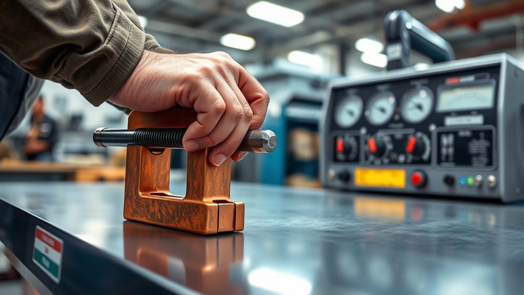
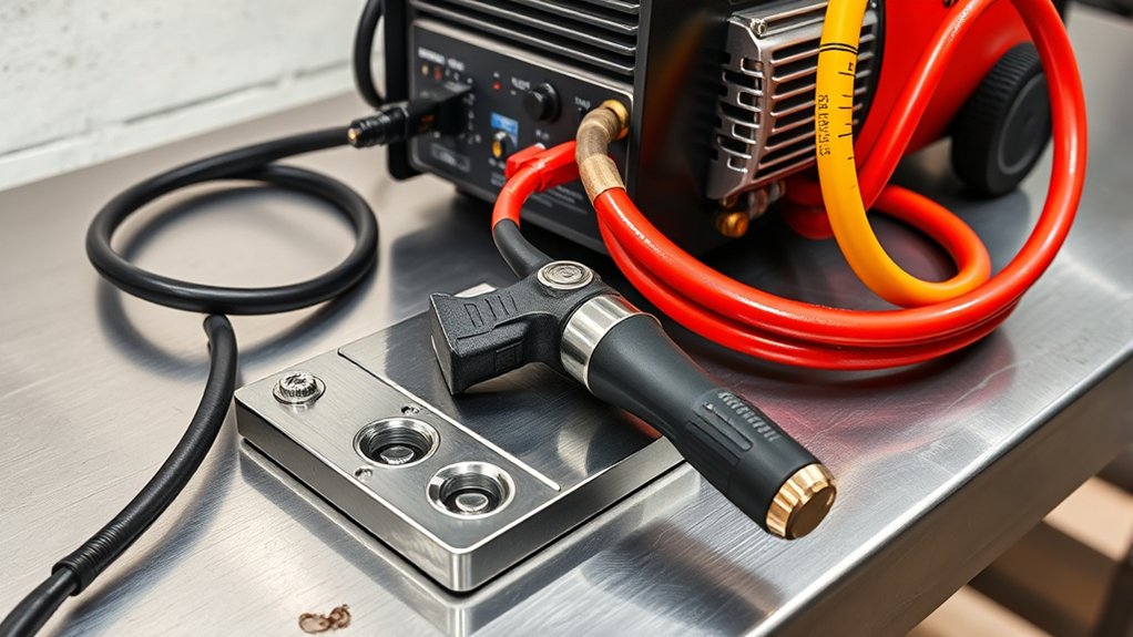
Attach the work clamp to clean, bare metal on the workpiece whenever possible. Put it close to the cut without placing it where sparks, molten metal, or the falling offcut can damage the clamp or cable.
The work lead completes the cutting circuit. It is separate from the protective earth conductor that grounds the machine chassis for electrical safety.
Products Worth Considering

9 1/2-Inch long with 2-1/4 wide jaw opening

300A / 500A / 800A Arc Welding Manual Welder Earth Ground Cable Copper Grip Clip Clamp Heavy Duty.

360° Rotating Device: This welding ground clamp adapter features a 360° rotating mechanism, eliminating cable entanglement issues when working with M10 aperture clamps for smoother and flexible welding
Ensuring Clean Metal-to-Metal Contact
Remove paint, rust, scale, oil, and heavy mill coating at the clamp point. Make sure the jaws grip firmly and the work cable connection is tight.
If you clamp to a metal cutting table, confirm the workpiece has reliable electrical contact with the table. Loose slats, heavy scale, or an isolated workpiece can interrupt the circuit.
Why the Work-Clamp Connection Matters
A weak connection can cause difficult arc transfer, intermittent cutting, excessive dross, or a fault condition. It can also encourage the arc to find an unintended path through bearings, chains, electronics, or other connected equipment.
Never attach the clamp to the section that will fall away after the cut. When that section separates, the cutting circuit may open before the cut finishes.
Troubleshooting Work-Clamp Problems
- Move the clamp directly to clean metal on the workpiece.
- Clean both clamp jaws and the contact area.
- Tighten the work-lead connection at the machine.
- Inspect the cable for broken strands, burns, or loose lugs.
- Check that the workpiece is not insulated from a cutting table by paint, scale, or debris.
Adjusting the Amperage
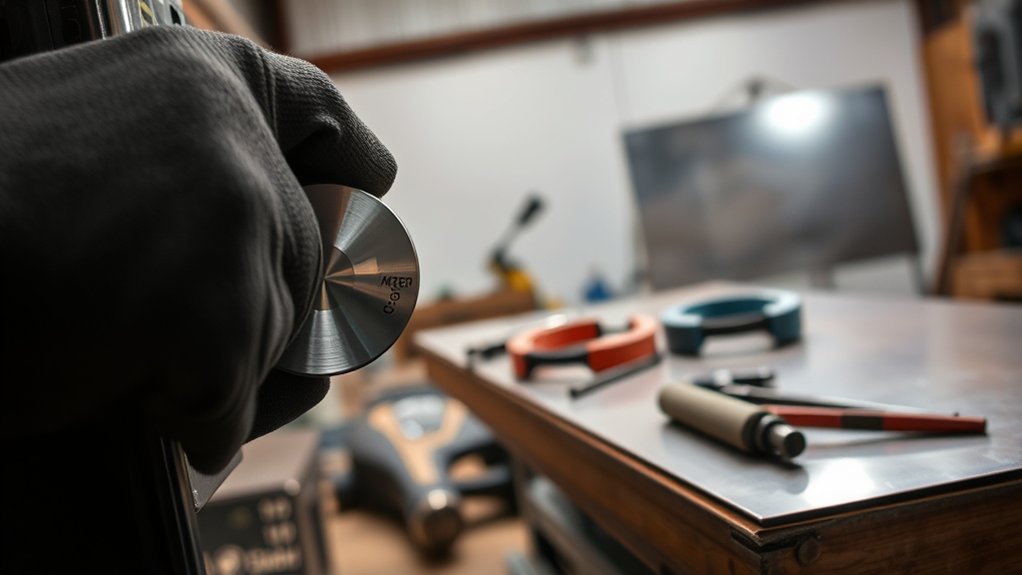
Choose the consumable or cartridge first, then set the current according to its rating and the cut chart. Do not set the machine only by material thickness or by turning the dial to maximum every time.
Current ranges differ by model. The current Powermax85 SYNC, for example, has a 25 to 85 amp output range, not 0 to 85 amps. Its SmartSYNC cartridge can set the operating mode and amperage automatically, while older systems require manual selection.
- Thin metal: Use the lower-current process listed in the cut chart when the installed consumable supports it. This can improve control and reduce heat input.
- Thicker metal: Use the recommended higher-current consumable and setting. Do not exceed the nozzle or cartridge rating.
- Poor severance: Confirm current, travel speed, air supply, consumable condition, and rated cut capacity before raising amperage.
Excess current can shorten nozzle life. Low current with the wrong consumable can produce a weak, wandering cut. The manual’s cut chart gives you a safer starting point than a universal amperage rule.
Selecting the Cutting Mode
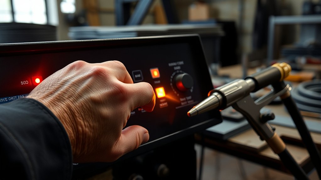
Select the mode that matches the job and installed consumables. Common modes include:
- Continuous plate cutting: For solid sheet and plate.
- Expanded-metal or restart mode: For grating, mesh, and interrupted cuts that repeatedly break and restart the arc.
- Gouging: For removing metal rather than cutting through it.
- Mechanized cutting: For compatible CNC tables or automated equipment.
Control layouts are not universal. The “second icon down” describes certain older Powermax65 and Powermax85 panels, but it should not be treated as a rule for every plasma cutter. Powermax SYNC systems can identify a cartridge and set the process automatically, although you may still adjust current or select an interrupted-cut mode when needed.
Preparing the Torch and Performing a Test Cut
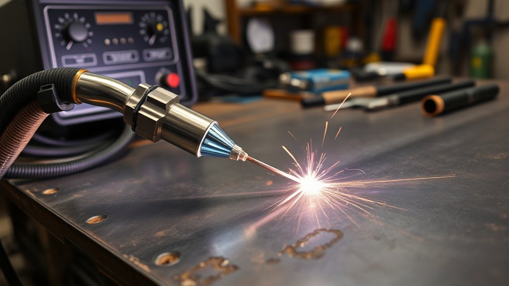
Switch off the cutter and use the torch lock or disable switch before handling consumables. Let post-flow stop, then inspect the shield, retaining cap, nozzle, electrode, swirl ring, or cartridge for cracks, burns, blocked holes, an enlarged nozzle opening, or a deeply worn electrode pit.
Install the exact parts listed for the torch and process. Seat them cleanly and tighten the retaining cap only as directed. Never use ordinary grease inside the torch. If an O-ring needs lubricant, use only the approved product and a very light film.
Choose the correct torch arrangement:
- Drag cutting: Use a drag shield or drag-rated cartridge that allows contact with the workpiece.
- Standoff cutting: Hold the torch at the distance listed in the cut chart. Do not drag an exposed nozzle on the metal.
Make the First Test Cut
- Use scrap with the same metal type and thickness as the project.
- Mark a straight cut line and support both sides of the scrap.
- Attach the work clamp to clean metal on the section that will remain.
- Set the consumable, mode, amperage, and air supply from the manual.
- Hold the torch square to the surface and start from the edge when possible.
- Pause until the arc fully penetrates, then move at a steady speed.
- Watch the sparks under the plate. They should pass through the metal and trail slightly behind the torch.
- Inspect the edge, bevel, dross, kerf, and whether the cut fully separated.
Edge Starting Versus Piercing
An edge start is easier on consumables because molten metal can exit without blowing back toward the torch. Use an edge start for your first test whenever the part allows it.
When you must pierce away from an edge, follow the torch-height and thickness limits in the manual. Thick material may require a rolling pierce that starts with the torch tilted so molten metal sprays away from the nozzle. Do not pierce material thicker than the system’s rated pierce capacity.
A clean test cut should fully separate the metal, show limited removable dross, and produce a steady spark stream through the bottom of the plate.
Common Plasma Cutter Mistakes to Avoid
- Using pressure without checking flow: The gauge may show enough PSI while the compressor still lacks the required CFM.
- Cutting with wet or oily air: Contamination can damage the torch and shorten consumable life.
- Clamping over paint or rust: Poor contact makes arc transfer unreliable.
- Using the wrong consumables: A mismatched nozzle, shield, electrode, cartridge, or mode reduces cut quality and part life.
- Running the wrong current: Match amperage to the installed consumable and cut chart.
- Moving too fast: The arc may not fully penetrate, and sparks may spray back or upward.
- Moving too slowly: The kerf widens, heat input rises, and low-speed dross builds under the cut.
- Using the wrong standoff: Torch height affects bevel, dross, arc stability, and consumable wear.
- Piercing too close: Molten blowback can damage the nozzle or shield.
- Ignoring post-flow: Let the cooling air finish before switching off the air supply or removing consumables.
Troubleshooting Poor Cut Quality
| Symptom | Likely Checks |
| Arc will not transfer | Clean and move the work clamp, inspect the work cable, check consumable installation, and confirm the material is conductive. |
| Cut does not go through | Slow down, verify amperage and air flow, inspect consumables, reduce standoff if the manual calls for it, and confirm the metal is within rated capacity. |
| Heavy dross | Adjust travel speed, check torch height, verify current and consumables, and confirm clean, dry airflow. |
| Large bevel or angled edge | Hold the torch square, inspect the nozzle opening, correct travel direction and height, and keep a steady speed. |
| Consumables wear quickly | Check air contamination, current rating, excessive piercing, incorrect assembly, low pierce height, and air pressure outside the specified range. |
| Arc starts and stops | Look for falling air pressure, a loose work connection, worn consumables, overheating, or a displayed fault code. |
Routine Maintenance After Setup
Do not rely on a universal three- or six-month service interval. Maintenance depends on the model, arc-on time, number of starts, air quality, dust, duty cycle, and operating environment.
- Before each session: Inspect the cord, torch lead, work lead, clamp, consumables, hoses, fittings, and air filter.
- During use: Watch for pressure drop, fault codes, changing cut quality, and unusual heat or noise.
- After use: Let post-flow finish, switch off the machine, drain compressor moisture, and store the torch where the lead will not kink.
- At the manual’s interval: Clean or replace filters, inspect fans and vents, tighten approved connections, and complete the listed service checks.
Judge consumables by wear and cut quality rather than a fixed number of hours. Track starts or arc-on time if you want a realistic life estimate for your own material and process.
Frequently Asked Questions
What safety gear should you wear when operating a plasma cutter?
Wear safety glasses with side protection, a properly shaded face shield or helmet, flame-resistant gloves and clothing, closed leather footwear, and hearing protection. OSHA lists minimum shade 8 for visible plasma arc cutting below 300 amps. Use ventilation or local exhaust, and follow any higher shade or respiratory protection requirement in the machine manual or workplace assessment.
What air pressure should a plasma cutter use?
Use the inlet pressure and airflow listed for your exact model. Both PSI and CFM matter. For example, the current Powermax85 SYNC specifies 7.5 scfm at 85 psi for cutting, while other machines use different values. Check pressure while air is flowing.
How often should a plasma cutter be serviced?
Inspect cables, hoses, the work clamp, consumables, and air quality before each session. Drain moisture and service filters as conditions require. Use the manufacturer’s schedule for deeper maintenance because the interval changes with arc-on time, starts, dust, duty cycle, and the model.
Can you use a plasma cutter outdoors in wet conditions?
No. Do not use a plasma cutter in rain, standing water, or damp clothing. Keep the machine, torch, work area, gloves, and footwear dry. Move the job to a dry location with safe ventilation and fire control.
How long do plasma cutter consumables last?
There is no reliable universal hour range. Life changes with amperage, starts, piercing technique, air quality, torch height, material, and consumable design. Inspect the nozzle opening, electrode pit, shield, and cut quality, and track starts or arc-on time for your own setup.
How can you troubleshoot poor cut quality?
Start with the work-clamp connection, consumable condition and assembly, air pressure and flow, amperage, torch height, and travel speed. Also confirm that the metal is within the cutter’s rated capacity and check any fault code shown on the panel.
Can you plasma cut painted or galvanized metal?
A plasma arc can cut conductive coated metal, but the coating can create hazardous fumes and interfere with the work-clamp connection. Identify the coating, remove it at the clamp point, use suitable ventilation or local exhaust, and follow the safety requirements for zinc, lead, cadmium, chromium, paint, or other contaminants.
Wrapping Up
A safe plasma cutter setup depends on four things: correct electrical input, enough clean and dry airflow, a reliable work-clamp connection, and settings that match the consumables and metal. Verify each item in the manual, inspect the torch, and make a test cut on matching scrap. When the arc stays steady, sparks pass through the plate, and the edge needs little cleanup, you are ready to cut the project.
Sources
- Hypertherm Powermax85 SYNC specifications — output range, power options, cut capacity, and inlet air requirements
- Hypertherm Powermax SYNC setup and operation — current setup sequence, automatic settings, torch lock, and PPE guidance
- Hypertherm guide to plasma cutting — consumable setup, work-clamp placement, edge starting, and piercing
- Hypertherm common plasma cutting mistakes — consumable wear, amperage, gas quality, torch height, and travel speed
- OSHA 29 CFR 1910.133 — eye and face protection and filter-shade guidance
- OSHA 29 CFR 1910.252 — fire prevention, ventilation, and hazardous coating precautions for cutting work