
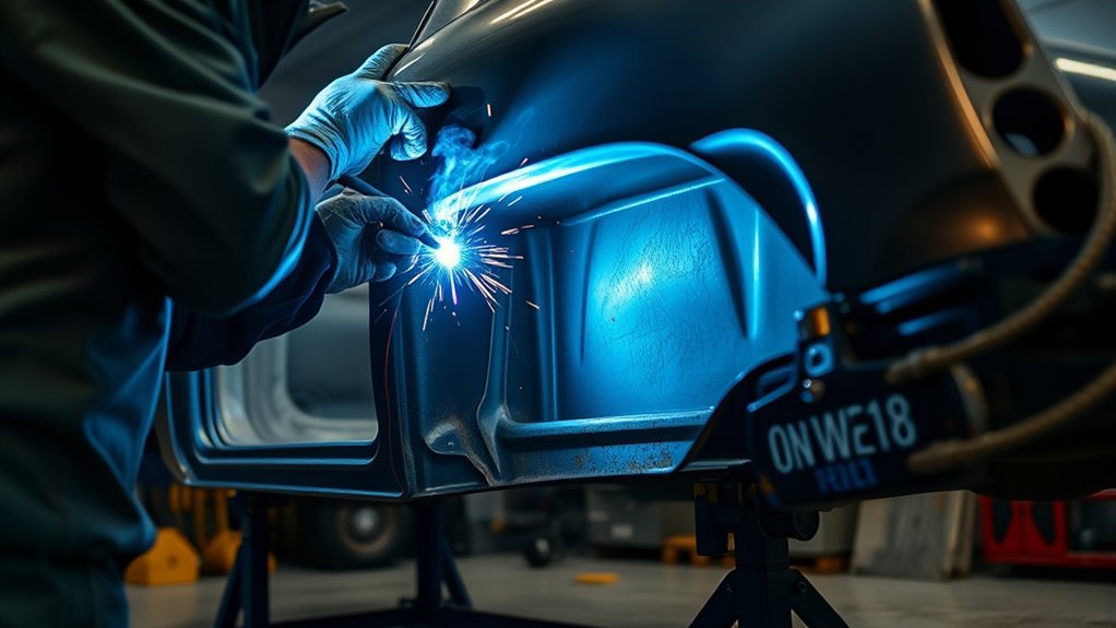
An inner rocker panel is often part of a vehicle’s side structure, so this job is more than a cosmetic rust patch. A safe repair starts with the vehicle-specific body repair manual, correct body support and measurements, complete removal of weakened metal, and the exact joining and corrosion-protection methods required for that model.
Quick Answer
To weld an inner rocker panel, first confirm that the vehicle maker allows the planned replacement or sectioning method. Depower the vehicle, support and measure the body, remove all weak metal, test-fit the panel, and verify door gaps. Use only the specified weld, adhesive, and joint pattern, then inspect, prime, seal, coat, and cavity-wax the repair.
Key Takeaways
- Check the vehicle-specific body repair manual before cutting. Some inner rocker reinforcements must be replaced as complete assemblies and must not be sectioned.
- Do not weld over rust, paint, seam sealer, undercoating, grease, or thin weakened steel.
- Measure and support the body before removing a structural rocker, then verify the door opening throughout fit-up and welding.
- Do not assume MIG plug welds are always correct. The approved method may include squeeze-type resistance spot welding, GMA/MIG welding, MIG brazing, adhesive, or a specified combination.
- After welding, restore primer, seam sealer, exterior coatings, cavity protection, drain paths, foams, and baffles as required by the repair procedure.
At a Glance
| Time Required | Usually at least a full working day for straightforward access; multi-layer corrosion, structural measuring, refinishing, and cure times can extend the job considerably |
| Difficulty | Advanced collision repair; professional structural repair is the safer choice when the inner reinforcement, pillars, floor, seat-belt anchorage, jack point, or crash structure is affected |
| Tools Needed | OEM repair information, measuring tools, approved body support or rack equipment, the specified welding or bonding system, grinder, spot-weld cutter, clamps, PPE, ventilation, and fire-protection equipment |
| Cost | Varies widely with the vehicle, panel assembly, hidden corrosion, required welding equipment, adhesives, corrosion materials, and refinishing; structural shop labor can cost far more than the panel and consumables |
Warning: An inner rocker or rocker reinforcement may be a structural, crash-management component. Do not section, heat-straighten, pull, weld, or substitute material unless the vehicle maker permits that exact operation. Follow the body repair manual whenever the rocker connects to the floor, pillars, seat-belt anchorage, jack point, battery enclosure, or side-impact structure.
Confirm the OEM Repair Procedure Before Cutting
Identify the exact year, make, model, body style, and powertrain before planning the repair. Then obtain the vehicle-specific body repair manual and check the body construction diagram, panel replacement procedure, sectioning limits, weld locations, adhesive requirements, corrosion-protection steps, and any calibration or inspection requirements.
This check is essential because a replacement panel being available does not automatically mean you may cut it anywhere you choose. Some vehicle makers allow an outer rocker to be sectioned at named locations but require the inner reinforcement to be replaced at factory seams. For example, current Ford and Lincoln rocker reinforcement guidance summarized by I-CAR describes full reinforcement replacement where no sectioning cut lines are provided.
- Confirm whether the damaged part is an outer cosmetic panel, inner rocker, reinforcement, floor-side member, or multi-layer assembly.
- Identify the metal type and strength classification. Do not assume every layer is mild steel.
- Confirm whether heat straightening, sectioning, butt welding, lap welding, plug welding, spot welding, MIG brazing, rivets, or adhesive are allowed.
- Record required weld count, weld locations, plug-hole size, flange preparation, adhesive bead location, and joint overlap only from the approved procedure.
- Check whether destructive test coupons, corrosion-restoration products, foam replacement, scans, or calibrations are required.
If no vehicle-specific procedure is available, do not invent a structural repair method. Use an approved OEM information source or send the vehicle to a qualified collision-repair facility.
Products Worth Considering

Step-by-step procedures written from a complete teardown and rebuild, giving you the confidence to tackle repairs at any skill level.

Professional Dent Removal: VEVOR Stud Welder Dent Puller offers a fast and efficient solution for removing dents from steel car body panels, all while providing precise dent pulling and controlled force for a professional-grade dent repair every time.

COMPREHENSIVE KIT - Includes bumping, pick, and reverse curve hammers plus four specialized dollies, providing professional-grade tools for both major collision repair and precision dent removal on vehicles
Support, Measure, and Depower the Vehicle
Measure the door opening, rocker height, pillar locations, and other body reference points before cutting. Compare the measurements with the body repair manual and, when useful, with the undamaged side. Photograph the gaps and mark reference points that will remain after the damaged panel is removed.
Support the vehicle exactly as the repair procedure requires. Depending on the design, this may mean approved lift points, a body rack, fixtures, or a specified suspension-loaded condition. Do not assume that simply placing the vehicle level on jack stands will prevent movement. If the door opening can lose shape, install temporary bracing only where the repair procedure or accepted structural-repair plan permits it.
Depower the vehicle before welding or cutting. Follow the OEM sequence for the 12-volt battery, restraint system, retained power, capacitors, and electronic modules. I-CAR’s GMA welding precautions for vehicle electronics include disconnecting and isolating battery cables, keeping the work return clamp close to the weld, and protecting electronic components.
Hybrid and electric vehicles need additional controls. Identify high-voltage cables, battery enclosures, cooling lines, and isolation procedures before work begins. Use the vehicle maker’s instructions and the NHTSA emergency response guide library as supporting safety information. High-voltage disabling or battery removal must be performed by a qualified person when required.
Note: Disconnecting only the negative battery terminal is not a universal depowering procedure. Some vehicles require waiting periods, both battery cables to be isolated, service disconnects to be removed, modules to be protected, or the high-voltage battery to be de-energized or removed.
Clean and Prep the Rocker Area
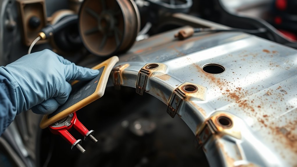
Start by stripping the rocker area down to clean metal. Use a grinder, wire wheel, or abrasive disc to remove rust, paint, seam sealer, undercoating, and debris until you can see the condition of every layer that will remain.
Inspect the surrounding sheet metal for cracks, thinning, holes, previous patchwork, distorted flanges, torn spot welds, and hidden corrosion. Cut out or replace compromised sections according to the approved repair plan so you do not attach a new panel to weak metal.
Clean-looking edges do not prove that a rocker is sound. Inspect every exposed layer, reinforcement, flange, and adjoining floor or pillar before the replacement panel goes in.
Degrease before final grinding, then clean again as the product maker directs. Oil, wax, road grime, old cavity coatings, and solvent trapped in seams can contaminate welds, produce fumes, or create porosity. Allow approved cleaners to evaporate fully before hot work.
Prepare only the areas required for the selected joint. Preserve factory coatings outside the weld zone when the OEM procedure allows. On overlapping flanges, apply weld-through primer, weldable sealer, adhesive, or bare-metal preparation exactly as specified. Weld-through primer rules differ by vehicle maker and welding process, and some procedures require it to be removed from the direct GMA weld zone to reduce porosity.
Keep the work zone dry, supported, ventilated, and well lit. Remove nearby carpet, trim panels, plastic clips, foam, wiring, sound deadener, and insulation when possible. When an item cannot be removed, protect it with metal guards or a proper welding blanket and watch both sides of the panel.
Tools and Materials You’ll Need
Gather the repair information, measuring equipment, tools, and coatings before opening the rocker. Stopping midway because a clamp, adhesive, primer, or cavity wand is missing can leave the body unsupported and bare metal exposed.
- Vehicle-specific body repair manual, body dimensions, and material identification information
- Replacement inner rocker, reinforcement, or complete service assembly specified for the vehicle
- OEM-approved joining equipment, which may include GMA/MIG, squeeze-type resistance spot welding, MIG brazing, rivet bonding, or structural adhesive equipment
- Welder setup charts, test coupons, and scrap steel that matches the approved material and stack thickness as closely as practical
- Cut-off wheel, grinder, flap disc, wire brush, body saw, seam splitter, and spot-weld cutter as needed
- Drill and approved plug-weld tooling when the procedure calls for GMA plug welds
- Vice grips, panel clamps, locking pliers, magnets, and OEM-acceptable temporary fasteners
- Body measuring tools, tram gauge, straightedge, gap gauges, and any required body rack or fixtures
- Wheel chocks, approved stands or lifting equipment, and temporary bracing materials when permitted
- Welding helmet, gloves, hearing protection, safety glasses, protective clothing, and appropriate respiratory protection
- Local exhaust ventilation, fire extinguisher, welding blanket, spark shields, and a trained fire watcher when required
- Specified weld-through primer or weldable sealer, epoxy primer, seam sealer, adhesives, paint, undercoating, cavity wax, plugs, foam, and baffles
Pro Tip: Make test welds before touching the vehicle. Reproduce the same metal stack, coating preparation, hole size, access angle, and welding position, then peel or destructively test the coupon to confirm fusion. A bead that looks smooth on top can still have poor attachment underneath.
Products Worth Considering

【Applications Range】: The inner tie rod removal tool features a 3/8" plug that fits most common car chassis rocker arm inner tie rod sizes and all standard tie rods with smooth cylindrical ends. Widely used in automotive repair applications, it meets a wide range of chassis adjustment needs.

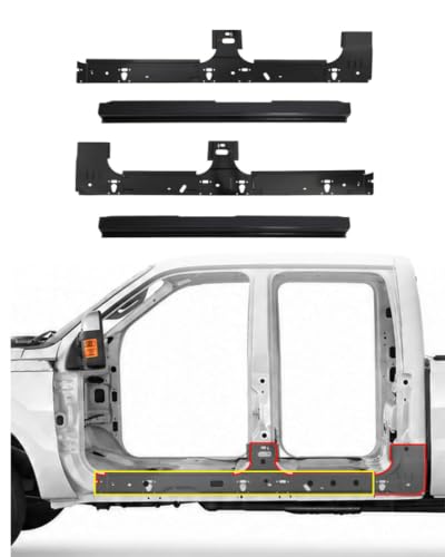
3D Laser Scanned for OEM-Level Fit: 4pcs rocker panels are designed to fit for 1999-2017 Ford Super Duty F250, F350 crew cab, which can provide a reliable solution to get your truck back on road with perfect fitment.
Remove the Damaged Inner Rocker
Lift or fixture the vehicle using the approved support points and verify the body measurements before cutting. Chock the wheels and keep the structure stable so the shell does not shift while the rocker is open.
Before you cut, remove or protect anything that could burn, melt, short, or release hazardous fumes. Check both sides and the inside of the rocker for fuel lines, brake lines, wiring harnesses, drain tubes, battery components, carpet, insulation, structural foam, and plastic trim.
Use a cut-off wheel, body saw, spot-weld cutter, or other approved separation tool to remove the damaged inner rocker in controlled sections. Keep blades and cutters shallow so you do not nick the floor, pillar bases, outer rocker, reinforcements, or undamaged mating flanges.
If the original rocker was attached with spot welds, locate and separate them carefully. Preserve a mating flange only when it is undamaged, has adequate thickness, and the repair procedure permits reuse. Do not enlarge holes or tear the flange with an air chisel simply to speed removal.
Mark factory reference points before the panel comes off, including rocker ends, pillar edges, door-opening measurements, bracket locations, drain paths, foam positions, and weld patterns. Keep removed sections available until the new panel is fitted so you can compare construction details.
After the damaged section comes free, inspect the exposed assembly. Look for rust trails between layers, cracked seams, torn weld nuggets, distorted flanges, collision damage, and holes in the floor edge. Repair or replace every weak adjoining part before installing the new rocker.
Finish by vacuuming debris, cleaning corrosion, dressing weld nuggets without thinning the flange, and preparing each joint according to the repair procedure. The replacement can fit correctly only when the old damage is fully removed and the remaining structure is straight.
Straighten the Bent Rocker
Inspect the rocker opening closely and identify every bend, crease, twist, and collapsed flange that must be corrected before fitting the replacement section. Confirm first that the material and component are repairable. Some high- or ultra-high-strength reinforcements must be replaced rather than heated or pulled.
Use a body rack, controlled hydraulic equipment, hammer and dolly, or body spoon only where the OEM procedure allows. Work slowly and make small corrections so you do not stretch the metal, damage coatings beyond the repair area, or move the door opening past specification.
Check the measurements often. The rocker must align with the floor edge, pillars, outer rocker, brackets, and lower door opening before you weld or bond the replacement.
Assess Rocker Damage
Before you cut more metal or clamp the new panel in place, map the damage. Mark high spots, low spots, collapsed sections, torn welds, and pinch points that could block a clean fit.
- Measure the door opening and body reference points before and after panel removal.
- Compare the damaged side with OEM dimensions and with the opposite side only when the opposite side is known to be straight.
- Check whether rust or collision damage has reached the floor pan, pillar base, reinforcement, jack point, seat-belt anchorage, or outer rocker.
- Identify stretched metal, buckles, cracks, and heat-sensitive steel that may change the repair plan.
If the door opening has moved, correct it before attaching the replacement panel. Welding a rocker into a twisted opening can lock in poor door fit and place unwanted stress in the body structure.
Push Panel Into Place
With the damage mapped, use controlled pressure to return repairable areas to specification. Check the body line, lower door gap, floor flange, pillar ends, brackets, and reference measurements after each adjustment.
| Check | Action |
|---|---|
| Body dimensions | Compare with the OEM measuring points before fit-up |
| Door latch | Test closure before final attachment when the door can remain installed safely |
| Door gap | Measure the top, rear, front, and lower gaps |
| Pressure | Apply gradually and remeasure after each correction |
| Clamp | Use clamps or fixtures that hold the flange without distorting it |
| Attach | Add temporary tacks only when the approved procedure uses GMA welding |
Temporary clamps, fixtures, and permitted fasteners let you fine-tune fit without committing too early. Once the panel sits true, lock the position using the method specified for that repair, then recheck dimensions, latch operation, and gaps.
Test-Fit the New Inner Rocker
Set the replacement inner rocker or reinforcement in place and secure it with approved clamps or fixtures. Compare it with the surrounding bodywork and verify that the door opening, floor flange, pillar joints, and brackets remain within specification.
Inspect every edge for gaps, twist, overlap errors, damaged E-coat, or high spots. The panel should sit against the mating flanges without heavy force. If you must force it into place, find and correct the cause before permanent attachment.
Keep the door installed during test-fitting when access, repair instructions, and fire safety allow. Close it gently and check the latch, striker, lower gap, body line, and weatherstrip contact. When the door must be removed, use measurements, fixtures, and repeated temporary installation as needed to verify the opening.
- A close, even fit supports consistent welds and adhesive bond-line control.
- Accurate alignment reduces grinding, filler, and rework.
- Correct door gaps help prevent latch, wind-noise, water-leak, and weatherstrip problems.
- Correct bracket, drain, and access-hole alignment prevents assembly problems later.
If the procedure calls for GMA plug welds, make holes only where specified and use the stated diameter and spacing. Deburr the holes and confirm that each one sits over sound underlying metal. If the procedure calls for squeeze-type resistance spot welds, adhesive, MIG brazing, or another process, prepare the flange for that process instead.
Note: Do not apply ordinary seam sealer, paint, or undercoating in a weld or adhesive bond zone before attachment. Use only the weld-through primer, weldable sealer, adhesive, or bare-metal preparation named by the OEM and product instructions.
Choose the Correct Joint and Weld Method
Match the replacement method to the body repair manual, not to the equipment you happen to own. Modern rocker assemblies may combine several steel strengths, multiple layers, adhesives, spot welds, laser welds, MIG-brazed joints, and corrosion coatings.
| Method | Use It Only When | Main Control |
|---|---|---|
| Squeeze-type resistance spot welding | The OEM procedure calls for it and the electrodes can reach the joint | Correct machine capability, electrode access, test welds, and coating preparation |
| GMA/MIG plug welding | It is an approved substitute for factory spot welds at the named locations | Specified hole size, clean underlying metal, fusion around the hole, and controlled heat |
| GMA/MIG seam or stitch welding | The OEM procedure permits that joint design and weld length | Joint gap, sequence, penetration, heat-affected zone, and distortion |
| MIG brazing | The vehicle maker specifies it for the material and joint | Correct wire, shielding gas, equipment, joint preparation, and lower heat input |
| Weld bonding or rivet bonding | The repair procedure names the adhesive, fastener, and process | Surface preparation, bead location, open time, squeeze-out, cure, and weld compatibility |
Never replace an approved joint with a continuous bead simply because it looks stronger. Extra heat or a different joint can change the heat-affected zone, stiffness, load path, and corrosion protection.
Clamp and Tack Weld the Panel
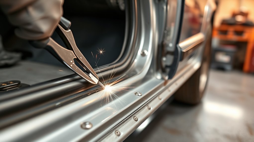
Clamp the replacement panel tightly enough to maintain flange contact without crushing or distorting it. Check the body dimensions, door latch, and door gaps before attachment, then adjust the panel until the opening remains within specification.
When the approved repair uses GMA welding, place small positioning tacks at selected reference points. Start where the panel location is most critical, then work outward so it cannot creep. Do not add positioning tacks in an adhesive-only zone or where the OEM process does not permit them.
Secure Panel With Clamps
Use vice grips, butt-weld clamps, flange clamps, fixtures, or permitted temporary fasteners that match the joint design and leave access for the joining process.
- Stable clamping prevents unwanted movement.
- Full flange contact supports consistent spot, plug, or adhesive-bonded joints.
- Accurate positioning protects door gaps, body dimensions, and bracket alignment.
- Clamps must not hide gaps, flatten a designed step, or squeeze all adhesive out of a bonded joint.
When GMA positioning tacks are allowed, space them to hold alignment while limiting heat. Remove only the clamps that block access, and keep the rest in place until the weld or adhesive sequence is stable.
Check Door Alignment
With the inner rocker clamped and, when permitted, lightly tacked, close the door and verify alignment. The door should swing freely, latch cleanly, seal evenly, and avoid contact with the rocker.
| Check | Good Result |
|---|---|
| Hinge swing | Smooth movement with no contact or sudden drop |
| Latch engagement | Normal engagement without lifting, slamming, or striker drag |
| Gap uniformity | Within OEM specification and visually consistent around the opening |
| Panel position | Stable after clamping or approved positioning tacks |
| Body measurement | Reference points remain within the body repair manual specification |
If the door drags, sits proud, or has an uneven lower gap, stop and adjust the panel before adding permanent welds, adhesive, or fasteners. Small corrections are easier now than after the repair is fully attached.
Tack Weld In Spots
When GMA tacks are part of the approved plan, place small tacks at separated locations and avoid building heat in one area. Keep the work return clamp on clean metal close to the weld site, following OEM electrical-protection instructions.
Check the door latch and body measurements after each group of tacks. If the panel shifts, correct it before the tacks become too numerous or too large to release cleanly.
- Move around the panel instead of completing one area from start to finish.
- Allow hot spots to cool naturally before welding nearby.
- Do not cool structural welds with compressed air or water unless the vehicle maker permits it.
- Do not grind positioning tacks so thin that they crack while the panel is being handled.
Once the panel remains aligned, continue with the specified spot welds, plug welds, seam welds, brazed joints, adhesive, or combined process.
Check Door Latch Alignment
After the rocker is positioned, check latch alignment by closing the door gently and confirming that it shuts smoothly and securely without excessive force.
Open and close the door several times. Watch for binding, weak engagement, striker drag, a changing lower gap, or a door that sits too far in or out from the fender and quarter-panel surfaces.
Measure the gaps with a ruler, straightedge, taper gauge, or feeler gauge as appropriate. Compare them with the recorded pre-repair condition and OEM tolerances. Do not rely only on a visual check when the rocker is structural.
If the latch misses or the door sits proud, adjust the panel while it is still held by reversible clamps or limited positioning tacks. Correct the rocker or body opening first. Adjust the striker or hinges only when their prior condition and the OEM procedure show that adjustment is appropriate.
Repeat the test until the latch engages normally and the door sits correctly. Good fit at this stage helps prevent poor sealing, rattles, wind noise, water entry, and stress in the finished repair.
Finish Welding the Inner Rocker
Finish the attachment only after the panel is clamped, measured, and aligned. Follow the exact weld count, location, joint, adhesive, and sequence in the vehicle-specific procedure.
Use plug welds only where they are an approved replacement for factory spot welds. Use stitch, seam, or butt welds only where the procedure calls for them. Do not run a continuous bead across thin rocker metal unless that exact bead is specified.
Move around the repair in a planned sequence to control heat and shrinkage. Complete a short approved weld, move to a separated area, and allow the previous location to cool. Continue checking dimensions and door operation as the panel becomes fully attached.
- Use enough heat for fusion without enlarging the heat-affected zone unnecessarily.
- For plug welds, fuse to the underlying panel and tie the weld into the edge of the hole.
- For spot welds, confirm electrode access, machine settings, coating preparation, and test results.
- For weld-bonded joints, protect the adhesive bond line and follow the adhesive maker’s open time and cure requirements.
- Watch for panel movement, adhesive squeeze-out, burn-through, and coating fires after each work cycle.
Inspect every joint for fusion, pinholes, undercut, porosity, skipped edges, cracks, adhesive voids, or missing welds. Compare weld number and placement with the repair procedure. Repair defects before grinding, sealing, or coating.
Warning: Sparks and heat can travel through rocker cavities and ignite seam sealer, foam, dust, carpet, insulation, or undercoating. OSHA’s hot-work rule requires fire hazards to be removed or protected and, when a fire watch is required, kept for at least 30 minutes after welding or cutting. Inspect both sides and all cavities during and after the work.
Troubleshoot Common Welding Problems
| Problem | Likely Cause | Correction |
|---|---|---|
| Burn-through | Weak metal, poor fit, excess heat, or wrong settings | Stop, remove metal that is too thin to support the approved joint, improve fit, and retest settings on a coupon |
| Plug weld sits high but has weak fusion | Arc stayed on the top panel, hole was too small, or underlying metal was coated or dirty | Remove the defective weld, restore the approved hole and surface preparation, then direct the arc into the underlying panel before filling outward |
| Porosity | Contamination, trapped solvent, poor gas coverage, wind, or primer in the direct weld zone | Remove the porous weld, clean and dry the joint, correct gas delivery and shielding, and follow the OEM coating rule |
| Door gap changes during welding | Heat shrinkage, weak support, poor clamping, or body movement | Stop welding, remeasure the body, correct support and alignment, then revise the sequence before continuing |
| Repeated cracking | Wrong joint, unsupported panel, excessive grinding, contamination, or material that should not be repaired that way | Stop and recheck the OEM procedure, material identification, joint design, and adjoining damage before attempting another weld |
Grind and Clean the Welds
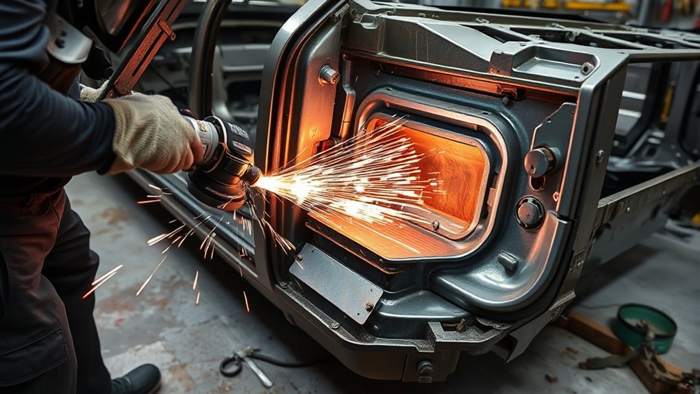
Grind only the welds that must be flush for fit, sealing, or refinishing. Use a flap disc, belt sander, or approved grinding tool with controlled passes. Keep the tool moving so you do not thin the surrounding metal, cut into a flange, or weaken a plug weld.
Remove spatter and residue with an appropriate abrasive or wire brush, then inspect each joint under good lighting. Check for consistent fusion, complete plug-weld tie-in, cracks, pinholes, porosity, undercut, missed welds, and heat damage.
If you find defects, remove and repair them before coating. Do not hide pinholes or weak welds under body filler, seam sealer, adhesive, or undercoating.
Wear eye protection, gloves, hearing protection, protective clothing, and suitable respiratory protection when grinding old paint, primer, undercoating, adhesive, or weld residue. Use extraction and keep abrasive dust out of the passenger compartment and rocker cavity.
Seal, Prime, and Protect the Repair
After the joints pass inspection, restore corrosion protection in the sequence required by the OEM and coating manufacturers. That sequence may differ by product, so do not assume every seam sealer goes directly on bare steel or every primer belongs under every adhesive.
Apply epoxy primer or another approved corrosion-resistant coating to prepared bare metal. Restore seam sealer over the same types of joints and in the same general locations as the factory application, while keeping drain paths and service holes open.
Refinish the exterior and underside with the specified paint system, chip protection, or undercoating. Inside the rocker, apply cavity wax or an approved internal corrosion material through access holes with the correct wand pattern. 3M’s collision-repair corrosion guidance specifically identifies rocker panels and other closed cavities as areas that need cavity protection after repair.
Replace any removed plugs, baffles, sound-deadening pads, or structural foam with the specified materials and at the specified stage. Do not use general household foam or sealer inside a structural cavity.
Make sure all rocker drain holes remain open. Blocking a drain can trap water and road salt inside the repaired cavity and restart corrosion.
Make Final Door Adjustments
Check the door gaps along the top, bottom, front, and rear edges after the vehicle is returned to the support or ride condition specified for final measurement. Open and close the door several times before completing trim installation.
Set the latch and striker only when adjustment is necessary and permitted. The door should close normally, remain flush with adjacent panels, and avoid binding or rattle. If it still drags, check hinge wear, body dimensions, panel position, and weld shrinkage before masking the problem with striker adjustment.
- The door should close without lifting or slamming.
- The weatherstrip should compress evenly.
- The lower gap and body line should remain within specification.
- The sill trim, weatherstrip retainers, and interior panels should fit without force.
Once the door and body measurements are correct, tighten hardware to the specified torque where applicable and complete the remaining coating, cavity-protection, and reassembly steps.
Final Inspection Checklist
Before you call the repair finished, inspect the rocker from inside, outside, underneath, and through available access holes.
- The correct vehicle-specific repair procedure was followed and any prohibited sectioning was avoided.
- All rusted, cracked, stretched, or thin metal was removed or repaired as permitted.
- Body dimensions and door gaps meet the repair information.
- Weld count, location, joint type, adhesives, and fasteners match the approved method.
- Plug welds, spot welds, seam welds, brazed joints, and bonded seams pass visual and required test checks.
- No pinholes, cracks, porosity, missed welds, loose adhesive, or unsupported edges remain.
- Primer, seam sealer, paint, chip protection, undercoating, and cavity wax are restored where required.
- Drain holes, access holes, plugs, foams, and baffles are correctly restored.
- No wiring, fuel lines, brake lines, high-voltage parts, trim, glass, carpet, or insulation was heat damaged.
- The 12-volt and high-voltage systems were restored through the OEM procedure.
- Required scans, calibrations, warning-light checks, water-leak checks, and road checks are complete.
- The work area and hidden cavities pass the final fire-watch inspection.
Frequently Asked Questions
Are rocker panels welded?
Many rocker assemblies use spot welds, plug welds, seam welds, laser welds, brazed joints, structural adhesive, or a combination. The correct replacement method depends on the vehicle’s body construction and repair manual.
What gauge steel should I use for an inner rocker panel?
There is no universal rocker-panel gauge. Use the correct OEM service part or material that matches the original thickness, strength grade, coating, and construction. A generic 18- or 20-gauge patch is not an acceptable substitute for a high-strength reinforcement unless the vehicle maker permits it.
What type of welder is best for rocker panels?
Use the process required by the vehicle-specific procedure. GMA/MIG is common for some plug and seam welds, but other repairs require squeeze-type resistance spot welding, MIG brazing, weld bonding, rivet bonding, or a combination. The best machine is the one capable of meeting the OEM specification and passing test welds.
Can I section an inner rocker reinforcement?
Only when the vehicle maker provides a sectioning procedure or clearly permits partial replacement at a named location. Many inner reinforcements must be replaced as complete assemblies or at factory seams because an improvised cut can reduce structural performance.
Can I repair a rocker panel without replacing it?
A limited outer-panel patch may be possible when the OEM allows it and the surrounding metal is sound. If corrosion reaches the inner rocker, reinforcement, floor edge, pillar base, jack point, seat-belt anchorage, or another structural area, replacement under an approved structural procedure is usually the safer repair.
Do I need to disconnect the battery before welding?
Yes, but follow the vehicle maker’s complete depowering procedure rather than using one generic battery step. The procedure may include both battery cables, a waiting period, restraint-system precautions, module protection, and high-voltage isolation or battery removal on hybrid and electric vehicles.
Do I need seam sealer after welding an inner rocker?
Usually, yes. After the joints pass inspection, restore the OEM corrosion-protection system with compatible primer, seam sealer, exterior coatings, and cavity wax. Follow the product sequence and keep drain holes open.
Conclusion
A sound inner rocker repair begins with the vehicle-specific procedure, not with a generic weld pattern. Confirm whether sectioning is allowed, identify the materials and joint methods, support and measure the body, depower the vehicle, and remove every weakened layer. During fit-up and attachment, keep checking body dimensions and door operation. After inspection, restore every corrosion barrier, drain path, foam, and cavity coating. When the rocker is part of the crash structure or the correct repair information and equipment are unavailable, a qualified collision-repair shop is the safer choice.
Sources
- OSHA 29 CFR 1910.252, General Requirements for Welding, Cutting, and Brazing supports hot-work fire prevention, combustible-material control, ventilation, and fire-watch guidance.
- I-CAR: Ford/Lincoln Rocker Panel Reinforcement Sectioning supports checking vehicle-specific procedures and avoiding unapproved reinforcement sectioning.
- I-CAR: Protecting Electronic Parts During GMA Welding supports battery isolation, work-clamp placement, and vehicle-electronics precautions.
- I-CAR: FCA/Stellantis Weld-Through Primer Guidelines shows that primer use and direct weld-zone preparation depend on the OEM and joining process.
- 3M Collision Repair Corrosion Protection Resources supports restoring cavity protection inside rocker panels and other closed body sections.
- NHTSA Emergency Response Guides provides vehicle-specific supporting information for electric, hybrid, plug-in hybrid, and fuel-cell vehicle hazards.




