
A 7/8-inch arbor hole is a common plain center hole used on angle grinder cutting, grinding, flap, and diamond discs. On a compatible conventional grinder, the hole slides over the threaded spindle and centers on the raised shoulder of the backing flange. A 7/8-inch hole alone does not prove that a disc is safe for your grinder; the wheel diameter, thickness, type, guard, flanges, material rating, and maximum RPM must also match.
Quick Answer
A 7/8-inch arbor hole is a common unthreaded disc opening, usually labeled 22.23 mm. On a compatible grinder, it centers on the backing flange rather than threading onto the spindle. Confirm the exact grinder model, wheel diameter, guard, flange set, thickness, material rating, and RPM before mounting the disc.
Key Takeaways
- A 7/8-inch plain-hole disc does not thread onto a 5/8-11 spindle; it normally centers on a raised shoulder on the backing flange.
- The metric equivalent is about 22.23 mm, so “7/8 inch” and “22.23 mm” often describe the same nominal wheel hole.
- A brand name does not confirm fit. Check the exact grinder model and mounting system.
- The disc’s maximum RPM must equal or exceed the grinder’s rated no-load speed.
- Use the guard, backing flange, lock nut, and nut orientation specified for the wheel and grinder.
- Never force a wheel onto the tool or use improvised washers, spacers, reducers, or adapters.
At a Glance
| Time Required | About 5–10 minutes to inspect, verify, and mount a disc |
| Difficulty | Easy, provided the correct wheel, guard, and mounting hardware are available |
| Tools Needed | Grinder manual, wheel label, correct guard, original backing flange and lock nut, and the supplied spanner wrench if required |
| Cost | Usually $0 when the correct original hardware is present; replace missing parts only with manufacturer-approved components |
Warning: An incorrectly selected, damaged, overspeed, or improperly mounted abrasive wheel can break apart at operating speed. Disconnect the plug or remove the battery before touching the wheel, guard, flange, or lock nut. Wear the protection required by the tool and wheel manuals, and never operate the grinder without the correct guard.
Understanding the 7/8-Inch Arbor Hole
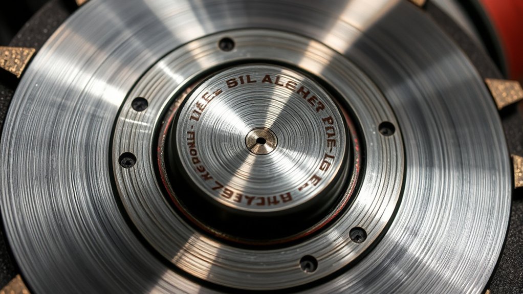
The arbor hole is the opening through the center of a wheel or disc. On many conventional U.S.-market angle grinders, the tool has a 5/8-11 threaded spindle, while the backing flange has a wider raised shoulder designed to center a 7/8-inch plain-hole disc.
The disc therefore does not need 7/8-inch threads. It slides over the smaller threaded spindle, rests against the backing flange, and centers on the flange shoulder. The outer lock nut then clamps the disc against the flange.
Note: One inch equals 25.4 mm, so 7/8 inch converts to 22.225 mm. Manufacturers commonly round and label this nominal wheel-hole size as 22.23 mm.
A small amount of designed clearance is not the same as a loose or incorrect fit. OSHA states that grinding wheels should fit freely rather than being forced onto a spindle. The wheel must still seat flat and be centered by the correct flange or mounting interface.
How to Choose the Right Arbor Hole Size for Your Grinder
Do not shop by arbor-hole size alone. Start with the grinder’s model number and manual, then compare every specification on the wheel label.
- Identify the mounting system. Determine whether the grinder uses a conventional threaded spindle and flange set, X-LOCK, or another model-specific interface.
- Match the wheel diameter. Never install a wheel larger than the maximum diameter listed on the grinder.
- Match the center mounting style. Confirm 7/8-inch plain hole, 5/8-11 threaded hub, X-LOCK, or the exact alternative specified by the manual.
- Match the wheel type and thickness. Cutting, grinding, flap, wire, and diamond accessories may require different hardware and guards.
- Match the material. The wheel must be labeled for the metal, masonry, concrete, tile, stainless steel, aluminum, or other material being worked.
- Check maximum speed. The wheel’s marked maximum RPM must equal or exceed the grinder’s rated no-load RPM.
- Confirm the guard and flanges. Use the guard and mounting hardware specified for both the grinder and wheel type.
Unthreaded 7/8-Inch vs. Threaded 5/8-11 Hubs
A 7/8-inch plain-hole wheel is clamped between a backing flange and an outer lock nut. It does not screw onto the spindle.
A 5/8-11 threaded-hub accessory has a built-in threaded center that screws directly onto a matching 5/8-11 spindle. Depending on the accessory and grinder manual, the conventional outer lock nut may not be used.
The two measurements describe different parts:
- 7/8 inch: the diameter of a plain wheel’s center hole or the centering shoulder it fits over.
- 5/8-11: a 5/8-inch-diameter spindle or hub with 11 threads per inch.
Understanding Arbor Hole Sizes and Mounting Systems
| Mounting System | How It Mounts | Compatibility Check |
| 7/8-inch or 22.23 mm plain hole | Slides over the spindle and centers on a backing-flange shoulder; an outer nut clamps it | Verify the grinder accepts that hole, wheel type, diameter, thickness, flange set, and guard |
| 5/8-11 threaded hub | Threads directly onto a matching conventional spindle | Confirm both thread diameter and pitch; do not force a mismatched metric or inch thread |
| X-LOCK | Clicks into a keyed tool-free mount and releases with a lever | An X-LOCK grinder requires an approved X-LOCK accessory; some X-LOCK wheels also fit conventional 7/8-inch mounts, but the reverse is not automatically true |
| Metric or other model-specific mount | Uses a metric spindle, proprietary flange, or another specified interface | Use only the wheel and hardware listed in the exact tool manual |
Compatibility With Grinder Models
Many conventional DEWALT and Milwaukee grinders sold in the United States use a 5/8-11 spindle, but that does not mean every disc sold for either brand uses the same mounting method. Wheel size, guard design, flange shape, speed, and product generation can differ.
Alternative systems are also available. Bosch documents that a conventional spindle grinder uses a backing flange and lock nut, while an X-LOCK grinder replaces those parts with a keyed tool-free mount. Check the exact tool model instead of relying on the brand logo.
Pro Tip: Photograph the grinder nameplate, guard markings, backing flange, and lock nut before buying replacement wheels. Comparing those details with the wheel package is more reliable than remembering only “5/8” or “7/8.”
Understanding Complete Disc Compatibility
A disc is compatible only when every part of the setup works together. Use this checklist before installing it:
- Mount: The plain hole, threaded hub, or quick-change interface matches the tool.
- Diameter: The wheel is no larger than the grinder and guard rating.
- Thickness: The wheel fits the flange set and guard without the lock nut bottoming out.
- Wheel type: Cutting, grinding, flap, diamond, and wire accessories are used only for their labeled operations.
- Material: The disc is approved for the workpiece.
- Speed: The wheel’s maximum RPM is not lower than the tool’s rated speed.
- Guard: The installed guard is approved for the wheel type and size.
- Hardware: The backing flange, outer nut, washers, and adapters are the approved parts for the exact tool.
- Condition: The wheel and mounting surfaces are undamaged, clean, and dry.
Do not enlarge a center hole, grind a flange, stack loose washers, machine your own reducer, or force incompatible threads together. A bushing or adapter is acceptable only when the wheel and tool manufacturers expressly approve it for that exact combination.
Products Worth Considering

INSTANT CONVERSION:With standard 5/8"-11 thread, this angle grinder adapter transforms tools into die grinders. A versatile grinder adapter supporting 1/4"(6mm) & 1/8"(3mm) bits for rotary carving and polishing tasks.

【Wrenches Combo Kit Good Coaxiality】Our angle grinder attachments offers excellent coaxiality, ensuring smooth rotation and grinding. You can expect a seamless grinding experience with a stable clamping mechanism that prevents slipping, making it incredibly convenient to use.
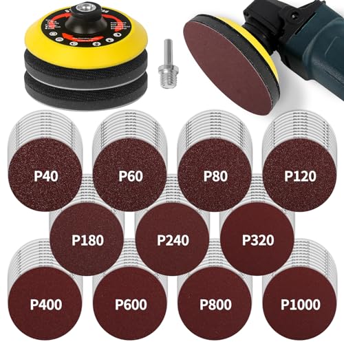
Turn Your Grinder into a Sander - The 5-inch heavy duty backing pad is used to hold sanding discs in an angle grinder. This assortment includes 110 sandpapers ranging from coarse to fine, catering to the needs of most customers. Includes 10 pieces each of 40/60/80/120/180/240/320/400/600/800/1000 grit.
Why RPM Ratings Matter for Safety
The maximum RPM printed on a disc is the highest speed at which that wheel is designed to operate. The grinder’s rated no-load speed must not exceed that number. For example, an 8,500-RPM wheel is not suitable for an 11,000-RPM grinder, even when the hole and diameter appear to fit.
The wheel’s marked maximum operating speed must be at least as high as the grinder’s rated spindle speed.
OSHA’s portable powered-tool standard requires the wheel to be inspected before mounting and the machine speed to be checked against the maximum operating speed marked on the wheel.
Wheel diameter also affects safe speed. A larger wheel designed for a slower large grinder must not be placed on a smaller, faster grinder. Removing the guard to create clearance does not make the setup acceptable.
How to Mount a 7/8-Inch Disc Safely
The exact parts and nut orientation vary, so use these steps with the instructions for your grinder and wheel.
- Disconnect all power. Unplug a corded grinder or remove the battery. Confirm the switch is off and wait for all movement to stop.
- Install the correct guard. Use the guard specified for the wheel’s type and diameter. A flat Type 1/41 cut-off wheel generally needs a cut-off guard, while a Type 27 depressed-center grinding wheel uses the guard specified for that shape.
- Inspect the parts. Check the wheel for cracks, chips, warping, water damage, an enlarged hole, or a damaged center ring. Inspect the guard, spindle, backing flange, and lock nut.
- Clean the mounting faces. Remove abrasive dust, metal chips, and other debris from the spindle, flange, nut, and wheel contact surfaces.
- Fit the backing flange. Install the original flange in the orientation shown in the grinder manual. It must sit fully against the spindle base.
- Seat the disc. Slide the 7/8-inch hole over the spindle and align it with the raised flange shoulder. The wheel should fit freely and rest flat without rocking.
- Install the outer lock nut. Use the correct side of a reversible nut for the wheel’s shape and thickness. This orientation differs by grinder and wheel, so follow the diagram in the manual.
- Tighten with the supplied method. Hold the spindle lock only after the tool has stopped, then tighten the nut enough to secure the wheel. Do not use impact tools or excessive force unless the manufacturer expressly directs it.
- Check clearance. Release the spindle lock and turn the disc by hand. It should rotate without rubbing the guard or wobbling.
- Perform a protected no-load check. Reconnect power, position the guard between you and the wheel, keep other people clear, and run the grinder without touching the workpiece for the interval specified by the manufacturer. Stop immediately if the wheel vibrates, rubs, or sounds abnormal.
The Milwaukee 2780-20 and 2781-20 operator’s manual illustrates cleaning and inspecting the mounting parts, aligning the wheel with the flange, and positioning the flange nut for different wheel thicknesses. The DEWALT DCG407/DCG408 manual also stresses power disconnection and selection of the correct guards, backing pads, and flanges.
Tips for Ensuring a Secure Arbor Hole Fit
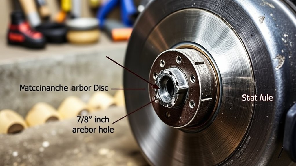
A secure setup comes from flat, undamaged contact surfaces and the correct clamping parts—not from forcing the center hole tightly against the spindle.
Verify Disc Compatibility Before Mounting
- Read the grinder nameplate and manual for wheel diameter, spindle or mount type, and rated RPM.
- Read the full wheel label for arbor size, maximum RPM, wheel type, dimensions, material, and permitted operations.
- Confirm the correct guard is installed and large enough to cover the specified wheel.
- Confirm the backing flange and lock nut are the approved parts for the grinder.
- Check that the lock nut can clamp the wheel without bottoming out on the spindle or flange.
Inspect the Arbor Hole and Mounting Hardware
The wheel hole should be round, clean, and free of cracks, crushed material, or an enlarged center. Do not use a wheel with a damaged center ring or a hole that has been filed, drilled, or otherwise altered.
Inspect the backing flange for bends, burrs, worn shoulders, or embedded debris. A damaged flange can prevent a good wheel from seating flat. Replace missing or damaged hardware with parts approved for the exact grinder model.
Troubleshooting Disc Fit Problems
| Problem | Likely Cause | Safe Correction |
| The disc will not slide into place | Wrong hole size or mounting system, damaged center, or debris on the flange | Stop and verify the part numbers; clean the approved hardware and never force or enlarge the hole |
| The wheel rocks before tightening | Wheel is not seated over the flange shoulder, flange is reversed, or contact faces are dirty | Remove the wheel, inspect the manual diagram, and reseat clean, undamaged parts |
| The nut is tight but the wheel remains loose | Wrong nut orientation, missing flange, unsuitable wheel thickness, or incorrect hardware | Do not operate the grinder; reinstall the specified flange and nut in the documented orientation |
| The wheel wobbles or vibrates | Damaged wheel, bent flange, debris, incorrect centering, or incompatible parts | Disconnect power, remove the wheel, and replace damaged or mismatched components |
| The disc rubs the guard | Wrong wheel diameter, incorrect guard, bent wheel, or misaligned guard | Use the specified wheel and guard; never remove the guard to gain clearance |
| A threaded accessory will not start smoothly | Wrong thread pitch, metric-versus-inch mismatch, damaged threads, or cross-threading | Stop immediately and obtain an accessory with the exact thread listed for the grinder |
Avoid These Common Arbor Hole Sizing Mistakes
- Assuming every grinder from one brand uses the same mount. Check the exact model and market version.
- Confusing the spindle thread with the wheel hole. A 5/8-11 spindle can use a 7/8-inch plain-hole wheel only when the correct flange system is designed for it.
- Forcing a wheel onto the tool. A bonded wheel should fit freely and seat flat.
- Using improvised reducers or washers. Loose hardware may interfere with flange contact and wheel clamping.
- Reversing the lock nut without checking the manual. The correct side may depend on wheel shape and thickness.
- Ignoring the guard type. A wheel that fits the flange may still require a different guard.
- Installing a wheel with a lower RPM rating. Physical fit does not make an overspeed setup safe.
- Mounting a larger wheel on a smaller grinder. The tool may run too fast and the correct guard will not fit.
- Side grinding with a cutting-only wheel. Thin Type 1/41 cut-off wheels are generally intended for peripheral cutting, not side pressure.
- Operating a wheel that wobbles. Stop, disconnect power, and correct the mounting problem before use.
How Different Disc Types Impact Cutting Performance
The wheel type determines how it should be mounted, guarded, and used. Do not select a disc by thickness or abrasive color alone.
| Disc Type | Primary Use | Key Limitation |
| Type 1/41 cut-off wheel | Straight cuts and notching when the label permits | Do not apply side pressure or grind with a cutting-only wheel; use the specified cut-off guard |
| Type 27 grinding wheel | Stock removal, weld grinding, shaping, and beveling | Use the labeled working angle and the specified Type 27 guard |
| Combination cut-and-grind wheel | Cutting and limited grinding when both operations are expressly printed on the wheel | Do not assume an ordinary cut-off wheel is a combination wheel |
| Flap disc | Blending, finishing, rust removal, and controlled stock removal | Use the working angle, backing support, and guard specified by the manufacturer |
| Diamond blade or wheel | Concrete, masonry, stone, tile, or another material specifically listed on the blade | Follow directional arrows, wet-or-dry restrictions, dust controls, and the required guard |
| Wire brush or wheel | Rust, scale, paint, and surface cleaning | Confirm thread or arbor fit, maximum speed, guard clearance, and protection from thrown wire fragments |
Aluminum oxide is widely used for general metalworking, while zirconia alumina and ceramic abrasives are often selected for demanding stock-removal work. The wheel must still be labeled for the material. For aluminum and other nonferrous metals, use an abrasive specifically approved for that application to reduce loading, glazing, and excess heat.
A specific 3M example, the 4-1/2-inch Type 27 grinding wheel with a 7/8-inch center hole, requires a guard designed for the wheel’s size and type and a grinder whose listed speed does not exceed the wheel rating.
Products Worth Considering

Premium and Value: This 10-pack 4-1/2 x 7/8-inch metal/stainless steel cut-off wheel set is specially formulated for fast cutting in metals and stainless steel

Structural Components: A Cut off wheel typically comprises an abrasive, a binder, and air holes. The abrasive cuts, the binder shapes and strengthens, and the air holes remove swarf and dissipate heat to prevent damage to the cutting disc from overheating

【Fits All 4-1/2 Inch Angle Grinders】 PRETEC Cut Off Wheel is compatible with all 4-1/2 inch angle grinders with 7/8 inch arbor. The high rotating speed of up to 13,300 RPM, more than common 13,000 RPM, ensure maximum efficiency.
Best Practices for Maintaining Your Angle Grinder and Discs
- Inspect before every use. Check the wheel, guard, spindle, handle, flange, lock nut, switch, cord, and battery interface.
- Keep mounting faces clean. Dust or metal particles between the wheel and flange can cause poor seating.
- Keep ventilation openings clear. Follow the tool manual’s cleaning method and avoid pushing debris deeper into the motor.
- Use original or approved mounting hardware. Do not substitute a generic nut merely because its threads appear to fit.
- Store wheels correctly. Keep them dry, protected from impacts and temperature extremes, and supported in the manner recommended by the wheel manufacturer.
- Discard questionable wheels. Do not use a wheel that was dropped, soaked, cracked, chipped, warped, altered, or damaged around the arbor hole.
- Follow the service schedule. Do not open or lubricate the grinder gearcase unless the manufacturer’s instructions direct you to do so.
- Use two-hand control. Install the side handle where it provides the best control and keeps the guard between you and the wheel.
- Control the work area. Clamp the workpiece when practical and direct sparks away from people, combustible materials, hoses, cords, batteries, and finished surfaces.
Use safety glasses and any additional face, hearing, hand, respiratory, or protective clothing specified by the grinder, wheel, material, and workplace instructions. A face shield adds protection but does not replace safety glasses.
Frequently Asked Questions
What is the most common arbor size for an angle grinder?
Many conventional U.S.-market angle grinders use a 5/8-11 threaded spindle. Plain-hole wheels for those tools often have a 7/8-inch or 22.23 mm center hole that fits over the backing-flange shoulder. These sizes are common rather than universal, so verify the exact grinder model.
Can you use a 7/8-inch disc on a 5/8-11 grinder?
Yes, when the grinder is specifically designed to mount a 7/8-inch plain-hole wheel with its backing flange and lock nut. The wheel slides over the 5/8-11 spindle and centers on the wider flange shoulder. Confirm the wheel diameter, type, thickness, RPM, guard, and hardware in the manual.
What size hole is used on an angle grinder disc?
A 7/8-inch or 22.23 mm plain hole is common on many angle grinder discs, but other sizes and systems exist. These include 5/8-inch plain holes, 5/8-11 threaded hubs, metric threaded hubs, and X-LOCK mounts. Read both the grinder manual and wheel label.
What does 5/8-11 arbor mean?
The designation means a 5/8-inch nominal thread diameter with 11 threads per inch. A matching 5/8-11 threaded accessory can screw onto that spindle. It does not mean that every plain-hole wheel should have a 5/8-inch center opening.
Is a 22.23 mm arbor hole the same as 7/8 inch?
They are normally the same nominal wheel-hole size. Seven-eighths of an inch equals 22.225 mm, which manufacturers commonly round to 22.23 mm. Always confirm the complete wheel specification rather than relying only on that conversion.
Can you use an adapter or bushing to change the arbor size?
Only when the wheel and tool manufacturers expressly approve the adapter or bushing for the exact setup. Do not use improvised washers, loose reducer rings, altered flanges, or homemade adapters. A permitted wheel-hole bushing must not interfere with the flange contact surfaces.
Can a plain 7/8-inch disc be used on an X-LOCK grinder?
Not unless the accessory is specifically approved for that X-LOCK mount. X-LOCK grinders require wheels with the keyed X-LOCK mounting interface. Some X-LOCK wheels are backward-compatible with conventional 7/8-inch spindle grinders, but an ordinary plain-hole wheel is not automatically compatible with an X-LOCK tool.
Why does an angle grinder disc wobble after installation?
Common causes include a damaged wheel, debris between the contact surfaces, a bent or reversed flange, the wrong lock-nut orientation, an enlarged arbor hole, incompatible mounting hardware, or a wheel that is not centered on the flange shoulder. Disconnect power and correct the problem before operating the grinder.
Conclusion
A 7/8-inch arbor hole is a common plain-hole mounting size, but it is only one part of angle grinder compatibility. On a suitable conventional grinder, the disc slides over a 5/8-11 spindle and centers on the backing-flange shoulder. It must fit freely, rest flat, and be clamped with the correct hardware.
Before operating the grinder, verify the wheel diameter, thickness, type, material rating, maximum RPM, guard, flange set, and lock-nut orientation. Disconnect power during installation, inspect every component, and stop immediately if the wheel rubs, loosens, or vibrates. When the wheel package and grinder manual disagree—or the parts do not seat exactly as shown—do not use the setup.
Sources
- OSHA 1910.243 — Guarding of Portable Powered Tools — wheel inspection, free spindle fit, bushings, guards, and maximum operating speed
- Milwaukee 2780-20 and 2781-20 Operator’s Manual — guard installation, wheel selection, flange cleaning, mounting, and flange-nut orientation
- DEWALT DCG407/DCG408 Instruction Manual — power disconnection, grinder wheel limits, guards, backing pads, and flanges
- Bosch TG503 Operating and Safety Instructions — conventional spindle mounting compared with X-LOCK mounting
- 3M 4-1/2-Inch Type 27 Grinding Wheel With 7/8-Inch Center Hole — wheel dimensions, guard requirements, and maximum-speed compatibility
- Norton Abrasives — What You Should Know About Grinding Wheel Guards — matching guards to grinding and cut-off wheel types