You might not realize how precisely a plasma torch shapes molten metal until you inspect its parts up close. You’ll learn how the torch, power supply, gas system, and controller each control arc stability, cut quality, and efficiency. Understanding these components helps you troubleshoot problems and optimize performance—so keep going to see which parts matter most and why.
What Is Plasma and Why It Matters in Cutting
Plasma is the fourth state of matter and it matters in cutting because ionized gas conducts electricity and delivers focused thermal energy you’ll use to sever metal.
Plasma, the fourth state of matter, becomes an ionized, conductive gas that delivers focused heat to sever metal.
You’ll rely on plasma properties like high temperature, electrical conductivity, and momentum to convert electrical energy into a confined, high-velocity jet that melts and ejects metal.
The ionization process is central: heat breaks gas molecules into ions and free electrons, creating a conductive channel that sustains the arc and concentrates energy at the kerf.
You’ll control parameters—amperage, gas flow, standoff distance, and traverse speed—to match plasma behavior to material thickness and conductivity.
Properly managed, the plasma jet reaches extreme temperatures and efficiently removes molten material, producing narrow, precise cuts with minimal cold work or distortion.
Understanding these plasma properties and the ionization process lets you optimize cutting quality, repeatability, and consumable life without needing to explore torch internals covered later.
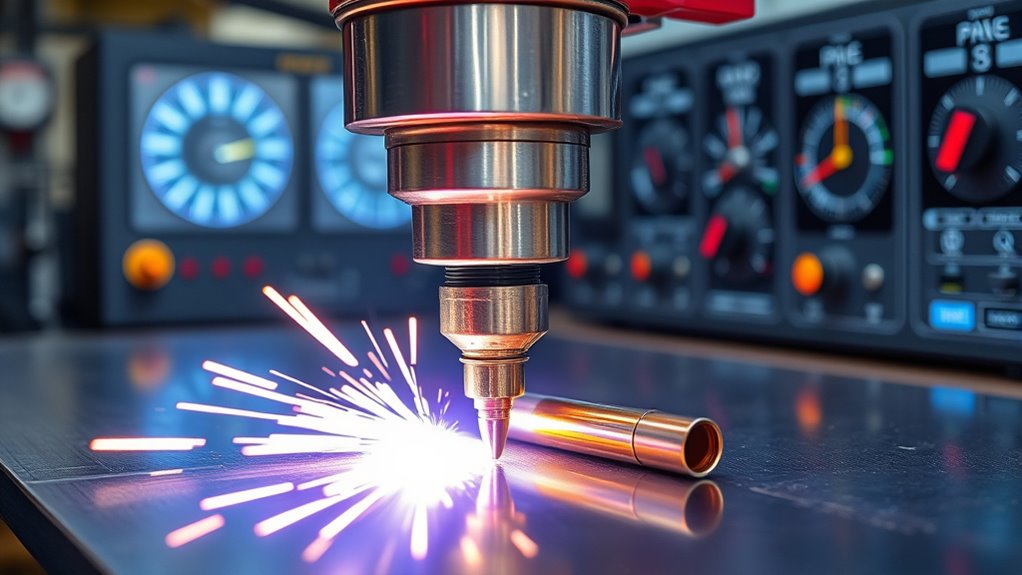
Plasma Torch: Core Components and Roles
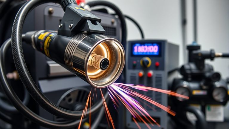
You’ve seen how ionized gas does the work; now look at the tool that makes and directs that ionization. The plasma torch is the machine’s core, generating the electric arc that ionizes gas and produces the cutting jet.
Its electrode initiates and sustains the arc; the nozzle constrains and shapes the plasma stream for precise material separation. The swirl ring creates a controlled vortex, centering the arc and stabilizing gas flow to maximize plasma efficiency. The shield cap absorbs sparks and molten spatter, protecting internal parts and improving operator safety.
You’ll keep performance predictable by following strict torch maintenance: inspect and replace the electrode and nozzle at intervals based on hours and wear, clean the swirl ring, and verify shield integrity.
Neglect increases arc instability, widens kerf, and reduces cut quality. Maintain consumables and gas pathways to preserve plasma efficiency and extend torch life, ensuring repeatable, high-accuracy cuts without compromising safety.
Power Supply and Its Influence on Performance
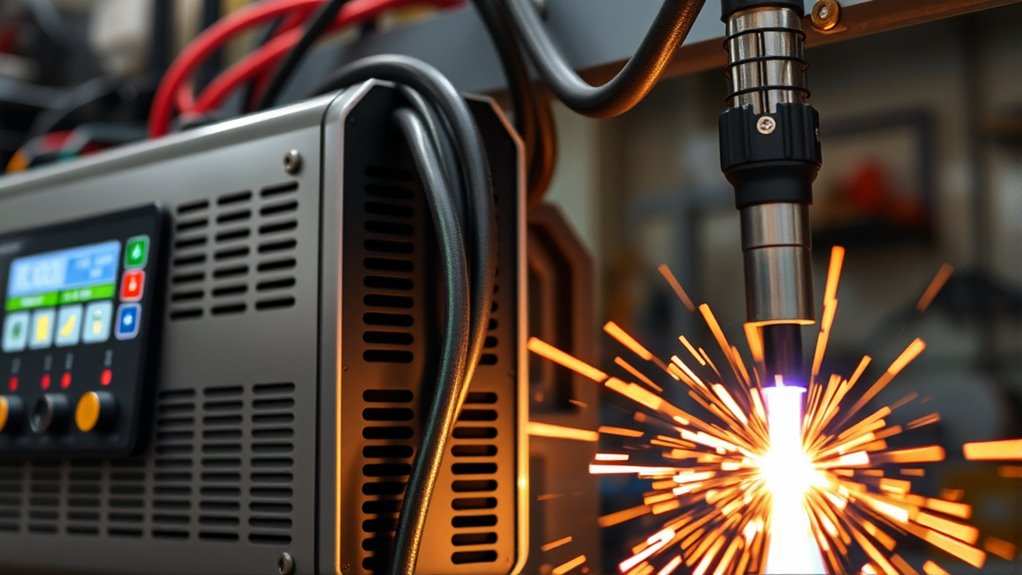
Because the power supply converts your shop’s AC line into the high-voltage DC needed to create and sustain the cutting arc, its design and regulation directly determine arc stability, cut speed, and edge quality.
You rely on the supply to transform line voltage into the 200–400 VDC range and to regulate voltage and current precisely; poor voltage regulation produces arc wander, inconsistent kerf width, and dross.
Select a unit sized for the amperage your material thickness demands, since undersized supplies force thermal limits and reduce cut speed.
Inverter-based designs deliver higher power supply efficiency, lowering operating costs and improving response for most non-heavy-duty tasks.
Robust regulation circuitry and thermal management maintain steady output under load transients, preserving cut quality.
In practice, you’ll prioritize units with tight voltage regulation, adequate duty cycle, and proven thermal protection to guarantee predictable arc behavior, repeatable edge quality, and efficient energy use across varying cut profiles.
Arc Starting Console and Ignition Systems
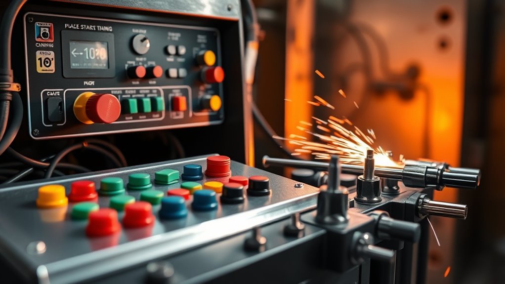
You’ll first review high-frequency ignition basics, where the ASC produces a ~5,000 VAC, multi-megahertz spark to reliably start the arc and then sustain it.
Compare pilot (HF start) versus contact (MCSP) methods so you can weigh reliability, consumable wear, and interference risks.
Finally, check ASC safety features—interlocks, shielding, and arc-stability monitoring—to prevent unstable arcs and extend component life.
High-frequency Ignition Basics
When the torch trigger’s pulled, the Arc Starting Console (ASC) fires a high-voltage, high-frequency spark—typically around 5,000 VAC at ~2 MHz—to ionize the cutting gas and initiate the plasma arc.
You rely on high frequency technology for reliable arc initiation across changing conditions; the HF pulse ionizes the gap so the main arc transfers cleanly to the workpiece.
The ASC sustains continuity once the arc forms, stabilizing the plasma stream and preserving cut quality.
Ignition system health directly affects cycle time and downtime, so you should monitor HF output, insulation integrity, and electrode wear.
Designs may use HF spark systems or alternative contact methods, but consistent ignition performance is essential for repeatable, high-quality cuts.
Pilot Arc vs. Contact
Although both pilot and contact methods rely on the Arc Starting Console to deliver the high-voltage pulse that initiates the plasma, they differ in where and how the arc forms: a pilot arc creates a stable, free-burning arc inside the torch before you touch the workpiece, while a contact arc only ignites on contact with the metal.
You’ll rely on the ASC’s ~5,000 VAC spark in either case, but pilot arc systems give cleaner starts and minimal dross formation, showing clear pilot arc advantages for precision and thick or contaminated material.
Contact arc methods are simpler but suffer greater contamination, rougher cut edges and arc instability — contact arc disadvantages that reduce quality on uneven or dirty surfaces.
Choose based on application and desired cut quality.
ASC Safety Features
A reliable ignition module is central to safe plasma cutting, and the Arc Starting Console (ASC) combines high-voltage spark generation, arc-maintenance circuitry, and interlocks to prevent accidental starts and keep the arc stable during cuts.
You rely on the ASC to initiate the plasma arc—either via high-frequency spark or modern contactless methods—and to sustain consistent performance through active arc-control circuits.
Built-in safety interlocks and fail-safe logic block unintended ignition and protect you from exposure.
Follow ASC operational guidelines: verify interlock integrity, inspect spark/contactless elements, and confirm grounding before each run.
Use ASC maintenance tips: replace worn electrodes, clean connections, and test arc-stability parameters.
Proper upkeep minimizes instability and reduces operator risk.
Gas Supply, Types, and Flow Control
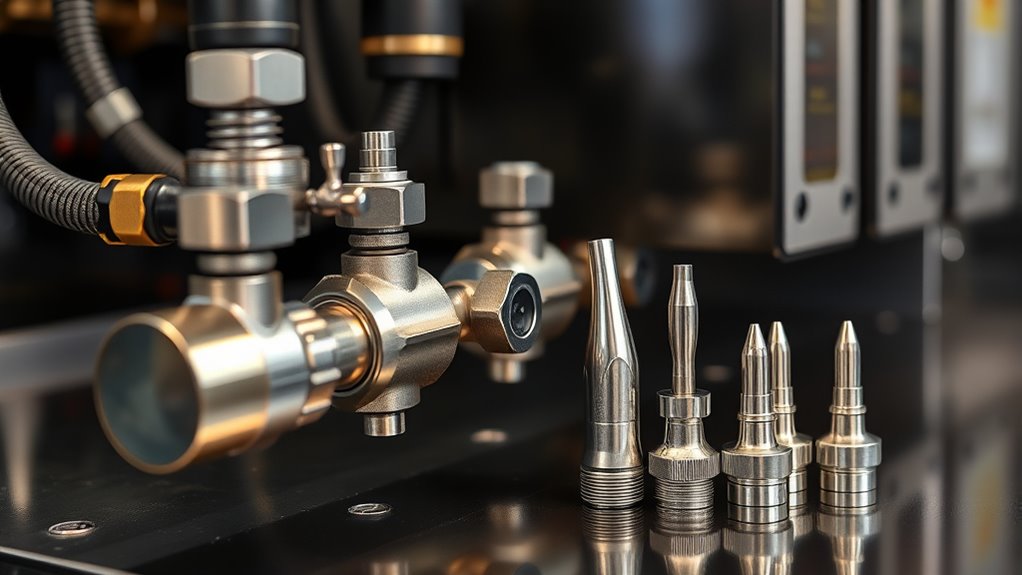
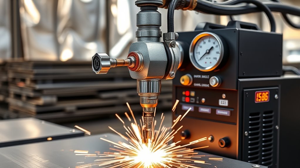
Since the plasma arc depends on a controlled gas stream, you need to select and regulate gas type and flow precisely to achieve stable arcs, ideal cut speed, and the desired edge finish.
You’ll choose among gas types—oxygen, nitrogen, argon, or shop air—based on material and finish: oxygen speeds through mild steel, nitrogen minimizes oxidation on stainless, and argon blends suit thin nonferrous metals.
Flow adjustments are handled at the gas console and by flow control valves that set pressure and volumetric rate to maintain arc stability and a narrow kerf.
You’ll monitor and tune flow to prevent excessive spatter, taper, or dross.
Valves and pressure regulators provide repeatable settings; the console lets you switch gases and fine-tune outputs per program or job.
Consistent supply pressure, proper tubing, and leak-free fittings are essential for precision cuts.
Proper gas selection and disciplined flow control directly determine cut speed, edge quality, and overall process reliability.
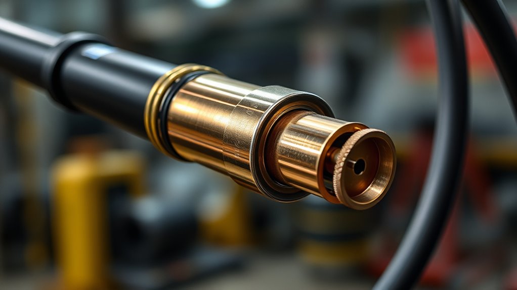
Nozzles, Electrodes, and Consumables Explained
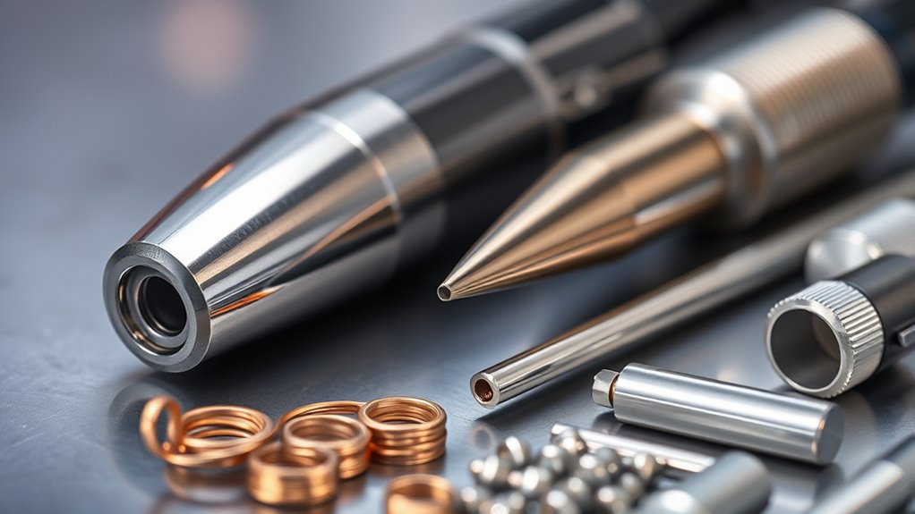
The nozzle and electrode are the core consumables that shape the plasma arc and determine cut consistency, kerf width, and operating cost, so you’ll monitor wear and replace components proactively.
The nozzle directs and shapes the plasma stream; matching nozzle types and size to material thickness optimizes cut quality and kerf width. Different nozzle types (orifices, swirl designs) control gas flow, constriction, and cooling, so select the type that fits your application.
The electrode generates the arc that ionizes gas into plasma; electrode lifespan is short under heavy use—typically 1–2 hours—so you’ll plan replacements to maintain efficiency.
Worn consumables widen kerf, reduce precision, and increase dross and restart time. Inspect nozzles for pitting and electrodes for tip erosion, and keep spare kits indexed by material and thickness.
Routine consumable maintenance preserves cutting speed, repeatability, and operating cost control without altering machine control or software settings.
CNC Controller and Cutting Software Integration
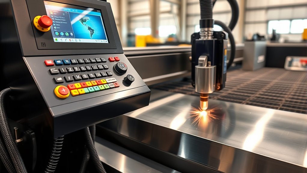
You’ll rely on the CNC controller to convert CAD/CAM outputs into precise motion control commands that position the torch to tenths of a millimeter.
The cutting software generates optimized toolpaths and G-code while managing feed rate, direction, and cut parameters to preserve geometry and reduce waste.
Together they enable real-time adjustments and closed-loop monitoring so you maintain consistent cut quality across production runs.
Motion Control Accuracy
While integrating the CNC controller and cutting software, you get precise motion control that translates CAD geometry into exact torch coordinates and timing.
You rely on the CNC to convert designs into numerical coordinates and the cutting software to generate G-code that dictates speed, direction, and pierce timing.
Motion control accuracy guarantees repeatability so identical parts are produced at volume. You adjust parameters for material type and thickness to optimize cut quality, and real-time feedback lets the system correct feedrate and torch height on the fly.
This precision enhancement reduces scrap, shortens cycle time, and maintains edge quality.
Implement strict calibration and closed-loop feedback for consistent, measurable motion control performance across production runs.
CAD/CAM Workflow
When you move from CAD to CAM, you create a precise digital workflow that turns design geometry into machine-ready G-code and drives the CNC controller to execute exact torch motion.
You start in CAD to define cutting specifications and shapes, then use CAM for design optimization and nesting to minimize scrap. The CAM generates G-code the CNC controller reads to control torch travel, feed rates, and pierce sequencing.
Software integration enables real-time adjustments, monitoring, and feedback for consistent part quality and repeatability in high-volume runs.
- Reduce material waste
- Improve repeatability
- Enable live process control
You’ll rely on robust cutting software and controller compatibility to maintain accuracy, throughput, and predictable production outcomes.
Plasma Table Design, Slats, and Hold-Down Systems
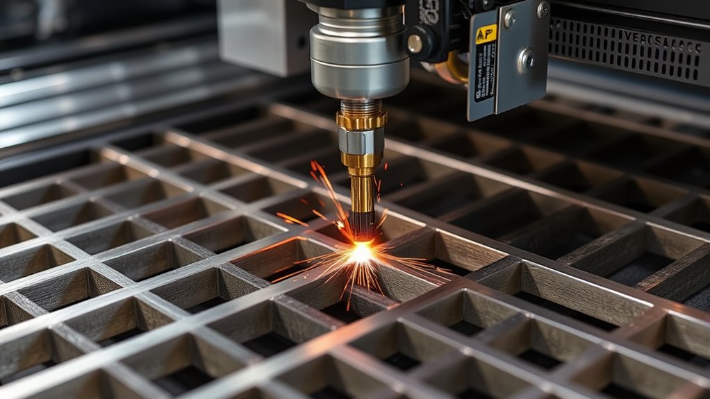
Because a plasma table needs a flat, stable surface to hold metal precisely, its design centers on rigid frames, replaceable slats, and reliable hold-down systems that together control movement, heat, and debris during cutting.
You rely on plasma table stability to maintain tolerances; a rigid frame resists torsion and vibration so the torch follows programmed toolpaths accurately.
Slats support the workpiece and channel slag away; designing for slat replacement simplifies maintenance and keeps the cutting plane even as slats wear or warp.
Hold-down systems—mechanical clamps, pneumatic fixtures, or magnetic devices—secure material to prevent shift during pierce and traverse stages, eliminating seam wander and miscuts.
Integrated water trays beneath slats capture sparks, reduce visible smoke, and protect table components without replacing ventilation discussion here.
Configure slat materials and clamp locations to balance thermal absorption, ease of debris removal, and accessibility for replacement, ensuring consistent part quality and minimizing downtime.
Cooling, Ventilation, and Safety Systems
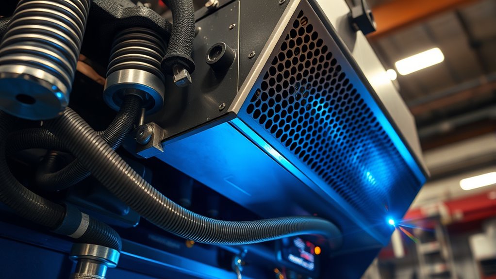
A robust cooling, ventilation, and safety suite completes a plasma table’s functional design, protecting consumables and operators as slats, frames, and clamps guide the cut.
You’ll rely on cooling efficiency to prevent torch and consumable overheating during prolonged cycles; closed-loop coolant, water trays, or misting systems capture sparks and lower part temperatures, extending component life.
Ventilation design removes fumes, smoke, and gases at source, preserving air quality and visibility.
You should prioritize three core controls:
- Active coolant circulation and temperature monitoring to maintain cooling efficiency.
- Local exhaust and room ventilation design that captures particulates and directs exhaust safely.
- Automatic shutdowns and interlocks that trigger on overtemperature, low coolant, or system faults.
Maintain ventilation filters, coolant levels, and purge paths regularly to prevent fire, equipment failure, and hazardous exposure.
These systems work together to guarantee operational continuity, compliance with safety standards, and reduced consumable costs.
Factors That Affect Cut Quality and Kerf
Cut quality and kerf are governed by a handful of controllable variables you need to monitor and adjust precisely. You’ll control cutting speed, amperage, standoff distance, gas type/flow, and technique to optimize results. Faster cutting speeds usually yield a narrower kerf; higher amperage widens kerf through greater heat input. Increase standoff distance and arc voltage shifts, producing a wider, less precise kerf. Choose gas and flow to match material and desired edge quality. Your skill with cutting techniques determines consistency; poor technique causes variable kerf widths and dross.
| Variable | Effect on Kerf | Actionable Control |
|---|---|---|
| Cutting speed | Faster = narrower kerf | Tune feed rate |
| Amperage | Higher = wider kerf | Reduce for thin stock |
| Standoff | Greater = wider kerf | Maintain torch height |
| Gas type/flow | Alters arc temp & kerf | Use recommended gas |
| Operator technique | Consistency | Train and practice |
Use kerf measurement to verify settings and iterate until cuts meet tolerance.
Frequently Asked Questions
Can Plasma Cutting Machines Cut Non-Conductive Materials Like Plastics or Wood?
No, you can’t reliably plasma cutting non conductive materials like plastics or wood; plasma cutting requires conductive workpieces, and using it on non conductive materials risks poor cuts, toxic fumes, and fire hazards—use laser, waterjet, or CNC routers.
How Do Plasma Cutters Compare to Laser Systems for Thin Stainless Steel?
You’ll see plasma efficiency as faster, rougher cuts and higher material removal, while laser precision gives cleaner, narrower kerfs and finer detail; you’ll choose plasma for speed and thickness, laser for spotless edges and tight tolerances.
Can Handheld Plasma Torches Be Used for Precision Artistic Work?
Yes — you can use handheld plasma torches for precision artistic work; you’ll need steady precision control, fine consumables, proper artistic techniques, slow consistent motion, and practice to achieve detailed cuts while managing heat, kerf, and dross removal.
What Maintenance Schedule Keeps Consumable Costs Minimized Long-Term?
Like a metronome keeping rhythm, you’ll schedule preventive maintenance weekly, monthly, and annually to inspect consumables, clean torch/nozzles, calibrate settings, and track usage; these cost effective strategies cut downtime, extend life, and lower long-term costs.
Are There Portable, Battery-Powered Plasma Cutters for Remote Jobs?
Yes — you can get portable plasma cutters powered by batteries; you’ll evaluate battery efficiency, duty cycle, and inverter design, ensuring power density and consumable compatibility meet remote-job requirements while managing weight, runtime, and recharge logistics.
Conclusion
You’ve seen how each plasma cutting part — from torch electrode and nozzle to power supply, gas system, CNC controller, and table — plays a precise role in cut quality and safety. Maintain components, control gas flow and cooling, and tune arc-starting and software parameters to get repeatable kerf and minimal dross. Like a steam engine with microchips, you’ll achieve reliable, efficient cuts when you inspect, replace wear parts, and follow calibrated operating procedures.