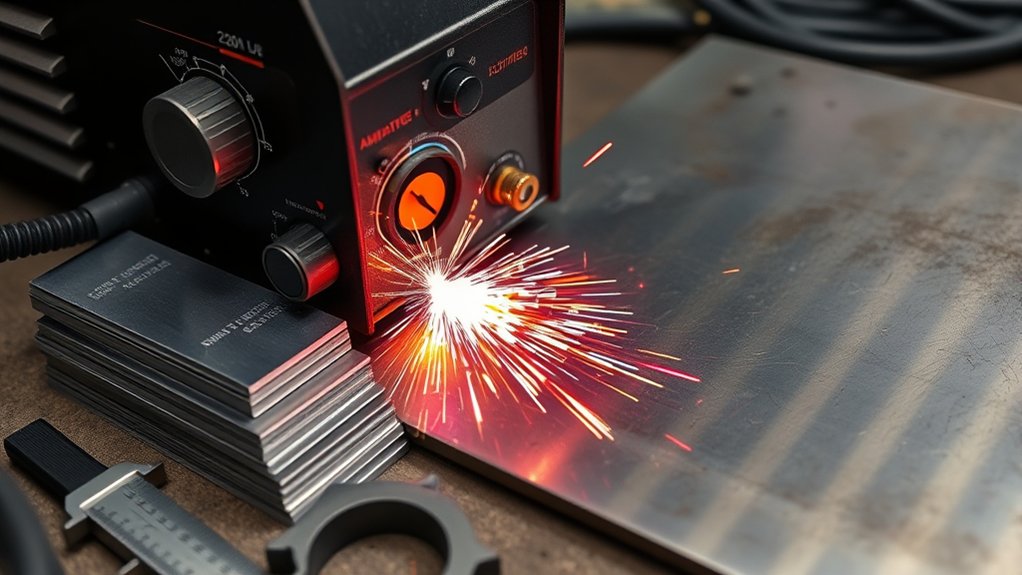
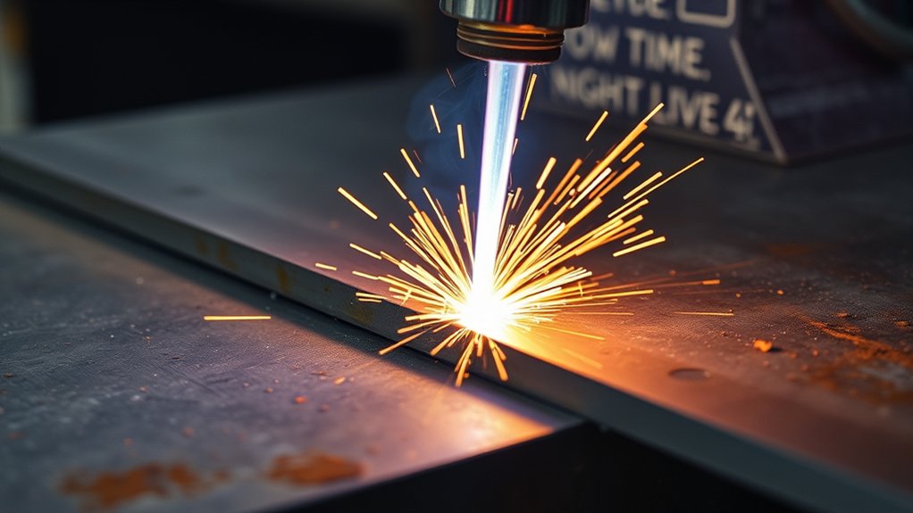
When you run a plasma cutter on 220V, your amperage setting dictates real cut capacity and duty cycle. As a rule: ~20 A handles 1/8 in, add ~10 A for each additional 1/8 in; around 50 A is appropriate for 1/2 in steel with clean kerf and speed. Match tip orifice and gas flow to amps, and size the circuit correctly to avoid voltage sag. But thickness ratings shift by metal type and cut quality targets.
Understanding 220V Power and Plasma Cutter Input Limits
For 220V plasma cutters, match input current capacity to the cut thickness to avoid nuisance trips and voltage sag. You should size the branch circuit and breaker to the machine’s maximum input draw, not just the rated output amps, to maintain power efficiency and amperage safety.
A practical baseline is 20 A input for up to 1/8 in, adding roughly 10 A per additional 1/8 in. That puts typical needs near 40 A for 3/8 in and about 50 A for 1/2 in, balancing cut speed and kerf quality.
Account for arc length: longer arcs can push input toward 44 A on a 220V line, so avoid undersized circuits. The Hypertherm Powermax45 XP operates efficiently on a 30 A circuit under 1/2 in, but step up to 50 A for thicker work to prevent breaker trips.
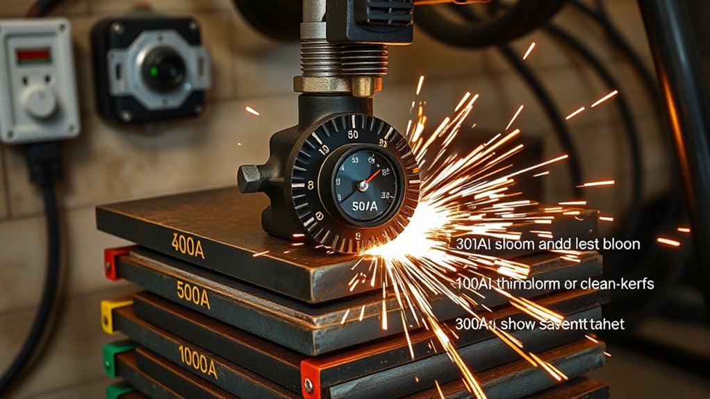
Amperage-to-Thickness Guidelines for Common Metals
Building on input capacity and breaker sizing, match output amperage to material and thickness using quantifiable targets. For mild steel, use 20 A up to 1/8 in; add 10 A for each additional 1/8 in (e.g., 30 A for 1/4 in, 40 A for 3/8 in, 50 A for 1/2 in). This keeps arc energy aligned with thickness and plasma efficiency.
Account for metal properties. Stainless steel typically needs more energy density: target 40 A for 3/8 in and 50 A for 1/2 in to sustain cut speed and edge quality. Aluminum tracks similarly to mild steel at these ranges; 40 A is appropriate for 3/8 in aluminum.
Select equipment accordingly. A Hypertherm Powermax45 XP supports high-quality cuts to 1/2 in at 50 A on a 50 A circuit; you can run it on a 30 A circuit for thinner stock with reduced duty cycle headroom.
For manual cutting, prioritize max power settings to maintain kerf stability, speed, and precision on intricate paths.
Matching Tip Size and Consumables to Amp Settings
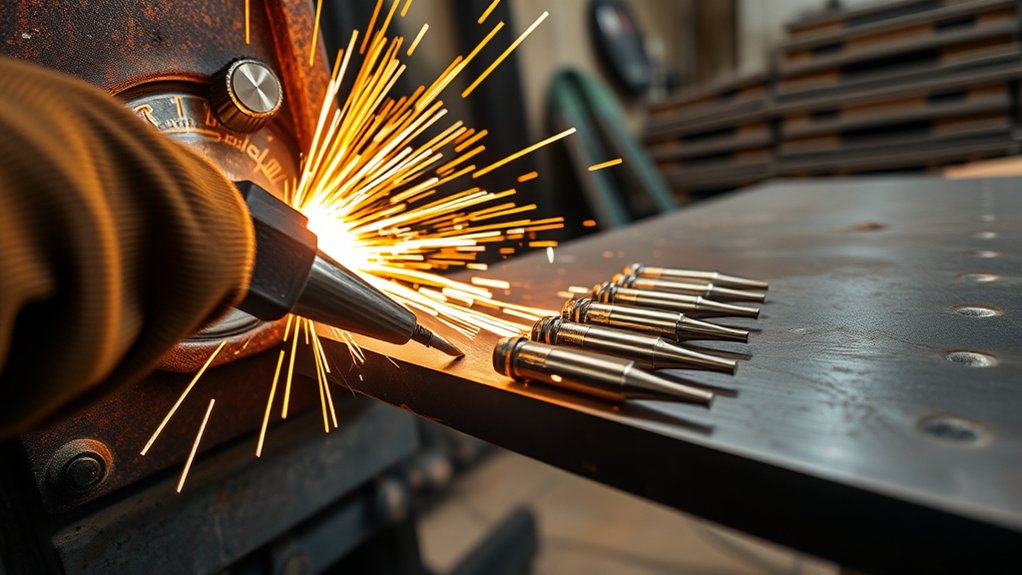
Two variables govern cut quality at a given thickness: amperage and the consumable set (nozzle orifice, shield, and electrode). Match amp output to both metal thickness and tip selection; then choose consumable types that stabilize the arc and control kerf. At 20 A you’ll cut up to 1/8 in; add ~10 A per additional 1/8 in. Wider tips increase kerf and dross; precision orifices maintain a tight, high-energy stream. On systems like the Hypertherm 45XP, plan ~50 A for 1/2 in, verifying arc voltage and gas flow.
| Thickness | Amps (guideline) | Consumables |
|---|---|---|
| ≤1/8 in | 20 A | FineCut: narrow kerf, stiff arc |
| 1/4–3/8 in | 30–40 A | Standard: balanced kerf, life |
| 1/2 in | ~50 A | High-amp precision tip, robust shield |
Use FineCut on thin stock for best edge quality; switch to standard or high-amp precision designs as thickness increases. Monitor amperage closely—low input voltage can drive higher current draw, affecting cut stability and efficiency.
Duty Cycle Considerations at Different Amp Levels
Although amperage drives thickness capability, it also dictates thermal load and duty cycle, so you must size and run the machine within its rated intervals.
Amperage enables thickness but raises thermal load—size and operate within rated duty cycle limits.
Duty cycle is the percentage of a 10‑minute period the cutter can operate without exceeding thermal limits. As amps rise, arc power and internal heat increase, reducing duty cycle efficiency and requiring stricter thermal management.
Use manufacturer data to plan cut/cool timing. For example, a Hypertherm Powermax 45 XP is rated 35% at 40 A—3.5 minutes cutting, 6.5 minutes cooldown.
If your workflow demands longer arcs at higher amps, select a unit with a higher rated duty cycle at that current, or stage operations to avoid thermal saturation.
Lower amperage extends duty cycle and continuous runtime but trades off cut thickness and travel speed.
Match amperage to material and volume, monitor over‑temperature indicators, and maintain clean filters and unobstructed airflow.
Properly sizing the machine prevents overheating, protects components, and sustains consistent cut quality.
20–30A Settings: Best Practices for Thin Sheet Cutting
At 30A, you should match amperage to thickness (≤6.4 mm/0.25 in typical) and adjust for alloys like stainless that need tighter margins.
Maintain about 125 mm/min (5 ipm) to control heat input, pair with FineCut consumables for a narrower kerf and stable arc, and verify kerf width in test coupons.
Secure thin sheets with low-profile clamps or magnetic fixtures on a flat, grounded surface to prevent flutter, and monitor input current to avoid nuisance trips on a 30A circuit.
Amperage-To-Thickness Guide
When you dial a plasma system to 30 A, you’re in the sweet spot for thin sheet work: expect clean, efficient cuts on mild steel up to 1/4 in (6 mm), with best edge quality on ≤1/8 in (3 mm) if you drop toward 20–25 A.
Apply disciplined cutting techniques and safety precautions: use FineCut consumables at lower amperage to narrow kerf and reduce dross, verify torch-to-work distance per OEM spec, and guarantee clean, dry air.
Use ≥20 A for sheets up to 1/8 in (3 mm). Hold 30 A for 3/16–1/4 in to balance quality and throughput.
If you step to 3/8 in (9.5 mm), plan on ~40 A to sustain arc stability and limit heat input.
Monitor circuit loading—running 30 A on a 30 A breaker risks nuisance trips and voltage sag.
Speed and Kerf Control
With the amperage-to-thickness baseline set, focus on 30A speed and kerf control to protect edge quality on thin sheet. At 30A, limit material thickness to 1/8 in; beyond that, increase current by ~10 A per additional 1/8 in.
For thin sheet, target a travel speed near 125 mm/min (5 ipm) to balance cut quality and heat input. Verify by observing a slight drag line angle and minimal dross.
Use FineCut consumables to narrow the kerf and increase dimensional accuracy. Maintain consistent standoff and perpendicular torch alignment to keep kerf width uniform.
Favor higher travel speed when cutting polished stainless or aluminum to reduce heat-affected distortion and melting. Monitor arc sound and pierce delay; adjust speed in small increments to prevent lag lines and widening kerf.
Secure Fixturing Methods
Though thin sheet cuts at 30A demand high travel speeds, you’ll only hold tolerance and flatness if the workpiece can’t move: fixture the sheet rigidly using low-profile clamps, magnetic squares, or vacuum pods to prevent lift, slide, and chatter under arc force. Apply fixturing techniques that resist thermal drift on low-rigidity alloys (polished stainless, aluminum). Use FineCut consumables for a narrow kerf and stiff arc; they reduce lateral force and improve precision when securing materials.
| Method | Purpose |
|---|---|
| Low-profile clamps | Block sheet creep; maintain datum |
| Magnetic squares | Stabilize edges; quick reposition |
| Vacuum pods | Uniform hold-down; minimize distortion |
| Sacrificial slats + weights | Dampen vibration; protect kerf exit |
Set amperage per thickness: ~20 A for ≤1/8”, add ~10 A per additional 1/8”. Short pierce delay when not edge-starting; increase for stacked sheets.
35–45A Settings: Medium-Thickness Performance and Speed
At 45A, you operate in the ideal amperage range for medium stock—precise cuts above 1/8 inch and clean performance on mild steel, stainless, and aluminum up to 1/2 inch.
You should set cut speed to maintain kerf quality; for thin tests like 16 ga, target energy delivery consistent with ~3.5 kW to minimize heat input and warping.
Adjust amperage and travel speed iteratively to meet tolerance: increase speed to reduce HAZ when surface finish is acceptable, or back off speed slightly for tighter edge quality and squareness.
Optimal Amperage Range
For medium-thickness work, a 40–45 A setting delivers the best balance of cut quality and speed on materials around 3/8 in (9.5 mm) and supports clean severing up to 1/2 in (12.7 mm) on systems like the Hypertherm Powermax45 XP. You’ll see predictable amperage effects: arc density high enough to maintain kerf integrity, yet controlled heat input to protect cutting performance on mild and stainless steel. At 45 A, you can sustain efficient travel rates while avoiding excessive bevel or rough edges.
| Thickness | Recommended Amps | Outcome |
|---|---|---|
| 1/4 in (6.4 mm) | ~35 A | Smooth pierce, minimal dross |
| 3/8 in (9.5 mm) | 40–45 A | Ideal quality, fast travel |
| 1/2 in (12.7 mm) | 45 A (sever) | Clean sever, controlled HAZ |
As a rule, increase ~10 A per additional 1/8 in.
Cut Speed Vs Quality
When you run 45 A on 3/8 in mild steel, matching travel speed to the arc’s energy density is what preserves edge quality and productivity.
Target a travel speed in the 20–40 ipm window; slower than 20 ipm elevates heat input, widens kerf, and risks warping, while faster than 40 ipm undercuts penetration and leaves dross.
Monitor cut quality indicators: a square, oxide-light edge, minimal top spatter, and ejecting sparks angled 10–20° from vertical.
Use FineCut consumables when you need a narrower kerf and a more stable arc for intricate geometry.
They allow slightly higher travel speed at equal quality. Verify results with test coupons, then lock parameters: amperage 45 A, standoff within spec, dry air, and nozzle condition documented per your procedure.
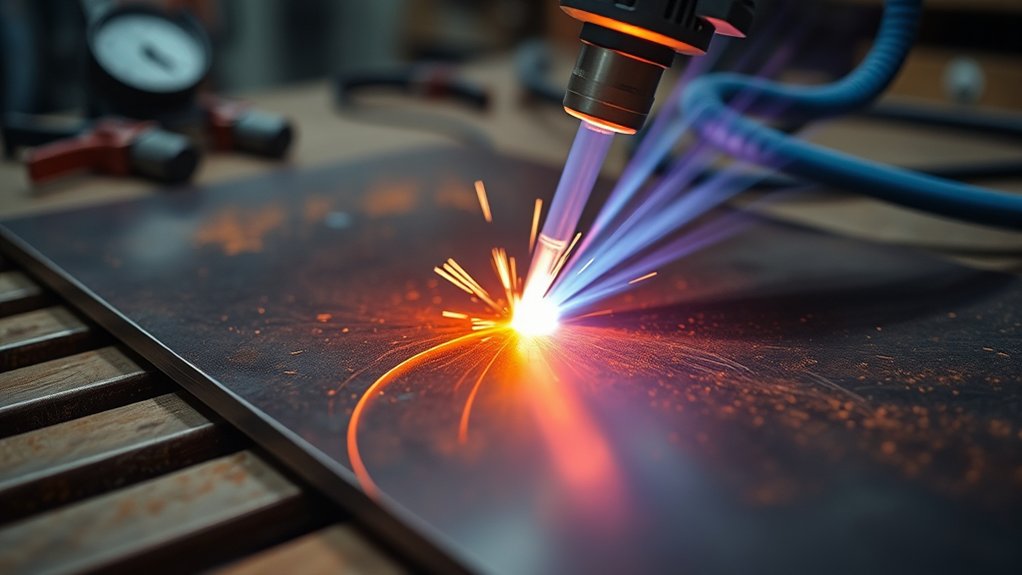
50–65A Settings: Maximum Capacity and Severance Cuts
Set to 65 amps, a modern air plasma cutter delivers clean, precise cuts in mild steel up to 1.00 in (25.4 mm) and can sever to 1.25 in (31.8 mm) with reduced edge quality and slower travel. At this setting, you’re operating at the maximum capacity for clean cuts; beyond that, treat results as severance cuts.
Expect kerf widening, increased dross, and less square edges at 1.25 in.
Use approximately 60 PSI dry, stable air to sustain arc density, limit nozzle erosion, and maintain dimensional accuracy. Match travel speed to amperage and thickness: 65A supports higher inches-per-minute on 3/8–3/4 in stock and controlled, slower passes at 1 in.
Maintain proper standoff with a shielded nozzle and verify pierce height and delay per manufacturer tables to avoid double-arcing and tip wear.
Monitor duty cycle at 65A—continuous cutting near rated limits risks thermal shutdown. Plan intermittent cuts or cooldown intervals to keep output stable and consumable life predictable.
Managing Heat, Warping, and Cut Quality at High Amps
You’ll tune travel speed to match amperage and thickness—e.g., target ~40 A on 16 ga with high IPM to limit heat input, and reduce amps if kerf widens or dross increases.
Use rigid fixturing for thin sheets (full support, clamps, or vacuum hold-down) to prevent oil-canning and maintain consistent standoff under thermal load.
Verify results with cut coupons: measure kerf width, HAZ, and flatness, then adjust speed ±10% and amperage in 5–10 A steps to meet your cut-quality criteria.
Travel Speed Tuning
Although higher amperage releases thicker, faster cuts, you must tune travel speed to control heat input, warping, and kerf width. Use travel speed optimization within your plasma cutting techniques to align current, speed, and material response. At higher amps, increase speed to limit heat propagation and maintain a narrow kerf, especially on stainless. If you see dragging dross or a wide kerf, you’re too slow; if you see arc lag or bevel, you’re too fast. Validate with short test coupons, then lock parameters.
| Amperage (A) | Stainless (mm) | Target Speed (mm/min) |
|---|---|---|
| 40–50 | 1.0–1.5 | 1,800–2,400 |
| 60–70 | 2.0–3.0 | 1,200–1,800 |
| 80–100 | 3.0–6.0 | 700–1,200 |
Monitor kerf width and dross as primary indicators; adjust speed in 5–10% increments to balance quality and minimal heat input.
Fixturing Thin Sheets
Two priorities govern fixturing thin sheets at high amps: rigid restraint and controlled heat input. Use fixturing techniques that clamp the perimeter and bridge the cut path to maintain sheet stability.
Apply low-mass, closely spaced hold-downs or vacuum tables to minimize flexing and sliding—critical for polished stainless and aluminum. Pair restraint with high travel speeds; target ~125 mm/min (5 ipm) to limit heat propagation and reduce distortion.
Standardize pierce control: minimize pierce delay, especially when stack cutting, because lower layers see greater kerf and lagging melt ejection.
Validate with a top-to-bottom coupon test and adjust delay in 0.05–0.10 s increments. For cut quality, specify FineCut consumables to achieve a narrower kerf and stiffer arc at higher amperage.
Document fixture layout, speed, and pierce settings for repeatability.
Electrical Circuit and Breaker Sizing for 220V Plasma Cutters
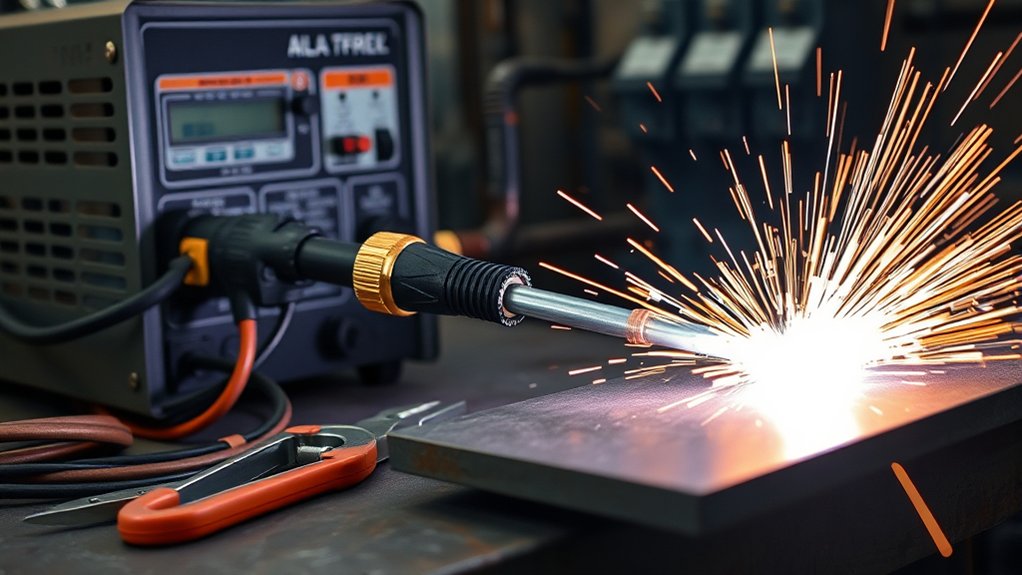
When sizing the electrical supply for a 220V plasma cutter, match the breaker and conductors to the machine’s peak draw and duty cycle to prevent nuisance trips and overheating.
Size the breaker and conductors to peak draw and duty cycle to prevent trips and overheating.
Verify circuit compatibility and select breaker types that align with manufacturer specs and local codes. For cutters like the Powermax45 XP, expect up to 44A draw; a 50A breaker with 6 AWG copper conductors provides margin and thermal capacity for thicker cuts.
For light work under 1/2 inch, a 30A circuit can be feasible, but any setting that pushes above 30A risks tripping. As material thickness drives amperage toward or past 40A, use a 50A circuit to maintain stability.
Keep cable length reasonable to limit voltage drop. Use appropriately rated receptacles and plugs (NEMA 6-50 common). Confirm breaker curves and avoid tandem loads on the same branch.
Balance amperage settings with circuit capacity, and upgrade wiring when increasing breaker size to maintain safe ampacity.
Sample Cut Charts: Steel, Stainless, and Aluminum by Amps
Start with amperage as your primary variable and map it to material and thickness. For mild steel at 220V, budget 20 A for 1/8 in, then add 10 A per additional 1/8 in. Stainless prefers higher energy density: 40 A targets 3/8 in with balanced speed and cut quality; up to 50 A yields clean 1/2 in, with severance near 3/4 in at higher amps. Aluminum needs 10–20 A less than steel at the same thickness, improving kerf management and heat input.
| Setting | Guidance |
|---|---|
| Steel, 1/8–3/8 in | 20–40 A; add 10 A per 1/8 in |
| Stainless, 3/8–1/2 in | 40–50 A; clean to 1/2 in |
| Aluminum, match thickness | Steel amps minus 10–20 A |
Use the table to select an initial current, then verify with test coupons. Tune travel speed to keep a slight rear drag and full dross release. If kerf widens or bevel increases, reduce amperage or increase standoff; if lag lines trail, increase amperage or speed.
Frequently Asked Questions
Can I Run a Plasma Cutter From a Generator, and What Specs Are Required?
Yes, you can. Verify generator compatibility: continuous wattage ≥ 1.5× cutter input, surge ≥ 2×, THD ≤ 5%, voltage ±10%, frequency 60/50 Hz. Match power requirements: 120/240 V, phase, plug, duty cycle, and recommended 30–50% overhead.
How Does Air Quality or Moisture Affect Cut Performance and Consumable Life?
Air quality and moisture control directly affect arc stability, kerf width, dross, and oxide formation. You’ll see shorter consumable life, erratic starts, and taper. Use <10% RH, -40°F PDP dryers, 0.01–0.1 micron coalescing filters, and frequent drain cycles.
What Personal Protective Equipment Is Recommended Beyond a Welding Helmet?
You should wear safety goggles meeting ANSI Z87.1+, flame-resistant jacket (ASTM F1506), leather gloves types rated for heat/cut (EN 388/407), hearing protection (NRR≥25 dB), steel-toe boots, respirator (P100 per OSHA/NIOSH) when fumes exceed thresholds, and fire-resistant sleeves.
Are There Emi/Rfi Interference Concerns With Nearby Electronics or CNC Controllers?
Yes. Studies show 30–40% of uncontrolled shop EMI incidents affect digital controls. You should mitigate electromagnetic interference for CNC controller compatibility: use shielded cables, star-grounding, ferrites, line filters, IEC 61000-6-2 compliance, separated power/signal routing, proper bonding, and surge protection.
How Do I Safely Transport and Store the Plasma Cutter and Consumables?
Use rigid cases and padded restraints for transport methods; secure leads, lock-out power, keep cylinders upright. Store in dry, 5–35°C storage conditions, 30–60% RH, dust-free, off-floor. Segregate consumables, label batches, cap torches, desiccate, follow manufacturer SDS and IEC/ANSI handling guidelines.
Conclusion
You’ve mapped amps to inches like a calibrated gauge, so your 220V plasma cuts will track true. Set 20–30A for crisp sheet work; step 10A per added 1/8 inch; push 50–65A for 1/2-inch capacity and severance. Match tip size, watch duty cycle, and size your breaker to the spec. Control heat like a metronome—speed, standoff, and gas flow lock in standards-grade edges. With cut charts as coordinates, your kerf runs straight as a laser line.