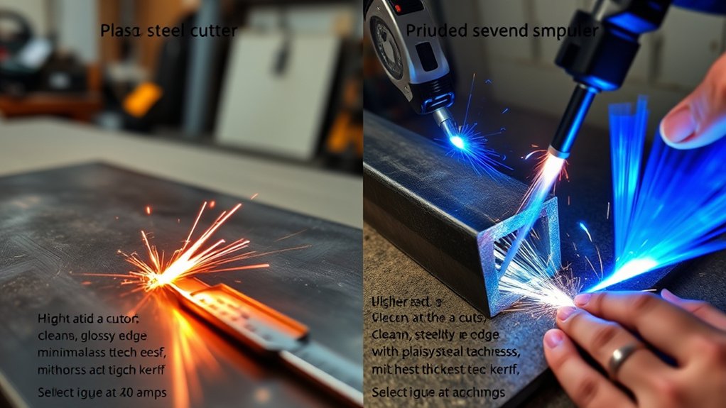
If you run a 40-amp plasma cutter, you will face a choice between clean cuts and severance cuts. Expect clean, low-dross cuts up to 1/4 inch (6 mm) thick. You must use the recommended speeds and standoff distances based on manufacturer specs. You can sever metal close to 1 inch (25 mm) thick, but this leaves heavy dross and bevels, and requires slow travel speeds. Duty cycle, arc start type, and consumables also change your results. Because of this, you will want to match your technique and machine to the thickest material you cut regularly.
Quick Answer
- A clean cut on a 40-amp plasma cutter usually maxes out around 1/4 inch, leaving a smooth edge with minimal dross.
- A severance cut pushes the machine to its absolute limit, up to about 1 inch, but leaves a rough edge that requires heavy grinding.
- Always match your travel speed and standoff distance to the material thickness to maintain the best possible edge quality.
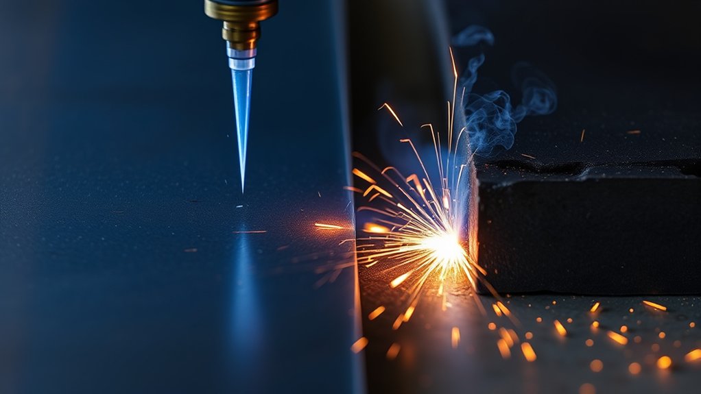
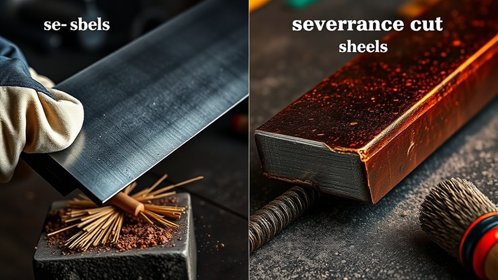
Clean Cut Vs Severance Cut: Key Definitions
Although both are plasma cuts, “clean cut” and “severance cut” describe very different performance levels at a specific amperage and thickness.
A clean cut gives you a smooth edge finish and minimal dross. You achieve this when your cutting techniques match the machine’s ideal operating window. For many 40 A units, this means cutting materials around 1/4 to 3/8 inch thick. You will use higher travel speeds, maintain a stable arc, and minimize extra grinding later. This level of quality is necessary when you need exact dimensions and a good-looking finish.
A severance cut happens when you push the machine to its maximum capacity. On a 40-amp machine, this often means cutting metal up to 1 inch thick. Expect a rougher edge finish, heavy dross, slower travel speeds, and plenty of post-cut cleanup. Severance cuts are just about separating the metal, not making it look pretty.
You should classify your jobs based on the required finish. Use clean cuts for precision parts and visible surfaces. Save severance cuts for rough sizing and scrap breakdown. Knowing the difference helps you plan your settings, save your consumables, and reduce your overall fabrication time.
Recommended Thickness for 40 Amp Plasma Cutters
Your target clean cut capacity should be about 1/4 inch at 40 amps. You can typically sustain 20 to 40 inches per minute (IPM) with minimal dross if you control your standoff distance.
For a severance cut, your practical limit is near 1 inch. Understand that the edge will be very rough and will require plenty of grinding.
Use these limits as your process window to set parameters, plan your workflow, and manage consumable life.
Clean Cut Capacity
When tuning a 40-amp plasma cutter for quality, prioritize its clean cut capacity. This is typically up to 1/4 inch mild steel. You get smooth edges and minimal dross at speeds roughly between 20 and 40 IPM.
Clean cuts offer great dimensional accuracy and a consistent kerf. Parts will drop free with almost no prying. This speeds up your work and reduces the need for heavy grinding before welding.
Keep your travel speed within the 20 to 40 IPM window. Set the amperage at 40 A, use the correct standoff distance, and supply dry, high-flow air to stop dross and edge beveling. These settings deliver repeatable, production-grade results on moderate thicknesses.
On the other hand, severance cuts force slower travel, rough edges, and significant cleanup. This slows down precision workflows. Choosing a machine rated for true 1/4-inch clean cuts maximizes your efficiency and reliability.
Severance Thickness Limit
Even with a 1/4-inch clean cut rating, a 40 A plasma cutter can usually sever material up to 1 inch thick. However, this comes at a steep cost to speed and quality.
During a severance cut, you must travel very slowly to maintain full penetration. Expect increased dross, a wider kerf, and a rough edge that demands heavy post-cut grinding. You will also see more edge taper and a higher risk of warping due to the massive heat input.
Plan for these plasma limitations. Use fresh consumables, maintain correct standoff, and angle the torch slightly forward to blow the molten metal clear.
Slow your speed down methodically until the arc pierces all the way through without failing. If you need production-grade results on plate thicker than 3/8 inch, you need a larger machine. A 40 A unit is only a backup tool at those thicker ranges. Match your machine capacity to your required finish.
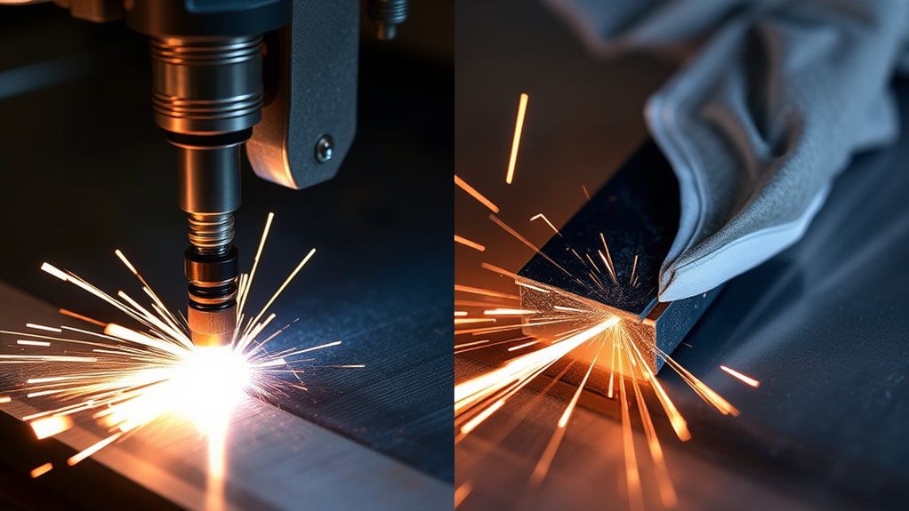
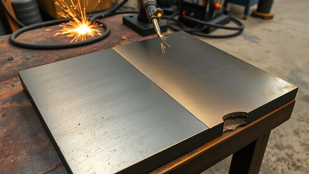
Cut Quality, Dross, and Post-Cut Cleanup
Cut quality depends entirely on amperage, thickness, and travel speed. A 40 A plasma cutter delivers clean cuts up to 1/4 inch and severance-quality cuts as you approach 1 inch. To get consistent results, you must use disciplined cutting techniques and follow strict maintenance practices.
Maintain the correct standoff. Use a drag shield or an automated height control to keep the arc stable, reduce edge bevel, and minimize dross.
On materials 1/4 inch or thinner, you will see smooth cut walls and light dross that easily flakes off with a chipping hammer or wire brush. As you approach severance thicknesses, expect uneven cuts, top spatter, and heavy dross that requires aggressive grinding.
Always verify your torch alignment, electrode condition, and gas flow. Worn consumables and poor airflow rapidly increase dross accumulation. Replace consumables before they fail completely, and inspect them after heavy cuts.
For efficient post-cut cleanup, follow a simple sequence. Knock off the heavy slag, use a wire brush, and finish with a flap disc only as needed to preserve the part’s dimensions.
Cutting Speed and Its Impact on Results
There is a direct relationship between your cutting speed and the final quality. At 40 A, traveling at 20 to 40 IPM usually produces clean kerfs. Slower travel immediately increases dross and edge taper.
You must respect thickness-driven speed limits. Reduce your speed as the material gets thicker to ensure full penetration.
Do not exceed the recommended speed. Moving too fast degrades the finish and burns up consumables. Moving too slow causes heavy dross buildup and heat distortion.
IPM Vs Cut Quality
When you set your cutting speed in inches per minute (IPM), you are balancing throughput and edge quality.
Higher IPM speeds typically produce cleaner edges and less dross on 40-amp systems. For example, moving at 20 IPM on 3/8-inch plate can yield a very solid clean cut.
Slowing down allows the arc to cut deeper, but pushes you toward severance territory. This causes a rougher kerf, more dross, and heat-affected taper.
Near the severance limit of 1 inch, you must drop your speed substantially to cut all the way through. You have to accept the downgraded finish.
Control your standoff precisely. Too low at high speed blows molten metal back onto the torch. Too high widens the kerf and weakens the arc. Balance IPM, standoff, and amperage to hit your target cut quality.
Thickness-Driven Speed Limits
While amperage sets your overall power, the material thickness decides your actual workable speed window. As metal gets thicker, you must slow down to maintain full penetration and keep the cut straight.
For clean cuts near the recommended thickness, target 20 to 40 IPM. This range maximizes your efficiency while keeping the edges clean and square. As you approach the machine’s severance limit, slow down to keep the arc from failing. Accept the rougher edges and longer cut times.
Exceeding the speed limit causes incomplete cuts, severe undercut, and massive dross. Moving too slow widens the kerf and warps the metal.
Always check the machine’s cut charts for specific alloys and thicknesses. Verify these settings on test coupons. Watch the arc lag, drag lines, and cut angle to confirm your speed is correct.
Dross at Slower Travel
As your travel speed drops, heat input skyrockets. This causes dross to increase rapidly, especially near severance thickness. Because you are pushing more heat into the cut, the molten metal solidifies on the bottom edge instead of blowing away cleanly.
Below the ideal 20 IPM window, cut quality drops fast. Edges get rough, bevels increase, and cleanup takes much longer. To achieve true dross reduction, hold a steady speed that matches the thickness. Do not slow down just to make the arc feel more stable.
- Verify your cut speed. Target around 20 IPM for clean cuts. Slower speeds create heavy dross.
- Monitor your arc lag angle. Increasing lag means you are moving too slow and adding too much heat.
- Optimize your standoff and air flow to keep the plasma jet tight.
- Check your edges. Measure the bevel and adjust your speed before you try increasing the amperage.
Selecting a Machine for Your Thickest Regular Material
Start by matching the machine’s clean-cut rating to the thickest metal you process regularly. Always add a little extra capacity for headroom.
Use material thickness as your primary guide. If you cut 1/4 inch plate every day, a unit rated for a 1/4 inch clean cut meets your basic needs. However, stepping up to a slightly larger machine preserves edge integrity at faster speeds and handles occasional severance tasks much better.
Understand the difference between clean cut vs severance ratings. A clean cut ensures repeatable edge quality and squareness. Severance is just an absolute upper limit. A 1/4 inch clean-cut machine can sever 1/2 inch metal, but it will be messy.
For general shop work, a 3/8 inch clean-cut class machine offers great balanced capacity. For heavier daily use, a 3/4 inch clean-cut class machine provides massive throughput and future-proofs your shop.
Buy the smallest machine that comfortably exceeds your daily thickness requirements. This keeps your quality high and your process stable.
Techniques: Drag Cutting, Standoff, and Ignition Types
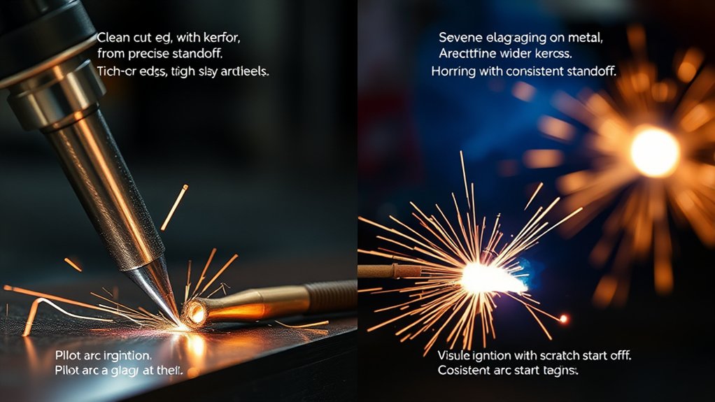
Even with the right machine capacity, your cutting technique determines the final result. For systems under 40 A, drag cutting is popular. It keeps the torch shield directly on the plate, stabilizes the arc, and reduces dross on thin metals.
Matched machine capacity is just the start. Technique locks in clean cuts on thin to mid-gauge metals.
Above 40 A, you must adopt a controlled standoff. This protects the nozzle, keeps the cut straight, and prevents the top edge from rounding over. Your choice of ignition methods also impacts reliability, especially on CNC tables.
- Set your mode by amperage. Use drag cutting for 40 A and below. Use a calibrated standoff above 40 A to save your nozzles.
- Control your stand-off to within ±0.5 mm using a height control system. Verify that your arc voltage matches the cut charts.
- Use Short Circuit starting on CNC tables to reduce electrical interference. Save High Frequency (HF) ignition for isolated, heavily shielded systems.
- Benchmark your quality by checking test coupons. Adjust your travel speed and standoff to hit your clean-cut targets.
Essential Safety Gear for Heavy Cuts
When pushing a 40-amp plasma cutter to its severance limit, you generate significantly more sparks, molten slag, and metal fumes than during thin sheet metal cuts. Always wear a shaded cutting shield or welding helmet (usually shade 5 for 40 amps) to protect your eyes from arc flash. Use heavy-duty leather gloves and a flame-resistant jacket to prevent burns from heavier dross blowback. Ensure your workspace is well-ventilated to clear the increased metal fumes, and always follow standard OSHA welding guidelines to keep your shop safe.
Plasma Vs Oxy-Fuel for Occasional Heavy Cuts
Both processes can cut thick plate. However, you will complete occasional heavy cuts much faster and cleaner with plasma. A 40 A system can sever up to 1 inch while holding tighter cuts and less dross than oxy-fuel.
You gain major plasma efficiency from higher travel speeds and consistent arc stability. Plasma requires no preheating, which improves edge quality and reduces post-cut grinding. You also avoid heavy gas cylinder handling. No gas bottles means lower consumable costs and zero flammable gas risks in the shop.
Oxy-fuel still has value on extremely thick stock and can deliver straighter edges on massive steel blocks. However, oxy-fuel limitations include slower cut rates, long preheat delays, massive slag generation, and a messier work zone.
For occasional heavy cuts near the 1-inch mark, a competent 40 A plasma inverter with dry air is usually faster and safer than firing up an oxy-fuel torch.
Frequently Asked Questions
What Gases Work Best With a 40A Cutter for Various Alloys?
Use clean air for carbon steel. Oxygen offers faster speeds if your torch is rated for it. Choose nitrogen for stainless steel and aluminum. Argon mixtures, like argon-hydrogen, greatly improve edge quality. Always verify your torch ratings and follow standard plasma cutting gas guidelines.
How Does Ambient Temperature Affect Cut Performance and Duty Cycle?
Ambient temperature completely changes machine performance. In high heat, your duty cycle drops rapidly, arc stability degrades, and you have to cut slower. In freezing weather, the duty cycle improves, but cables become stiff. Tune your amperage and gas flow based on the environment and the manufacturer specs.
Which Consumables Extend Tip Life at Near-Severance Thickness?
Use silver-alloy or hafnium-inserted tip materials paired with matched swirl rings. They resist extreme erosion during severance cuts. Extend your tip life by reducing cutting speed slightly, maintaining 65 to 75 psi of perfectly dry air, and strictly following the OEM amperage charts.
Can CNC Tables Improve Edge Squareness at 40 Amps?
Yes. You will drastically improve edge squareness with a CNC table. The machine perfectly stabilizes speed, standoff, and torch angle. Use automated height control, fine-cut consumables, and dry air. Expect measurable edge quality gains per ISO 9013 thermal cutting standards.
How Do Power Supply Voltage Drops Impact Cut Quality?
Voltage drops ruin cut quality by reducing arc stability and altering the arc length. This immediately causes heavy dross, edge taper, and micro-voids in the cut. You will notice slower speeds, an erratic kerf, and terrible repeatability. Always maintain a regulated power supply, keep your extension cords short, and monitor the voltage under heavy loads.
Conclusion
A 40 A plasma cutter gives you clean, low-dross cuts up to 1/4 inch thick. It can also push through severance cuts up to 1 inch thick, but requires heavy cleanup afterward. Always match your material thickness to your duty cycle, standoff distance, and travel speed. Choose a machine designed for the thickest material you cut daily, not the rare outlier job. If you dial in your process variables correctly, your cut quality will lock into repeatable, high-grade results every single time.