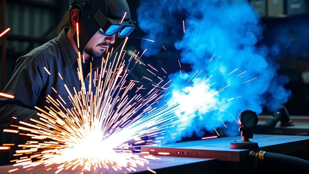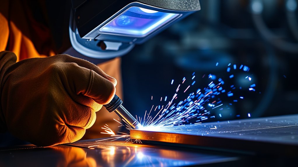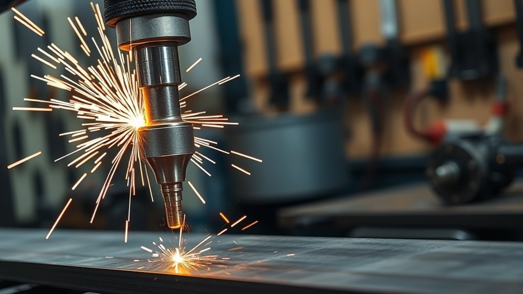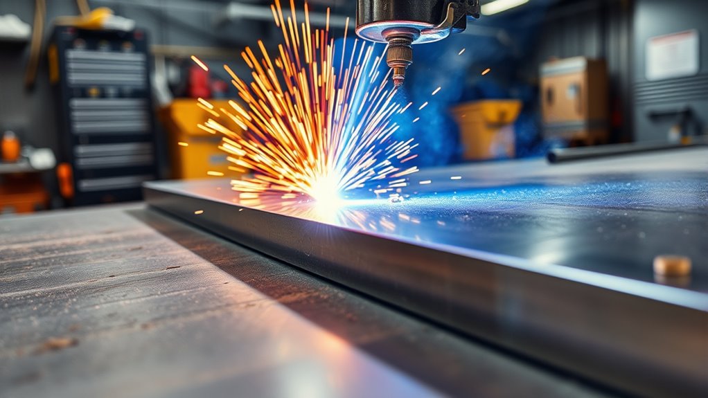
You can ruin a plasma cut quickly if the air supply drops, the work clamp has poor contact, or the torch moves at the wrong speed. Clean results start before you pull the trigger. This guide explains how to set up a handheld plasma cutter, protect yourself, make accurate cuts, care for consumables, and diagnose common problems.
Quick Answer
To use a plasma cutter, connect the correct input power and clean, dry air supply, install compatible consumables, and attach the work clamp to bare metal. Select the settings from your machine’s cut chart, wear full protective gear, and move the torch steadily while watching the arc pass through the metal.
Key Takeaways
- Match both air pressure and airflow in SCFM to the requirements in your plasma cutter manual.
- Attach the work clamp to clean, paint-free metal close to the cut, but do not confuse the work lead with protective earth.
- Use the correct shaded eye protection, safety glasses, gloves, fire-resistant clothing, sturdy footwear, and hearing protection.
- Identify paint, plating, galvanizing, and other coatings before cutting because heated coatings can release hazardous fumes.
- Use an edge start when possible, and follow the manufacturer’s piercing method when the cut must start in the middle of the plate.
- Inspect the electrode, nozzle, shield, retaining cap, and air supply when cut quality changes.
At a Glance
| Time Required | About 15–45 minutes for setup, layout, and a simple cut |
| Difficulty | Beginner to intermediate; practice on matching scrap metal first |
| Tools Needed | Plasma cutter, approved input power, suitable air supply, compatible consumables, work lead, layout tools, PPE, ventilation, and fire extinguisher |
| Cost | Varies; when the equipment is already owned, the main costs are electricity, compressed air, and consumable wear |
What’s in This Article
- Understanding the Plasma Cutting Process
- Before You Begin Plasma Cutting
- Essential Equipment and Setup for Plasma Cutting
- Safety Protocols and Protective Gear
- Step-by-Step Plasma Cutting Process
- Techniques for Achieving Precision Cuts
- Maintenance and Replacement of Consumables
- Troubleshooting Common Plasma Cutting Issues
- Frequently Asked Questions
- Conclusion
- Sources
Understanding the Plasma Cutting Process
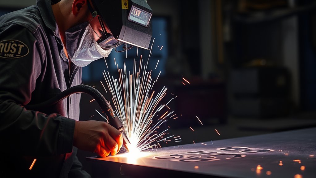
Plasma cutting uses an electric arc and a fast stream of ionized gas to melt and remove metal. It works on electrically conductive materials such as mild steel, stainless steel, aluminum, copper, and brass. The machine must still have enough output for the type and thickness of metal you plan to cut.
In many modern handheld systems, a low-energy pilot arc first forms between the electrode and nozzle inside the torch. When the torch is close enough to a workpiece connected to the work lead, the arc transfers to the metal and becomes the cutting arc.
The pilot arc prepares a conductive path; the transferred arc between the electrode and workpiece performs the cut.
The nozzle constricts the arc into a narrow, high-energy stream. That stream melts the metal, while the cutting gas blows molten material out of the kerf. The kerf is the narrow slot left by the cut.
Plasma normally does not require the preheating used in routine oxy-fuel cutting. This allows quick starts and makes plasma useful for sheet metal, repairs, fabrication, artwork, and cutting nonferrous metals that oxy-fuel equipment cannot cut in the same way.
Cut quality depends on the full setup: amperage, cutting mode, air quality, gas flow, torch height, consumable condition, material thickness, and travel speed. The cut chart in your operator manual should control these settings because there is no universal amperage or pressure chart for every machine.
Before You Begin Plasma Cutting
A simple cut may take only seconds, but safe setup and accurate layout often take 10 to 30 minutes. Identify the material, inspect the machine, confirm the air and electrical supply, and remove hazards before you strike an arc.
What You’ll Need
- Plasma cutter with the correct input voltage, plug, circuit capacity, and cutting capacity
- Clean, dry, oil-free compressed air or the cutting gas required by the manufacturer
- Air compressor that meets the required pressure and SCFM while air is flowing
- Filter, water separator, or dryer when the air supply contains moisture or contamination
- Work lead and a clean, bare-metal contact point
- Electrode, nozzle, shield, retaining cap, swirl ring, or cartridge made for the torch and amperage
- Marker, soapstone, straightedge, template, or cutting guide
- Safety glasses with side protection and suitable shaded eye and face protection
- Dry welding gloves, fire-resistant clothing, sturdy leather footwear, and hearing protection
- Local exhaust or other ventilation appropriate for the metal and coating
- A suitable fire extinguisher and a clear, noncombustible cutting area
Warning: Plasma cutting creates intense light, ultraviolet and infrared radiation, hot sparks, molten slag, fumes, noise, and dangerous electrical voltage. Never operate a cutter without reading its manual and using the required protection.
Identify the Metal and Any Coating
Confirm what the workpiece is made from before cutting. Mild steel, stainless steel, aluminum, copper, cast iron, and plated or coated metals can behave differently and may need different settings or ventilation controls.
Paint, galvanizing, plating, primers, grease, sealants, and preservative coatings can produce hazardous fumes when heated. Lead-, cadmium-, chromium-, nickel-, zinc-, and beryllium-containing materials require special care. Do not cut a coating you cannot identify or control safely.
Remove rust, paint, oil, and dirt from the work-clamp contact point. Cleaning that small area improves electrical contact, but it does not make the fumes from the remaining coating safe.
Warning: Never cut a sealed container, pressurized vessel, fuel tank, drum, cylinder, pipe, or other container unless it has been properly cleaned, opened, tested, and approved for hot work by a qualified person.
Check Input Power and Duty Cycle
Confirm the machine’s voltage, phase, input-current requirement, plug, breaker, and grounding instructions. Some portable cutters can use more than one voltage, but their output and duty cycle may change with the supply voltage.
Duty cycle is the amount of cutting time allowed within a stated period before the machine must cool. For example, a 20% duty cycle based on a 10-minute period means two minutes of rated cutting followed by eight minutes of cooling under the specified test conditions.
Use only extension cords, generators, plugs, adapters, and branch circuits allowed by the manufacturer. An undersized cord can cause voltage drop, poor performance, overheating, or nuisance breaker trips. Do not replace a breaker with a larger one to force the cutter to run. Have uncertain electrical service checked by a qualified electrician.
Essential Equipment and Setup for Plasma Cutting
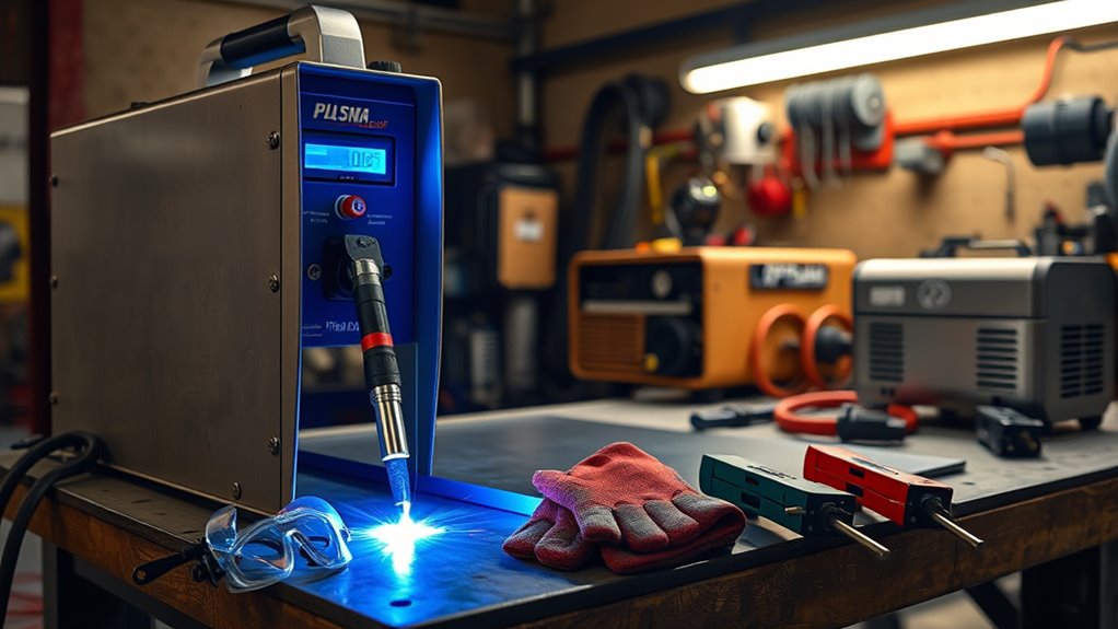
Set the plasma cutter on a stable, dry surface with clear airflow around its cooling vents. Inspect the torch cable, power cord, air hose, fittings, work lead, and machine case before connecting power.
Install only the consumables specified for your torch, amperage, and cutting mode. A nozzle made for one current range may not perform correctly at another setting. Make sure every part is seated in the proper order and that the retaining cap is secure.
Products Worth Considering

Package Include: 10 Shield Cups, 50 Nozzles, 20 Swirl Baffle, and 30 Electrodes.

[Achieve Precise Cuts] PT31 Plasma Cutting Consumables – Your Essential Tool for Efficient Cutting! Whether you're working with sheet metal, steel, or any other material, superior cutting performance ensure clean, accurate, and smooth cuts.

High-Quality Material:Made of high quality material to ensure a longer lifespan and superior performance.
Key Plasma Cutter Components
The power supply converts incoming electricity into the DC output used for the cutting arc. The torch holds the electrode, nozzle, shield, swirl ring, and other consumable parts that create and shape the plasma stream.
The air or gas system supplies the cutting gas, cools torch parts, and blows molten metal from the kerf. The work lead connects the workpiece to the cutting-current return circuit.
The work lead is often casually called a ground cable, but it is not the same as the protective-earth conductor in the machine’s input-power system. Both connections must be correct for their separate purposes.
Note: Attach the work clamp to clean, paint-free metal close to the cut and on the section that will remain connected throughout the cut. Do not place it on a small offcut that will fall away.
Proper Air Compressor Setup
Check two air-supply numbers in the operator manual:
- Pressure: The PSI or bar required at the cutter inlet.
- Flow: The cubic feet per minute, or SCFM, the compressor must deliver at that pressure.
A compressor can show adequate pressure while idle and still lose too much pressure after the torch begins flowing air. Check the regulator while the machine is in its air-test or purge mode when the manual instructs you to do so.
Tank volume alone does not determine whether a compressor will run a plasma cutter. A 20-gallon tank may work with one cutter and fall behind another. The compressor’s delivered SCFM, recovery rate, duty cycle, hose size, and pressure drop matter more than tank capacity by itself.
Use clean, dry air and keep oil out of the cutting-gas line unless the plasma-cutter manufacturer specifically requires another arrangement. Do not connect the cutter downstream from an airline lubricator. Drain the compressor tank, inspect the filter, and replace wet or contaminated filter elements.
Use a hose and fittings large enough to deliver the required flow. Kinked hoses, undersized quick couplers, leaks, and long narrow lines can cause pressure loss and rough cuts.
Essential Safety Gear
- Protect your eyes and face: Wear safety glasses with side protection under an approved cutting shield, goggles, or helmet with the correct filter shade. Follow the machine manual and workplace hazard assessment.
- Cover exposed skin: Wear dry, hole-free welding gloves and fire-resistant clothing that covers your arms, neck, and legs. Avoid synthetic fabric that can melt.
- Protect your feet: Wear sturdy leather footwear or safety boots. Keep trouser cuffs over the boot tops so sparks cannot fall inside.
- Protect your hearing: Use earplugs or earmuffs when required. Ear protection also helps keep sparks out of the ear canal.
- Control fumes: Keep your head out of the fume plume and use suitable local exhaust or mechanical ventilation.
Safety Protocols and Protective Gear
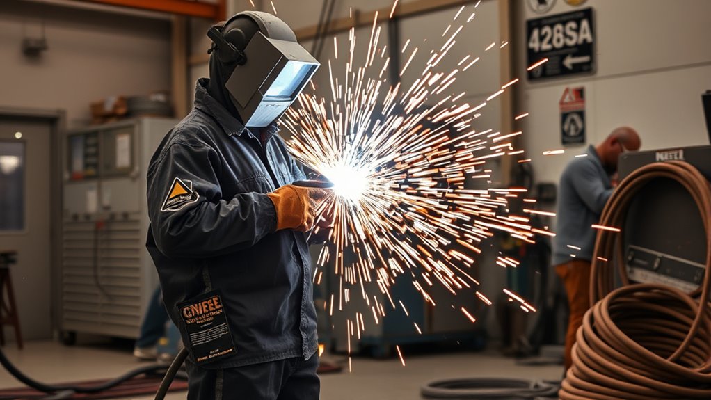
Plasma cutting combines arc-cutting, hot-work, electrical, respiratory, and noise hazards. Treat the work area as a hot-work zone before making the first cut.
Products Worth Considering

Impact resistant helmet with 6 ventilation holes for high breathability

【Professional Welding Safety Goggles】Made of high quality PC + ABS material, features anti-ultraviolet, infrared radiation, anti-glare, which can resist 99% of the harmful light to the eyes.

Detachable Design: Our welding helmet offers the convenience of a separable design where the face shield and the welding goggles can be detached, ensuring an easier and more comfortable use for welders.
Eye, Face, and Skin Protection
The bright arc can injure unprotected eyes and skin. OSHA lists shade 8 as the minimum protective filter for light plasma arc cutting below 300 amps, but your equipment manual or workplace assessment may call for a darker shade. Start with a shade that is too dark to see the cut clearly, then move to a lighter shade without going below the required minimum.
Use safety glasses with side protection for flying particles even when a helmet or shield covers your face. Protect nearby people with suitable screens and make sure they do not watch the arc without proper eye protection.
Fume and Ventilation Safety
Cutting fumes depend on the base metal, coating, surface contamination, cutting gas, and process settings. General room airflow may not be enough. Position local exhaust close enough to capture fumes without disturbing the cutting stream.
Stainless steel, galvanized metal, plated parts, and metal coated with lead-, cadmium-, chromium-, nickel-, or zinc-containing materials may create more hazardous fumes than clean mild steel. Follow applicable workplace exposure rules and respiratory-protection requirements.
Do not use chlorinated cleaners or solvents near the arc. Remove oil and degreaser residue with a product approved for hot work, and allow the workpiece to dry fully before cutting.
Fire and Explosion Prevention
Remove paper, cardboard, sawdust, fuel, solvents, aerosols, gas cylinders, and other combustibles from the cutting area. Remember that sparks and slag can travel through cracks, floor openings, wall penetrations, and gaps under the workpiece.
Keep a suitable fire extinguisher nearby. Check both sides of walls, floors, and partitions when hot material can pass through them. Use a fire watch when sparks may reach hidden or difficult-to-monitor areas, and inspect the area again after cutting.
Do not support the workpiece on a closed drum or container. Hot slag can collect inside, ignite residue, or create pressure.
Electrical Safety
Keep the machine, gloves, clothing, torch, cables, and work area dry. Do not cut while standing in water or while touching the workpiece with bare skin. Never touch the torch tip, electrode, workpiece, or cutting circuit while the output is energized.
Turn off and disconnect input power before changing consumables or opening any permitted service area. Allow capacitors to discharge for the period stated in the manual. Internal electrical repair and removal of outer covers should be left to qualified technicians.
Do not bypass a torch safety interlock, damaged retaining cap, breaker, fuse, protective-earth connection, or other safety device.
Step-by-Step Plasma Cutting Process
Use the same setup order each time. A repeatable process reduces missed safety checks and makes cut-quality problems easier to diagnose.
- Read the machine manual: Confirm input power, air pressure, airflow, duty cycle, consumable stack, cutting capacity, filter shade, and cut-chart settings.
- Identify the material: Confirm the metal, thickness, coating, plating, and surface contamination. Do not continue when the material or coating presents an uncontrolled fume or explosion hazard.
- Prepare the work area: Remove combustibles, arrange ventilation, place the metal on a stable noncombustible support, and provide a path for sparks and slag.
- Put on protective equipment: Wear safety glasses, suitable shaded face and eye protection, welding gloves, fire-resistant clothing, sturdy footwear, and hearing protection.
- Disconnect power and inspect the torch: Check the electrode, nozzle, shield, retaining cap, swirl ring, cartridge, and O-rings. Install the correct parts in the proper order.
- Connect the air supply: Use clean, dry air or the gas required by the manufacturer. Set the regulator and confirm adequate flow in the machine’s test or purge mode.
- Connect input power: Use the approved outlet, circuit, plug, extension cord, or generator. Confirm that the machine is set for the available supply when manual voltage selection is required.
- Attach the work lead: Clamp it to clean bare metal near the cut and on the portion of the workpiece that will remain connected.
- Mark the cut: Use a marker, soapstone, straightedge, circle guide, or template. Allow for the width of the kerf when part dimensions matter.
- Select the cutting mode and amperage: Use the manufacturer’s cut chart for the material, thickness, consumables, and desired cut quality. Do not exceed the nozzle or cartridge rating.
- Position the torch: Hold a drag-compatible shield on the plate only when the torch is designed for drag cutting. Otherwise, maintain the specified standoff distance.
- Start the arc: Use an edge start when possible. Center the nozzle over the edge, start the arc, and pause until it passes fully through the metal.
- Pierce correctly when required: Follow the manual. On thicker material, a rolling pierce often begins with the torch tilted so molten metal blows away from the nozzle, followed by rotating the torch upright after penetration.
- Move at a steady speed: Keep the torch close to 90 degrees for a square cut and watch the sparks exit through the bottom of the plate. Adjust speed within the cut-chart guidance when the arc trails excessively or fails to penetrate.
- Finish and shut down safely: Release the trigger as directed, allow postflow to cool the torch, switch off the machine, and disconnect power before service. Let the workpiece and slag cool before handling them.
Pro Tip: Make a test cut on scrap metal of the same type and thickness. Check the edge, dross, kerf, and arc behavior before cutting the final part.
Techniques for Achieving Precision Cuts
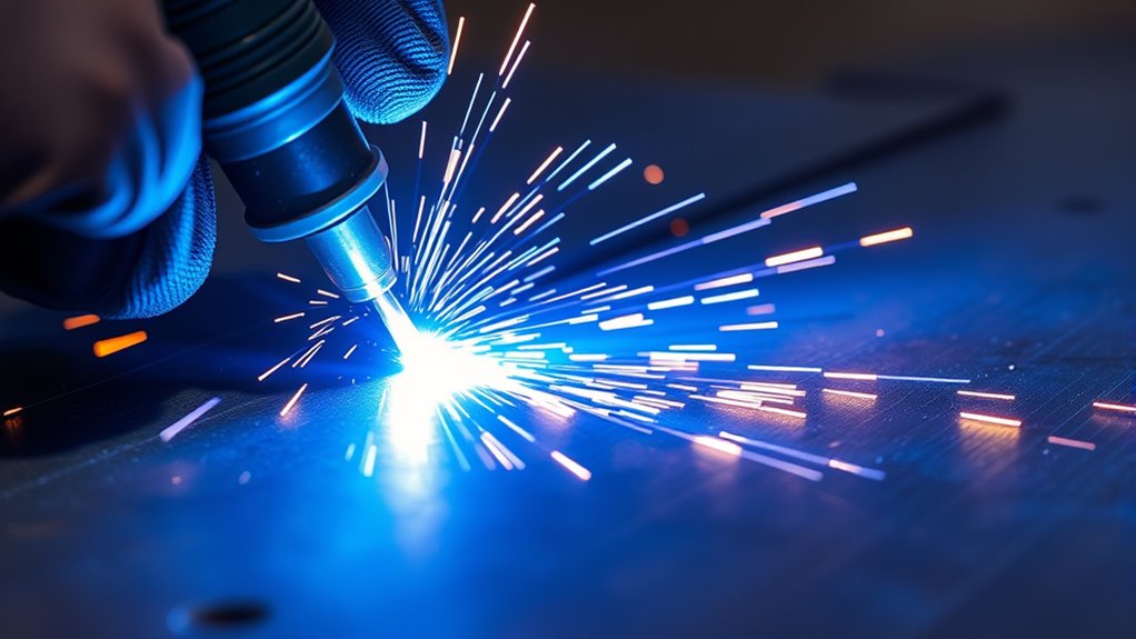
Clean plasma cuts require consistent torch height, angle, speed, and electrical contact. Hold the torch close to 90 degrees to the plate for a square edge unless you are intentionally piercing, beveling, or gouging.
A steady torch is important, but the correct speed and standoff matter just as much as a steady hand.
Drag Cutting Versus Standoff Cutting
A drag shield is designed to slide lightly on the workpiece while keeping the nozzle at the intended distance. It can make freehand cutting easier. An exposed or non-shielded nozzle may require a small air gap instead.
Do not drag a nozzle that is not designed for contact with the plate. Direct contact can damage the nozzle, disturb the arc, and shorten consumable life. Follow the torch manual rather than assuming every handheld torch is drag compatible.
Control Cutting Speed
When speed is close to correct, the arc passes through the plate and the sparks leave the bottom of the cut. Sparks spraying back toward the top often indicate excessive speed, insufficient output, too much standoff, or worn consumables.
Moving too slowly can widen the kerf, increase heat input, create a rounded top edge, and leave thick low-speed dross. Moving too quickly can leave an incomplete cut or a small, hard bead of high-speed dross.
Use Guides and Allow for Kerf
Use a straightedge, template, circle guide, or purpose-made torch guide when dimensions matter. Measure the distance from the torch centerline to the guide edge before positioning the guide.
Place the torch on the waste side of the marked line so the kerf does not remove material from the finished part. Make a test cut and measure the actual kerf when close tolerances are required.
Consider Cut Direction
The gas swirl inside a plasma torch often produces one edge that is squarer than the other. Many torches place the better edge on a predictable side of the direction of travel, but the preferred direction can vary by torch design and whether you are cutting an outside profile or an inside hole.
Follow the manufacturer’s direction guidance and test on scrap before cutting a finished part. Keep the desired finished edge on the correct side of the torch path.
Material-Specific Expectations
| Material | What to Expect | Main Check |
| Mild steel | Usually the easiest material for judging travel speed and dross | Use the cut chart for thickness and consumable size |
| Stainless steel | Edge color and dross may differ from mild steel | Control chromium- and nickel-containing fumes |
| Aluminum | The edge and dross may look rougher than a steel cut at similar thickness | Use the aluminum settings and capacity in the manual |
| Painted, plated, or galvanized metal | The arc may cut it, but the coating can contaminate the cut and create hazardous fumes | Identify the coating and use appropriate controls before heating it |
Maintenance and Replacement of Consumables
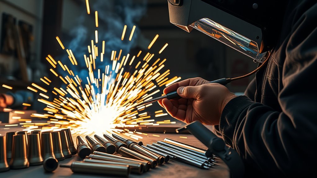
Consumables shape and control the arc. Worn, damaged, contaminated, or incorrectly assembled parts can cause hard starts, excess bevel, a wider kerf, incomplete cuts, and short torch life.
Turn off and disconnect the cutter before removing torch parts. Let the torch cool, and follow any waiting period stated in the manual.
Consumable Lifespan Considerations
Consumable life depends on amperage, nozzle rating, air quality, material thickness, pierce height, torch-to-work distance, number of starts, cutting speed, and postflow cooling.
Use these habits to extend service life:
- Use the correct parts: Match every component or cartridge to the torch, cutting mode, and current range.
- Avoid unnecessary pilot-arc starts: Firing the torch without cutting wears the electrode and nozzle.
- Prefer edge starts: Edge starting normally exposes the front of the torch to less molten blowback than piercing.
- Keep the air clean: Drain moisture, inspect filters, and prevent oil from entering the gas line.
- Respect postflow: Allow the cooling-air cycle to finish before switching off the machine when required by the manual.
- Track performance: Record the material, amperage, number of starts, and signs of wear when diagnosing short life.
Identifying Worn Components
- Electrode: Replace it when the emitting tip is deeply eroded, damaged, loose, or beyond the wear limit in the manual.
- Nozzle: The opening should remain round and centered. Replace a nozzle with an enlarged, oval, nicked, or burned orifice.
- Shield or drag shield: Replace it when cracked, heavily scorched, blocked with spatter, or unable to maintain the proper spacing.
- Swirl ring: Inspect for cracks, blocked passages, burns, or distortion that can disturb gas flow.
- Retaining cap: Check its threads, seating surfaces, air holes, and parts-in-place function.
- O-rings: Replace cut, flattened, swollen, or cracked seals. Use only the lubricant and amount specified by the manufacturer.
Do not replace only the nozzle automatically. A damaged electrode can quickly damage a new nozzle, and a blocked swirl ring can make several new parts appear defective.
Optimizing Consumable Performance
- Inspect before each session: Look for contamination, loose parts, damaged seals, and blocked gas passages.
- Install parts clean and dry: Keep metal dust, grinding debris, grease, and moisture away from the inside of the torch.
- Use the correct amperage: Do not exceed the rating of the installed nozzle or cartridge.
- Control pierce height and angle: Keep molten blowback away from the nozzle and shield.
- Maintain the work connection: Poor electrical contact can cause unstable transfer and inconsistent cutting.
- Store spares properly: Keep compatible electrodes, nozzles, shields, seals, and cartridges in clean, labeled containers.
Pro Tip: When cut quality changes suddenly, compare the entire consumable stack with a known-good set rather than changing random parts one at a time.
Troubleshooting Common Plasma Cutting Issues

Start with the simple checks: input power, error lights, torch assembly, air flow, work-clamp contact, cutting mode, amperage, standoff, speed, and consumable condition. Change one variable at a time so you can identify the real cause.
Most handheld plasma-cutting problems can be narrowed down by checking power, air, consumables, the work connection, torch position, and travel speed in that order.
| Problem | Likely Causes | What to Check |
| Torch does not fire | No input power, open interlock, incorrect torch assembly, low air flow, or machine fault | Breaker, plug, indicators, retaining cap, consumable order, air-test result, and manual fault code |
| Pilot arc starts but does not transfer | Poor work-clamp contact, clamp on the falling offcut, excessive torch distance, or contaminated surface | Clamp to clean bare metal on the retained section and move the torch within the specified transfer distance |
| Incomplete cut | Travel too fast, amperage too low, plate beyond capacity, excessive standoff, low air flow, or worn nozzle | Cut chart, actual thickness, delivered air flow, speed, torch height, and consumables |
| Thick, bubbly bottom dross | Travel too slow, excessive amperage, standoff too low, or heat buildup | Increase speed in small steps, verify amperage, and restore the specified standoff |
| Small, hard bottom bead | Travel too fast, amperage too low, standoff too high, or worn nozzle | Reduce speed in small steps, check the nozzle, and confirm the cut-chart setting |
| Heavy bevel or uneven edge | Torch tilted, inconsistent standoff, wrong direction, damaged nozzle, or speed outside the clean-cut range | Hold the torch square, use a guide, inspect the nozzle, and test the direction of travel |
| Sputtering or unstable arc | Moisture, oil, pressure drop, air leak, loose consumables, or poor work contact | Drain the compressor, inspect filters and hoses, test flowing pressure, and reseat the consumables |
| Consumables fail quickly | Wrong parts, excessive current, wet air, unnecessary starts, poor piercing technique, or interrupted postflow | Part numbers, nozzle rating, air quality, pierce method, start count, and cooling cycle |
| Breaker trips or cord overheats | Undersized circuit or extension cord, incorrect voltage setup, damaged equipment, or internal fault | Stop cutting, disconnect power, and have the supply and machine checked by a qualified person |
Dross is re-solidified molten metal that was not fully blown out of the kerf. Speed, amperage, standoff, material condition, air flow, and consumable wear can all affect it. Do not assume every dross problem means you should slow down.
Note: Stop using the cutter if it repeatedly trips breakers, displays an electrical fault, has damaged insulation, leaks air inside the case, or produces smoke or a burning smell. Do not remove the outer cover unless you are qualified and the manufacturer’s service procedure permits it.
Frequently Asked Questions
What are some common mistakes made with plasma cutting?
Common mistakes include using wet or oily air, ignoring the required SCFM, installing mismatched consumables, attaching the work clamp to painted metal, using the wrong amperage, dragging an exposed nozzle, piercing too close to the plate, and moving too fast or too slowly. A test cut on matching scrap can reveal most setup problems.
Will a 20-gallon air compressor run a plasma cutter?
It may run some plasma cutters, but tank volume alone does not answer the question. Compare the compressor’s delivered SCFM at the required PSI with the cutter’s specification. Also consider pressure drop, hose size, compressor recovery time, and how long you plan to cut continuously.
What do 2T and 4T mean on a plasma cutter?
On many cutters, 2T requires you to hold the trigger while cutting. In 4T mode, one trigger action starts the cutting cycle and a later action ends it, reducing hand strain during long cuts. Trigger logic varies, so confirm the exact sequence in your machine manual before using 4T.
What PSI should I run my plasma cutter at?
Use the inlet pressure specified for your exact machine and check it using the procedure in the manual. Do not rely on a universal PSI number. The compressor must also deliver the required SCFM at that pressure while the torch is flowing air.
Why does my plasma cutter leave so much dross?
Heavy dross can come from incorrect speed, amperage, standoff, air flow, consumable wear, or material condition. Thick, bubbly dross often points to slow travel or too much heat. A small, hard bead often points to fast travel, low output, excessive standoff, or a worn nozzle.
Can you plasma cut painted or rusty metal?
A plasma arc can often cut through rust or paint, but the work clamp needs clean bare-metal contact. More importantly, heated coatings may release hazardous fumes. Identify the coating, remove it safely where appropriate, and use the ventilation or respiratory controls required for that material. Do not cut an unknown coating.
Can a plasma cutter cut aluminum and stainless steel?
Yes. Plasma can cut electrically conductive metals, including aluminum and stainless steel, when the cutter has enough capacity. Use the material-specific settings and consumables in the manual, and provide suitable fume controls, especially when cutting stainless steel or coated material.
Should I drag the plasma-cutter tip on the metal?
Drag the torch only when it has a shield or consumable designed for drag cutting. Other nozzle styles require a specified standoff distance. Dragging an exposed nozzle can damage it and disturb the arc, so check the torch manual before allowing any part of the tip to contact the plate.
Conclusion
Clean plasma cuts begin with a safe, machine-specific setup. Confirm the electrical supply, match both air pressure and SCFM, install the correct consumables, and attach the work clamp to bare metal. Identify hazardous coatings, control fumes and sparks, and wear complete protective gear.
During the cut, keep the torch at the correct angle and standoff, use an edge start when possible, and adjust travel speed based on the arc and finished edge. When quality changes, inspect power, air, the work connection, torch position, and the complete consumable stack before replacing parts at random.
Sources
- OSHA: Welding, Cutting, and Brazing—Hazards and Solutions — supports the discussion of fumes, radiation, burns, electrical shock, and PPE.
- OSHA 29 CFR 1910.133: Eye and Face Protection — provides minimum filter-shade guidance for plasma arc cutting.
- OSHA 29 CFR 1926.353: Ventilation and Protection in Welding, Cutting, and Heating — supports ventilation and toxic-metal precautions.
- Hypertherm: How to Plasma Cut — supports work-clamp placement, edge starting, piercing, amperage selection, and steady torch movement.
- Hypertherm: 10 Common Plasma Arc Cutting Mistakes — supports air-quality, consumable, standoff, piercing, and travel-speed guidance.
- Hypertherm: Troubleshooting Too Much Dross — supports the low-speed and high-speed dross guidance.