Plasma Tip Size Chart: Amperage, Air Pressure, and Kerf Guide
What’s in This Article
- How Tip Orifice Size Relates to Amperage and Kerf
- Recommended Tip Sizes, Amperage, and Air Pressure
- Matching Metal Thickness to Amperage and Travel Speed
- Pierce Height, Standoff, and Voltage for Clean Cuts
- Kerf Compensation and Cut Path Offsets
- Brand Differences: Using Charts Across Plasma Cutters
- Quick Reference Charts for Steel, Stainless, and Aluminum
- Frequently Asked Questions
A plasma tip chart helps you avoid wide kerfs, heavy dross, and burned consumables. You need to match plasma tip orifice, amperage, air pressure, metal thickness, and travel speed before you start cutting. This guide gives you practical baseline settings, plus simple checks for standoff, pierce height, and cut quality.
Quick Answer
Match the plasma tip size to the amperage range first, then adjust air pressure and travel speed with a test cut. A smaller orifice gives you a narrower kerf on thin metal, while a larger orifice handles higher current and thicker stock. Always confirm the final setting with your machine manual and a short test coupon.
Key Takeaways
- Choose the tip orifice by amperage before you adjust speed or pressure.
- Use clean, dry air to protect the nozzle and improve arc stability.
- Set pierce height higher than cutting height to reduce blowback damage.
- Measure the real kerf on scrap before you update your cut path offset.
- Use your machine’s manual as the final setting guide for your torch and consumables.
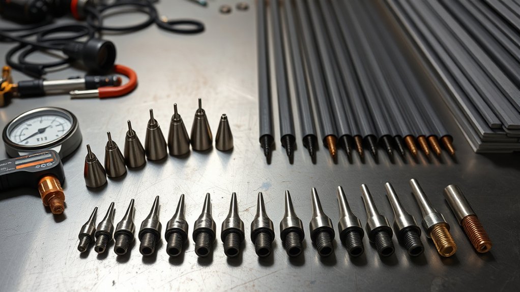
How Tip Orifice Size Relates to Amperage and Kerf
Precision starts at the orifice. You control arc energy when you match tip diameter to output current. A small tip focuses the arc for thin stock, while a larger tip supports higher current for thicker metal.
Match tip diameter to current so you can control arc energy and kerf width.
As a baseline, a 0.6 mm tip often works well in the 15–20 amp range for thin metal. A 1.0 mm tip often supports the 41–50 amp range when the machine and consumables allow it. This match helps the plasma jet stay focused and stable.
Kerf follows the orifice, but it does not match it exactly. The finished cut often runs slightly wider than the orifice because arc flare and heat remove more material.
Your travel speed also changes kerf width. If you move too slowly, the kerf grows and dross builds up. If you keep the speed steady, you get a narrow, consistent kerf and reduce waste.
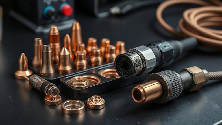
Products Worth Considering

10 pcs TIPS (Extended) /10 pcs ELECTRODE (Extended) /10 pcs SHIEDED-CUP/10 pcs GAS RING

High-Quality Material:Made of high quality material to ensure a longer lifespan and superior performance.

fits S25, S25K, S30, S35, S45 found on Chicago Electric 95539 95413 60767 95136 97994 torch
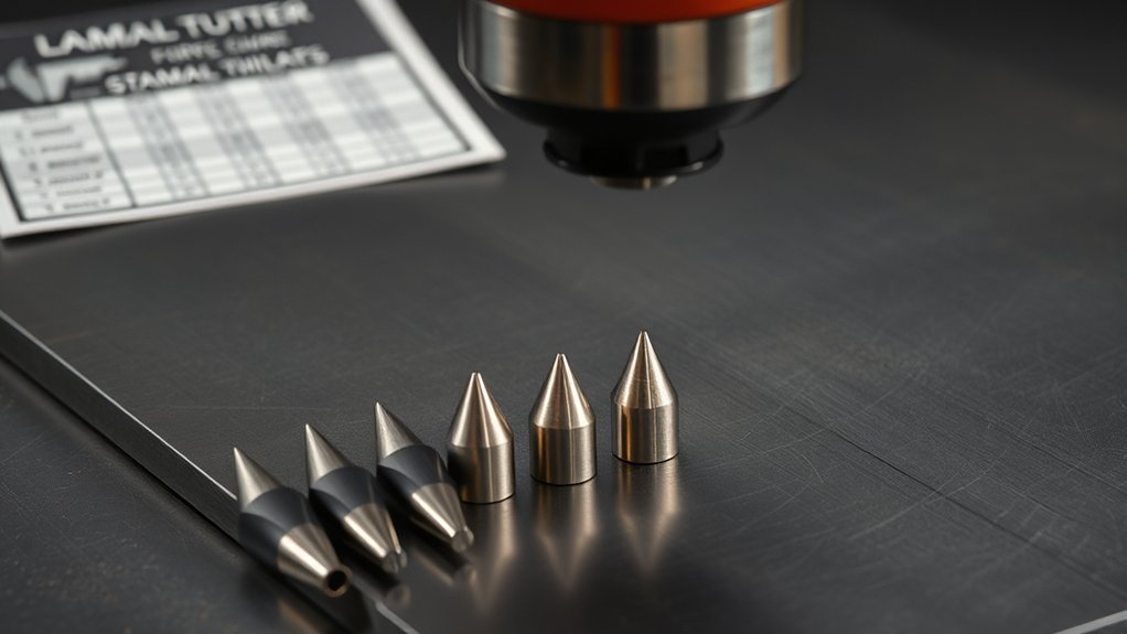
Recommended Tip Sizes, Amperage, and Air Pressure
Start with the machine’s chart, then dial in the result on scrap metal. Match the tip orifice to output current and set air pressure inside the recommended range. Watch the cut face, top spatter, and dross as you make small changes.
Use these baseline ranges when your torch and manual support them:
- 20A tip (0.6 mm/.025): 15–20 A, 50–55 psi
- 30A tip (0.8 mm/.030): 21–30 A, 55–60 psi
- 40A tip (0.9 mm/.035): 31–40 A, 65–70 psi
- 50A tip (1.0 mm/.040): 41–50 A, 65–75 psi
- 60A tip (1.1 mm/.044): 51–60 A, 65–75 psi
| Tip (A) | Current Window (A) | Air Pressure (psi) |
|---|---|---|
| 20 | 15–20 | 50–55 |
| 30 | 21–30 | 55–60 |
| 40 | 31–40 | 65–70 |
| 50 | 41–50 | 65–75 |
| 60 | 51–60 | 65–75 |
Set amperage first so you stay within the nozzle’s heat limit. Then adjust pressure 2–3 psi at a time. Low pressure weakens arc focus, while too much pressure can widen the kerf and wear the tip faster.
Warning: Do not exceed the tip’s rated amperage, because excess heat can damage the nozzle and cause poor cuts.
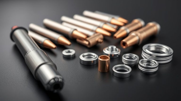
Products Worth Considering

Package list : Plasma torch S45 tips kit

Package list : Plasma torch S45 tips kit

[Achieve Precise Cuts] PT31 Plasma Cutting Consumables – Your Essential Tool for Efficient Cutting! Whether you're working with sheet metal, steel, or any other material, superior cutting performance ensure clean, accurate, and smooth cuts.
Matching Metal Thickness to Amperage and Travel Speed
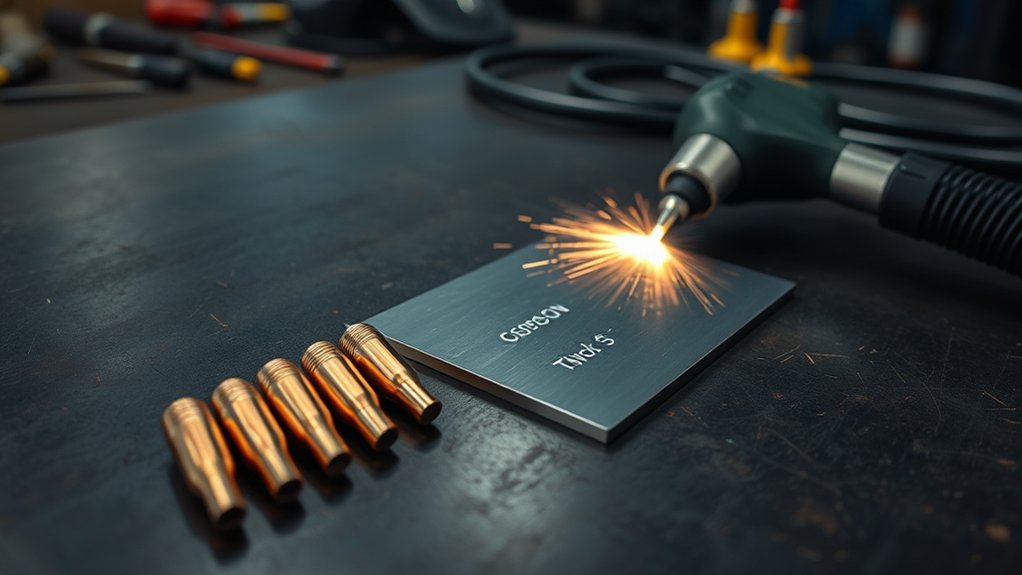
Two settings drive clean plasma cuts: amperage matched to thickness and travel speed matched to heat input. You need enough power to sever the metal without overheating the edge.
For manual cutting, many operators start near 20 amps for thin 1/8 inch stock, then add current as thickness increases. For example, 1/4 inch mild steel may need about 40–50 amps on many small plasma cutters.
For computer numerical control (CNC) cutting, steady motion and controlled torch height can support lower heat input in some setups. Always check your machine chart because CNC speed, torch style, and consumables change the final setting.
Coordinate travel speed with heat input. Manual cutting often moves slower than automated cutting, while CNC motion can move much faster on thin material. Your goal is a clean spark stream that exits through the bottom of the cut.
If you move too slowly, you overheat the edge, widen the kerf, and create dross. If you move too fast, the cut may leave unsevered sections or an uneven kerf.
Adjust travel speed in small steps. Keep the arc trailing slightly behind the leading edge of the kerf. Then check cut face uniformity, kerf width, and complete separation.
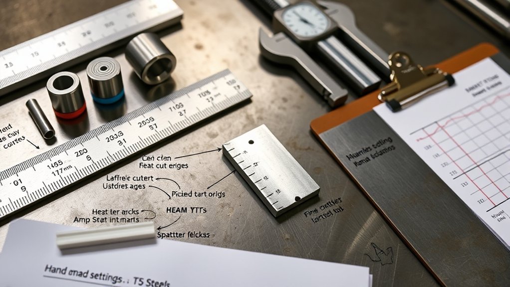
Pierce Height, Standoff, and Voltage for Clean Cuts
Amperage and speed set the heat level, but pierce height, standoff, and arc voltage shape the final cut. Set pierce height higher than cutting height to protect the nozzle from blowback. Many setups use pierce height at about 1.5–2 times cutting height, but your manual should set the final value.
After piercing, drop the torch to the correct cutting height before motion. Keep a steady standoff with torch height control when your machine has it. Height changes can increase bevel, widen the kerf, and reduce part accuracy.
Tune arc voltage to hold the target height on CNC systems. Higher voltage usually raises the torch, while lower voltage brings it closer to the work. Too much change in either direction can increase dross or angularity.
- Confirm sparks trail behind the torch during a good cut.
- Use a test coupon to check bevel symmetry and dross line.
| Parameter | Target/Range | Effect on Quality |
|---|---|---|
| Pierce height | About 1.5–2× cutting height | Helps prevent splashback and protects the tip |
| Standoff distance | Constant, per machine chart | Controls bevel and cut consistency |
| Arc voltage | Per process spec | Helps control height on CNC systems |
Kerf Compensation and Cut Path Offsets
After you stabilize pierce height, standoff, and arc voltage, you need to program kerf compensation. This offset helps the cut path produce the part size you want. Offset the toolpath by half the measured kerf width on the correct side of the geometry.
Use an outside offset for external contours and an inside offset for holes or pockets. This helps preserve plasma accuracy on finished features. It also reduces the chance of parts coming out too small or too large.
Base your first offset on a plasma kerf chart that matches your material and thickness. Then cut a test slot, measure the real kerf, and update your computer-aided manufacturing (CAM) library.
Base offsets on kerf charts, then verify with test cuts. Measure, record, and update CAM for repeatable accuracy.
Apply simple rules as you refine the offset. Increase the offset when slower feed rates widen the kerf. Reduce the offset when thin stock cuts fast and produces a narrower slot.
Use consistent lead-ins and lead-outs so compensation does not shift corners or small holes. Good kerf management reduces scrap, improves nest density, and helps parts meet target dimensions.
Pro tip: Save each tested kerf value by material, thickness, tip size, amperage, pressure, and speed.
Brand Differences: Using Charts Across Plasma Cutters
You can use cross-brand cutting charts as a starting point, but you should not treat them as exact settings. Different plasma cutters can use different torch designs, nozzle shapes, pressure needs, and voltage targets.
For a 20 A (0.6 mm) tip, confirm the manufacturer’s amperage and air pressure first. Then run bracket tests in small steps, such as 2 amps or 5 psi at a time, to account for machine variance.
Validate each setting on your unit, log the result, and standardize settings once the cut repeats within your tolerance. This habit helps you move from guesswork to repeatable cuts.
Cross-Brand Chart Compatibility
Even when materials and thickness match, cross-brand plasma cutting charts may not transfer well. Tip sizes, amperage windows, voltage, and air pressure can change by manufacturer and model.
For true cross-brand compatibility, anchor decisions to manufacturer guidelines for your exact torch, consumables, and power supply. Charts from another brand may look close, but nozzle geometry and flow rates can shift the operating point.
- Verify nozzle and tip size pairings for your model.
- Match supply voltage and arc voltage targets from the manual.
- Set air pressure and flow to the listed range.
- Use brand-specific kerf and speed tables when accuracy matters.
Adjusting for Machine Variance
Cross-brand charts rarely map perfectly because machines do not share the same amperage curves, arc voltage calibration, or air delivery. Treat any borrowed chart as a baseline.
Start with the manufacturer’s chart for your cutter. Note nozzle orifice size, recommended amperage, air pressure, cut height, and speed. These values control current density and kerf.
Validate settings with test cuts on scrap. Record arc voltage, displayed current, cut speed, standoff, and gas pressure when your machine shows them.
Adjust until edge angularity and dross meet your needs. If the kerf widens, reduce travel heat or use the correct smaller nozzle when the manual allows it. Always check the user manual when you switch thicknesses or materials.
Quick Reference Charts for Steel, Stainless, and Aluminum
You can use the Steel Tip/Amp Chart to match thickness, amperage, air pressure, and tip size. Treat the values as starting points, not final rules.
For stainless steel, use settings close to mild steel as a baseline, but pay closer attention to discoloration, dross, and cut angle. A stable arc and clean air matter more than a single perfect number.
For aluminum, plan for faster travel and careful kerf checks. Aluminum often needs more heat than mild steel at the same thickness, but your alloy, machine, and torch decide the final setting.
Steel Tip/Amp Chart
Precision starts with matching tip size, amperage, and air pressure to the material. For steel, tip selection affects cut quality, kerf control, and consumable life.
Use the chart values below as a baseline. Then fine-tune travel speed and standoff for a cleaner edge.
- 20 A tip (0.6 mm/.025): run 15–20 A at 50–55 psi. Use it for thin steel when you want a narrow kerf.
- 30 A tip (0.8 mm/.030): run 21–30 A at 55–60 psi. Use it for moderate thickness when you need steady arc focus.
- 50 A tip (1.0 mm/.040): run 41–50 A at 65–75 psi. Use it for thicker sections that need more penetration.
- 70 A tip (1.2 mm/.047): run 61–70 A at 75–80 psi. Use it only when your machine and torch support it.
Remember that kerf width usually exceeds orifice size. Higher amperage also needs the correct larger tip.
Stainless Settings Guide
Stainless steel needs tight control of amperage, tip size, and air pressure. Better control helps you reduce heat tint, taper, and dross.
For stainless steel, start with the settings your manual gives for steel or stainless. A 30 amp tip may run 21–30 A with 55–60 psi. A 40 amp tip may run 31–40 A with 65–70 psi. A 50 amp tip may run 41–50 A with 65–75 psi.
Begin with the manufacturer’s settings, then tune for dross, bevel, and arc lag. Maintain consistent standoff, dry air, and steady travel to minimize discoloration and taper.
Aluminum Kerf Offsets
Two variables drive aluminum kerf offsets: current demand and speed sensitivity. Aluminum can widen the kerf quickly when travel slows.
You may need more current than mild steel at the same thickness, but you should confirm the value with your machine chart. Use cutting techniques that hold speed constant and match tip orifice to the planned amperage.
Because aluminum kerf often exceeds the tip orifice, choose a tip that supports the target current without excess arc flare. Apply kerf compensation from a chart tied to alloy and thickness, then verify it with a short test cut.
- Set amperage from your machine chart for the alloy and thickness.
- Maintain steady travel speed so the kerf does not grow.
- Offset the toolpath by the measured kerf value.
- Select tip size to balance arc focus and heat input.
Frequently Asked Questions
How Do Humidity and Air Quality Affect Tip Life and Cut Quality?
Moisture and dirty air can shorten tip life and reduce cut quality. You may see arc instability, double-arcing, more dross, and uneven bevel. Use clean, dry air and maintain your filter or dryer system.
What Maintenance Schedule Extends Tip and Electrode Lifespan?
Inspect the torch, tip, and electrode before each work session. Replace electrodes when wear pits grow beyond your manual’s limit, and replace tips when the orifice turns oval or damaged. Keep a simple log of cut time, arc starts, and consumable changes.
How Can I Troubleshoot Double Arcing or Tip Blowouts?
Check tip alignment, electrode wear, air pressure, standoff, and ground connection first. Replace damaged consumables and clean the torch parts before you test again. If the issue continues, compare every setting with the user manual.
Which Consumable Materials Best Resist Corrosion in Humid Shops?
Choose consumables from the manufacturer or a trusted supplier, then store them in a dry, sealed container. Humid shops can corrode exposed metal parts and add moisture to the air line. Desiccant packs and clean storage help protect tips and electrodes.
How Do CNC vs. Handheld Torches Influence Tip Selection?
CNC cutting gives you steadier motion and better height control, so you can often use more precise settings. Handheld cutting needs more room for small movement changes, so you may choose a more forgiving setup. In both cases, use the tip size and amperage range listed for your torch.
Conclusion
The right plasma tip size starts with amperage, but clean cuts depend on pressure, speed, standoff, and kerf control. Use the charts as a baseline, then confirm every setting with your manual and a test cut. Measure the kerf, update your CAM offset, and write down the settings that work. Small tests save tips, reduce scrap, and help you repeat the same cut with more confidence.