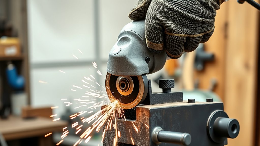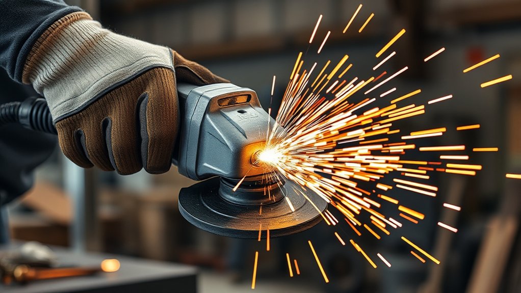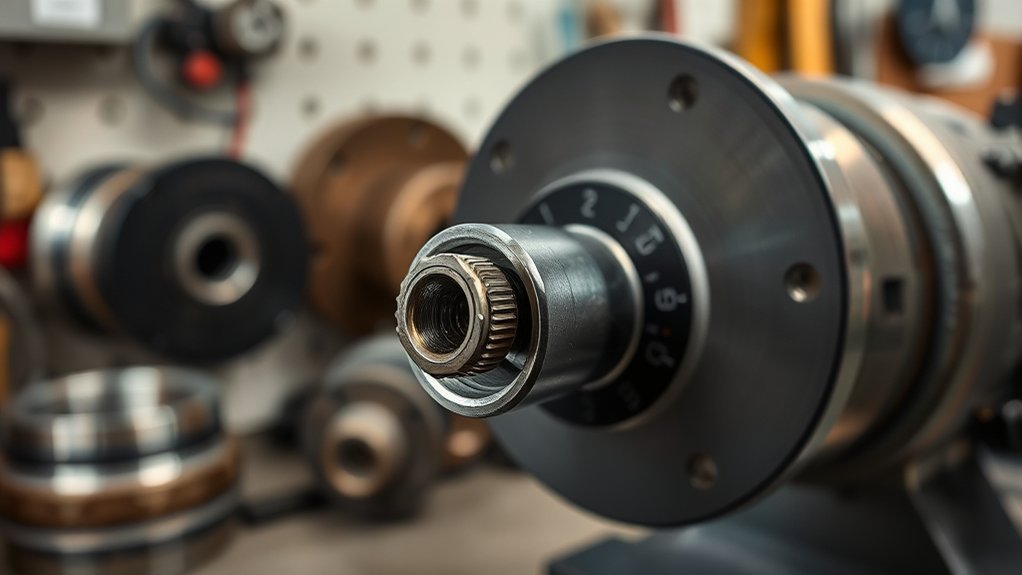
A 5/8-11 spindle thread identifies the threaded output shaft on many conventional angle grinders. The number tells you the nominal thread diameter and pitch, but it does not mean every wheel needs a 5/8-inch center hole. Safe fit depends on the accessory’s mounting style, wheel size and speed rating, the correct guard, and the grinder-specific flange set.
Quick Answer
A 5/8-11 spindle has a nominal 5/8-inch diameter and 11 threads per inch. Threaded accessories must have a matching 5/8-11 hub. Unthreaded wheels may use a 7/8-inch center hole, but they must center on the grinder’s approved backing flange and be secured with the correct lock nut.
Key Takeaways
- 5/8-11 describes the spindle thread, not every wheel’s center-hole diameter.
- A threaded 5/8-11 wheel screws onto the spindle; a plain-bore wheel is clamped and centered by the approved flanges.
- Match the wheel’s diameter, thickness, type, maximum RPM, mounting system, and required guard to the grinder manual.
- Do not force a wheel onto the spindle or use a generic thread adapter unless the tool and accessory manufacturers approve the exact combination.
- Disconnect power before changing accessories, inspect every part, and stop immediately if the grinder vibrates or the wheel runs out of true.
At a Glance
| Time Required | About 2–5 minutes to verify an accessory before mounting |
| Difficulty | Easy, provided you have the model manual and can read the wheel markings |
| Tools Needed | Grinder manual, supplied flange wrench, clean cloth, and good lighting |
| Cost | No added cost when the correct wheel and original mounting hardware are already available |
What Does a 5/8-11 Spindle Thread Mean?
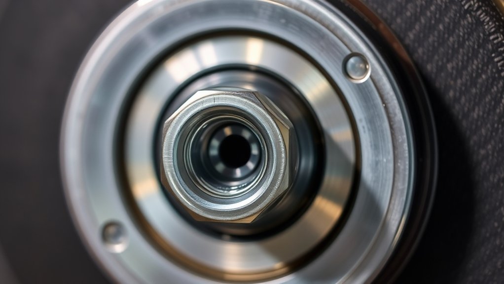
In the 5/8-11 UNC designation, 5/8 inch is the nominal major diameter of the thread, 11 is the number of threads per inch, and UNC identifies the Unified National Coarse thread series. ASME B1.1 covers the designation system for unified inch screw threads.
The spindle thread is only one part of the mounting system. It may accept a wheel with a threaded 5/8-11 hub, or it may hold an unthreaded wheel between a backing flange and lock nut. For example, Makita’s official 9554NB specifications list a 5/8-11 UNC spindle, a 4-1/2-inch grinding wheel, and a 10,000 RPM no-load speed.
The spindle thread and the wheel’s center hole are separate specifications. A wheel fits safely only when its complete mounting system matches the grinder.
Why Can a 7/8-Inch Arbor Wheel Fit a 5/8-11 Grinder?
A plain wheel with a 7/8-inch center hole does not screw onto the 5/8-11 threads. Instead, the wheel fits over the spindle and centers on the raised locating shoulder of the grinder’s backing flange. The matching lock nut clamps the wheel against that flange.
This arrangement is safe only when the grinder manual permits that wheel type and center-hole size, and when the correct backing flange, lock nut, guard, diameter, thickness, and speed rating are used. The 7/8-inch hole by itself does not prove compatibility.
Three Common Angle Grinder Accessory Mounting Styles
| Mounting style | What to look for | How it mounts |
|---|---|---|
| Threaded hub | A marking such as 5/8-11 on the accessory hub | The accessory threads directly onto a matching spindle. The thread size and direction must match exactly. |
| Plain center hole | A center-hole size such as 7/8 inch or another model-specific diameter | The wheel centers on the approved backing flange and is clamped by the correct lock nut. |
| Tool-free proprietary mount | A dedicated interface such as Bosch X-LOCK | The accessory snaps into the matching mount and does not use a traditional threaded spindle, flange nut, or spanner wrench. |
Note: Grinder size and brand do not guarantee a particular mount. Check the exact model number because conventional 5/8-11, metric-thread, and tool-free models can exist in the same general wheel-size class.
Common Grinder Threads: 5/8-11, M10, and M14
Angle grinder spindle standards vary by model and sales market. Never choose an accessory from wheel diameter alone.
| Marking | Meaning | Compatibility point |
|---|---|---|
| 5/8-11 UNC | Nominal 5/8-inch diameter with 11 threads per inch | Common on many conventional grinders sold in North America. A threaded accessory must be marked 5/8-11. |
| M10 x 1.25 or M10 x 1.5 | 10 mm nominal diameter; the second number is the pitch in millimeters | The pitch must match. An M10 accessory with the wrong pitch can start crooked or damage the spindle. |
| M14 x 2 | 14 mm nominal diameter with a 2 mm pitch | Used on many metric-market grinders, but the model manual remains the final authority. |
Do not assume every M10 grinder uses the same pitch. Makita’s official series sheet, for example, lists the 4-inch 9553NB with an M10 x 1.25 spindle and the 4-1/2-inch 9554NB with a 5/8-11 UNC spindle.
Products Worth Considering

[7PCS 5/8"-11 Angle Grinder Nut Wrench Replacement Kit] 1 piece angle grinder wrench and 6 angle grinder nuts (3 inner flange nuts, 3 outer flange nuts) for lock nut removal, wheel/disc replacement.Compatible with most arbor grinders and lock nuts, Perfect for home DIY, workshop projects, and professional grinder parts replacement
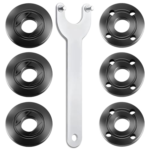
WHAT YOU GET: Includes 1 extended angle grinder wrench and 6 thickened-design flange nuts (3 inner nuts + 3 outer nuts), always have spare nuts to avoid downtime.
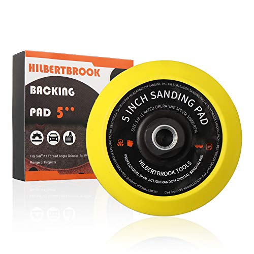
👍 TURN YOUR GRINDER INTO SANDER – 5'' polishing pad fits standard grinders with 5/8-11 threads. Easy to install, holds hook and loop paper perfectly.Better than a random orbit sander, design for your grinder.
How to Choose a Wheel for a 5/8-11 Spindle
- Identify the exact grinder model. Read the nameplate and manual for the spindle or mount type, maximum wheel diameter, rated or no-load speed, approved accessories, flange arrangement, and guard requirements.
- Choose the wheel for the task. Use a grinding wheel for stock removal, a flap disc for blending or finishing, and a cut-off wheel only for cutting. Do not side-load a thin cut-off wheel.
- Match the wheel type to the guard. A grinding guard is not automatically approved for every cut-off wheel. Use the guard type required by the grinder and wheel manufacturers.
- Check diameter and thickness. Both must stay within the grinder’s capacity so the wheel can be guarded and controlled.
- Check the maximum RPM. The accessory’s marked maximum operating speed must equal or exceed the grinder’s rated speed.
- Match the mounting style. A 5/8-11 threaded hub must screw on smoothly by hand. A plain-bore wheel must fit the locating diameter of the approved flange.
- Inspect the wheel and hardware. Do not use a cracked, chipped, warped, wet, expired, dropped, or otherwise damaged wheel. Replace damaged flanges, nuts, guards, or spindle parts with approved parts.
- Mount it with power disconnected. Unplug a corded grinder or remove its battery, follow the manual’s flange orientation, tighten with the supplied wrench as directed, and never over-tighten.
Warning: Never force an accessory onto the spindle, enlarge a wheel’s center hole, stack improvised washers or bushings, remove the guard to clear an oversized wheel, or use a generic thread adapter merely because the parts appear to fit. A mismatched accessory can run out of balance, vibrate, break, or cause loss of control.
Products Worth Considering

【Value Sets】The grinder nut set includes 1 angle grinder wrench and 6 angle grinder nuts (3 inner flange nuts, 3 outer flange nuts). Please check size and compatibility before ordering. Please contact us with any questions or concerns. We prioritize your satisfaction .

1- 5" diameter Knot Cup Brush with a 5/8"-11 arbor.

1- 4" diameter x 1/2" wide Knot Wire wheel with a 5/8"-11 arbor
How to Check Flange and Wheel Compatibility
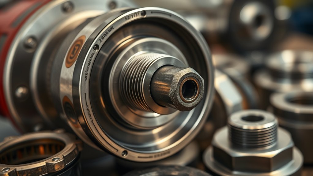
The flange set is part of the grinder’s safety system. The backing flange centers and supports a plain-bore wheel, while the lock nut clamps it in the orientation specified by the manual. These parts are often shaped for particular wheel types and thicknesses, so a nut or flange from another grinder may not be interchangeable even when the spindle thread is the same.
- Use the original or manufacturer-approved flange set. Match the exact grinder model and accessory type.
- Clean the contact surfaces. Remove grit, rust flakes, and metal chips before mounting the wheel.
- Confirm the wheel sits flat. It should contact the intended flange surfaces without rocking, binding, or being forced.
- Follow the lock-nut orientation shown in the manual. The raised or recessed side may face differently for thin and thick accessories.
- Tighten only as directed. OSHA guidance says the spindle nut should hold the wheel without distorting the flange; excessive force can damage the wheel or hardware.
- Spin the wheel by hand before restoring power. It should clear the guard and rotate without rubbing or visible runout.
The Bosch GWS18V-8 manual clearly separates threaded spin-on wheels from flange-mounted wheels: threaded accessories must match the spindle, while a flange-mounted wheel’s arbor hole must fit the flange’s locating diameter.
Pro Tip: Before removing the original wheel, take a clear photo of the flange and lock-nut orientation. Use the photo only as a memory aid; the grinder manual remains the final reference.
What to Do If an Angle Grinder Attachment Does Not Fit
Stop and diagnose the mismatch instead of applying more force. The symptom often points to the cause:
- The accessory will not thread on smoothly: The diameter, pitch, thread direction, or thread condition may be wrong. Remove it immediately and compare the markings with the manual.
- A plain 7/8-inch wheel feels loose on the bare spindle: That can be normal before clamping because the wheel is supposed to center on the backing flange, not on the 5/8-inch threaded shaft. Verify the flange shoulder and manual.
- The wheel rocks or will not sit flat: Check for reversed flanges, the wrong lock nut, debris, a damaged wheel, or a wheel profile the grinder does not support.
- The lock nut bottoms out before clamping: The wheel may be too thin for that nut orientation, or the flange set may be wrong or incomplete. Do not add improvised spacers.
- The wheel clears only when the guard is removed: The wheel is too large, too thick, or the wrong type. Do not use it.
- An adapter seems necessary: Use one only when the grinder manufacturer and adapter or accessory manufacturer explicitly approve the exact models, wheel type, size, speed, and guard arrangement. Otherwise, buy the correctly mounted accessory.
- The grinder vibrates after installation: Switch it off, wait for a complete stop, disconnect power, and inspect the wheel, flanges, spindle, and mounting surfaces. Do not continue testing a visibly unstable setup.
Safe Mounting and Start-Up Checklist
OSHA’s guidance for portable abrasive-wheel tools stresses manufacturer-approved accessories, guards, inspection, correct wheel speed, eye or face protection, and disconnecting power before accessory changes.
- Unplug the grinder or remove the battery before touching the wheel or flange hardware.
- Use the side handle and the correct guard; position the guard between you and the wheel where the manual directs.
- Confirm the wheel’s maximum RPM is at least the grinder’s rated speed.
- Inspect the wheel, backing flange, lock nut, spindle threads, guard, and power tool for damage.
- Secure the workpiece and direct sparks away from people, combustible material, cords, hoses, and finished surfaces.
- Wear task-appropriate eye and face protection, hearing protection, clothing, and respiratory protection required by the material and workplace assessment.
- After mounting, rotate the wheel by hand to check clearance.
- Start the grinder with yourself and bystanders out of the wheel’s plane, let it reach full speed before contacting the work, and stop immediately if you notice unusual noise or vibration.
- Press the spindle-lock button only when the spindle has stopped completely.
Frequently Asked Questions
What is a spindle on an angle grinder?
The spindle is the rotating output shaft that drives the accessory. On a conventional grinder, it may have external threads for a lock nut or a threaded wheel. Other grinders use proprietary tool-free mounts instead.
What thread is used on an angle grinder?
It depends on the exact model. Common conventional threads include 5/8-11 UNC, M10 in more than one pitch, and M14 x 2. Some grinders use a tool-free interface with no traditional spindle thread for the wheel.
Is a 5/8-11 spindle the same as a 5/8-inch arbor hole?
No. A 5/8-11 marking describes a threaded spindle or threaded accessory hub. A plain center hole is a separate diameter specification and usually centers on a flange rather than on the spindle threads.
Can a 7/8-inch arbor wheel fit a 5/8-11 grinder?
Yes, on grinders designed for that arrangement. The wheel must center on the approved backing flange and be secured with the correct lock nut. You must also match the wheel type, diameter, thickness, speed rating, and guard.
Can I use a spindle thread adapter on an angle grinder?
Only when the grinder manufacturer and the adapter or accessory manufacturer approve the exact combination. A generic adapter can alter thread engagement, accessory position, guard coverage, and balance. The safer default is an accessory made for the grinder’s original mount.
What is a spindle lock on an angle grinder?
The spindle lock holds the spindle still while you loosen or tighten mounting hardware. Use it only after the wheel has stopped completely and the grinder has been disconnected from power.
Why does the correct flange size matter?
The flange centers and supports a plain-bore wheel and distributes the clamping force. The wrong flange can leave the wheel off-center, unsupported, distorted, or unable to sit flat.
How can I identify my grinder’s spindle thread?
Check the model nameplate, instruction manual, or official manufacturer specifications. Do not rely only on measuring the outside diameter because metric and inch threads can appear similar and M10 spindles may use different pitches.
Can I use a larger wheel because the spindle thread matches?
No. Matching threads do not make an oversized wheel safe. The wheel must stay within the grinder’s rated diameter and thickness, fit under the correct guard, and have a maximum RPM rating at least as high as the grinder’s speed.
Sources
- ASME B1.1 — Unified Inch Screw Threads — unified inch thread forms and designation.
- Makita 9553NB/9554NB/9557NB/9558NB Series Specifications — model-specific spindle threads, wheel sizes, and no-load speeds.
- Bosch GWS18V-8 Instruction Manual — threaded versus flange-mounted accessories, speed ratings, guards, flange installation, and inspection.
- OSHA: Safe Use of Portable and Hand-Held Power Tools — abrasive-wheel inspection, guards, PPE, wheel speed, mounting, and start-up safety.
- OSHA 29 CFR 1910.243 — guarding and wheel-speed requirements for portable powered tools.
- Bosch GWX13-50VSP X-LOCK Grinder — current example of a tool-free mounting system without a traditional threaded wheel interface.
Conclusion
A 5/8-11 spindle thread means a nominal 5/8-inch thread with 11 threads per inch, but that number alone does not determine whether a wheel is safe to use. Confirm whether the accessory is threaded or flange-mounted, then match its type, center hole or hub, diameter, thickness, maximum RPM, flange set, and guard to the exact grinder model. When anything binds, rocks, rubs, or requires an improvised adapter, stop and use the correct manufacturer-approved parts instead.