A plasma cutter torch lead is not a generic cable you can size by outer diameter or replace with any lead that reaches. It is a matched assembly that may carry cutting current, pilot-arc current, start and safety signals, compressed gas, and—in some industrial systems—coolant. The correct choice depends on the exact power source, torch family, connector, process, and manufacturer-approved length.
Quick Answer
There is no universal best torch lead length or safe minimum outer diameter. Use the OEM-approved lead assembly listed for your exact plasma cutter and torch. Choose the shortest approved length that reaches without tension, kinks, tight bends, or unsafe routing, and never size or splice a lead by appearance alone.
Key Takeaways
- Match the lead by power-source model, serial range, torch family, connector, process, and OEM part number—not by outside diameter.
- Approved torch leads vary widely in length. Current and recent systems use leads from about 10 feet to 75 feet, depending on the machine and torch.
- A longer lead is safe only when the manufacturer designed and approved that assembly for the system.
- Replace leads with cuts, cracks, hot spots, crushed sections, loose fittings, damaged strain relief, or intermittent connections.
- Do not use generic wire-gauge, solder, or air-hose splice advice on a plasma torch lead unless the manufacturer publishes a model-specific repair procedure.
At a Glance
| Time Required | 10–20 minutes to identify and inspect a lead; replacement time varies by model |
| Difficulty | Easy for inspection and detachable replacement; advanced for internal or hard-wired service |
| Tools Needed | Operator manual, model and serial information, tape measure, flashlight, and only the model-specific tools named in the service procedure |
| Cost | Inspection is free; replacement cost depends on torch family, lead length, connector, and whether the torch is included |
Why Torch Lead Size Matters for Plasma Cutting
The torch lead connects the torch to the plasma power source, but it is more complex than an ordinary electrical cord. Depending on the system, the assembly can contain a main power conductor, pilot-arc conductor, trigger and parts-in-place wiring, gas hose, shielding, and protective jacket. High-amperage industrial systems may also use coolant and separate process-gas lines.
Lead length affects reach, routing, drag, bend radius, and the electrical and gas characteristics the manufacturer must account for. Lead construction affects current capacity, gas delivery, shielding, durability, and flexibility. Those details are designed as a complete system.
Note: The outside diameter of the finished lead bundle does not reveal conductor gauge, hose inside diameter, shielding, insulation temperature rating, or connector pinout. Two leads that look alike can be electrically and mechanically incompatible.
The correct torch lead is identified by an approved part number and system compatibility—not by a universal length, outer diameter, or visual match.
Using the wrong assembly can cause failure to start, gas-flow faults, intermittent control signals, connector damage, poor machine motion, or a serious shock and fire hazard. It may also defeat torch safety circuits or void equipment certification and warranty coverage.
Recommended Torch Lead Lengths by Application
There is no universal 10–12-foot handheld rule, 16–19-foot shop rule, or 19–25-foot CNC rule. Manufacturer offerings show a much wider range. For example, the Lincoln Electric Tomahawk 30 AIR is sold with a 10-foot hand torch, while the Miller Spectrum 625 X-TREME uses a 12-foot XT40 torch assembly.
At the other end of the range, Hypertherm lists approved cable options from 15 to 75 feet for different Duramax Lock torch configurations on the Powermax45 XP. Lincoln also sells the Tomahawk 1000 with a 25-foot hand torch. These examples show why application alone cannot determine the correct length.
| Application | Selection Rule | Routing Check |
|---|---|---|
| Portable handheld cutting | Use an approved lead long enough to reach the work without pulling the power source | Avoid trip hazards, hot slag, vehicle traffic, and sharp edges |
| Fixed shop or fabrication bench | Choose among the OEM lengths listed for the exact torch and power source | Allow a relaxed service loop without tight coils or tension |
| CNC table or track system | Use an approved machine-torch lead that covers full travel plus the required service loop | Meet the specified bend radius and cable-carrier requirements at every axis position |
Pro Tip: Measure the actual route, not the straight-line distance. Include vertical movement, gantry travel, a relaxed service loop, connector access, and the lead’s minimum bend radius. Then choose the shortest OEM-approved option that covers that route.
How Lead Construction Affects Amperage, Gas Flow, and Flexibility
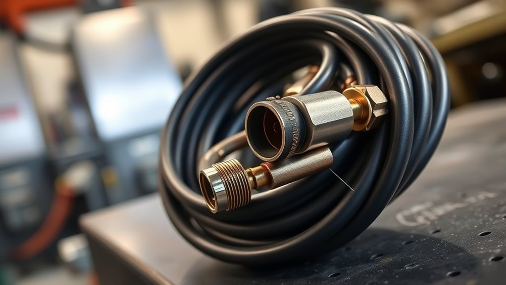
A plasma torch lead must carry the system’s rated current without excessive heating while also delivering the required gas flow and maintaining control and safety circuits. Manufacturers meet those needs by selecting conductor size, hose dimensions, insulation, shielding, fittings, and jacket construction as a matched assembly.
A larger outside diameter does not automatically mean higher current capacity or better gas flow. The jacket may be thicker for abrasion resistance, the hose may be reinforced, or the assembly may contain extra signal or coolant lines. Likewise, a thinner-looking lead may use different conductor materials or insulation and still be correct for its specific system.
Flexibility also depends on strand count, conductor construction, jacket material, reinforcement, temperature, and bend radius. A physically larger lead is often heavier and may be less flexible, not more flexible. Never substitute visual thickness for an OEM current rating or part number.
- Amperage: Match the lead to the torch and power source output range stated by the manufacturer.
- Gas delivery: Use the approved assembly and keep it free of crushing, kinks, leaks, and tight bends.
- Cooling: Air-cooled and liquid-cooled systems use different lead designs and cannot be interchanged.
- Signals and safety circuits: Trigger, cap-sensor, ohmic, communication, and pilot-arc connections must match exactly.
- Duty cycle: Follow the system’s rated duty cycle; do not assume a thicker-looking lead increases it.
Extending or Replacing a Hard-Wired Torch Lead
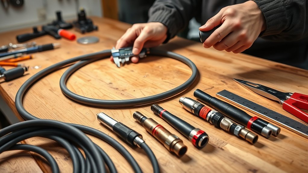
Warning: Plasma cutting systems use hazardous voltage and high-current DC power. Disconnect input power and the gas supply before inspection or service. Internal repairs and hard-wired lead replacement should be performed only by people qualified for the exact procedure in the manufacturer’s service documentation.
Detachable torch leads are usually replaced as complete assemblies. Hard-wired systems may require opening the power source or torch, disconnecting gas and electrical fittings, transferring strain relief, and testing safety circuits. The correct procedure varies by model.
Products Worth Considering

APPLICATION: Apply to YESWELDER CUT-60DS PRO, CUT-65DS PLUS,CUT-65DS PRO plasma cutter with central interface.
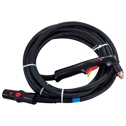
Hypertherm Powermax 45 Plasma Cutter 20' Hand Torch 088008

13 Feet SG55/AG-60 plasma torch assembly, max. 239 psi air pressure, 60% duty cycle at 60 amp
Assessing Torch Compatibility
Before ordering a replacement, record the power-source model, serial number, torch model, hand or machine configuration, existing lead part number, connector type, and lead length. Then verify the replacement in the current parts list or operator manual.
- Confirm the lead is approved for the exact power source and serial range.
- Match the torch family, amperage range, gas or coolant configuration, and hand or machine use.
- Match the power, pilot-arc, trigger, cap-sensor, ohmic, and communication interfaces.
- Use the manufacturer’s listed lead length and part number.
- Check whether replacing the lead alone is supported or whether the torch-and-lead assembly must be replaced together.
Why Generic Splicing Advice Is Unsafe
There is no safe universal instruction such as “use at least 14 AWG,” “use a 20–40 amp connector,” or “solder and heat-shrink the conductors.” Those figures can confuse pilot-arc current with main cutting current and ignore gas fittings, shielding, insulation ratings, safety interlocks, strain relief, and high-frequency starting circuits.
Some manufacturers publish field-service bulletins for replacing a specific lead with a preassembled service kit. That is different from inventing an extension or patch. Follow such a bulletin only when it names your exact torch and system, and use every specified part, torque value, test, and safety step.
Do not install an ordinary compressed-air hose, welding cable, extension cord, generic multi-pin plug, or hand-built adapter in place of an approved torch lead. A splice that passes a simple continuity test can still fail under load, leak gas, interfere with starting, overheat, or bypass a safety circuit.
When to Use Professional Service
Use an authorized service provider or a technician qualified on the system when the lead is hard-wired, the power source must be opened, the correct part number is uncertain, the connector is damaged, or the repair requires pressure, insulation, high-voltage, or functional safety testing.
A professional should verify more than continuity. Proper service may include gas-leak testing, insulation and connection checks, cap-sensor and trigger testing, pilot-arc operation, strain relief, fault-code review, and a controlled cut test.
Installation Best Practices and Routing Considerations
Correct routing prevents mechanical damage and helps the lead perform as designed. Follow the lead’s model-specific bend-radius limit rather than a generic number. For example, Hypertherm’s Powermax SYNC mechanized integration guidance gives a 3-inch minimum bend radius for that torch lead, while other industrial systems specify different limits.
- Seat detachable connectors fully and engage their locking mechanism.
- Keep the lead away from hot plate, molten slag, sharp sheet edges, grinding sparks, standing water, and traffic paths.
- Do not pull the power source by the torch lead or let the lead support the torch’s weight.
- Use strain relief at the torch, power source, and cable carrier without clamping hard enough to crush the assembly.
- Keep bends broad and prevent twisting, pinching, or flattening throughout the full machine travel.
- Do not wrap or drape the torch lead around your body.
- On CNC systems, separate communication and control cables from the torch lead as the equipment manufacturer directs to reduce electrical noise.
- Keep the work connection clean, secure, and placed according to the machine manufacturer’s grounding instructions.
Inspect the route with the torch at every travel limit. A lead that looks relaxed at the home position may be stretched, crushed, or bent too tightly at the far corner of a CNC table.
For broader hot-work controls, ventilation, fire prevention, and personal protective equipment, follow OSHA’s welding, cutting, and brazing guidance and the safety section of your plasma cutter manual.
Troubleshooting Voltage, Signal, and Air-Flow Problems
Do not begin by probing live torch voltage or guessing that lead length is the cause. Plasma systems can contain lethal voltage, and poor cut quality is more often tied to consumables, air supply, work connection, torch height, travel speed, or setup. Start with safe visual checks and the machine’s fault information.
| Symptom | Safe Checks | Next Action |
|---|---|---|
| Torch will not start or starts intermittently | Check the displayed fault, consumable installation, connector seating, trigger, visible damage, and loose external fittings | Replace a damaged approved assembly or use qualified service for internal testing |
| Low-flow or gas-pressure fault | Check compressor capacity, regulator setting, filters, supply hose, lead kinks, crushed sections, and leaks | Correct the restriction; never raise pressure above the manufacturer’s setting to mask a fault |
| Rough edge, heavy dross, or unstable arc | Inspect consumables, air quality, work connection, amperage, travel speed, torch height, and lead condition | Use the cut chart and isolate one variable at a time |
| Hot spot, burned jacket, odor, arcing, or exposed conductor | Stop immediately and disconnect input power | Remove the lead from service and replace it with the correct approved assembly |
| CNC resets, noisy signals, or erratic height control | Check grounding, shielding, cable separation, connector condition, and routing | Follow the plasma and table manufacturers’ EMI and integration instructions |
Hypertherm’s maintenance guidance says to examine torch leads for kinks, cracks, cuts, damage, loose connections, and bend-radius violations, then replace the lead when damage is found. That is safer than attempting to prove a generic “5% voltage-drop” threshold at the torch.
Selecting Compatible Leads for Popular Plasma Cutter Models
Compatibility must be verified from the manufacturer’s current parts information. Brand name alone is not enough because one brand may use several torch families, connector styles, amperage ranges, and hand or machine configurations.
Products Worth Considering

APPLICATION: Apply to YESWELDER CUT-65DS/CUT-55DS PRO/CUT-55NHF/CUT-55NHF PLUS plasma cutters. Replacement for the S45 Plasma Cutting Torch.

20pcs Plasma Tips Nozzle Extended Ref No: 18866L

【INDUSTRIAL-GRADE SPLIT LEATHER PROTECTION】: Constructed from premium heavy-duty split leather, this welding lead sleeve offers unmatched abrasion resistance. It acts as a rugged protective wrap for your expensive equipment, ensuring long-lasting performance in the harshest metalworking environments without adding unnecessary weight.
Model, Serial Number, and Length Requirements
Start with the data plate and the existing torch label. A model may change connectors or compatible assemblies across production revisions, so record the serial number as well as the model. Then use the operator manual, parts list, or manufacturer support page to find the approved torch and lead part number.
- Identify the exact power-source model and serial number.
- Identify the torch family and whether it is handheld, machine, robotic, or specialty.
- Confirm the rated cutting-current range and process, including cutting, gouging, marking, or FineCut-type work.
- Choose from the approved lead lengths listed for that combination.
- Confirm the route can meet bend-radius, strain-relief, and full-travel requirements.
Connector and Pinout Safety
Do not assume two connectors with the same number of pins share the same pinout. Plasma torch connectors may combine main power, pilot arc, start switch, parts-in-place sensing, torch identification, communication, and gas connections. A wrong connection can damage the torch or power source and can disable a safety function.
| Compatibility Item | What Must Match |
|---|---|
| Power source | Model, serial range, output current, and supported torch family |
| Torch | Hand or machine type, head design, consumable platform, and process |
| Lead assembly | OEM part number, approved length, gas or coolant design, and strain relief |
| Connector | Mechanical keying, power contacts, control pinout, locking method, and gas seal |
| CNC integration | Machine-torch support, start/transfer signals, divided voltage or serial interface, grounding, and cable routing |
Get a manufacturer wiring diagram only when building or repairing an interface the manufacturer permits. Never reverse-engineer a torch pinout by trial and error.
Handheld and CNC Torch Compatibility
A handheld torch and a machine torch for the same power source may use different bodies, safety controls, mounting features, consumables, and lead lengths. CNC systems also need enough lead for full motion, a compatible cable carrier, correct grounding, and separation between high-current torch wiring and sensitive control or communication cables.
Do not use nozzle diameter to infer torch-lead gas capacity. Nozzle orifice size is a consumable-process specification. The approved lead assembly is selected from the torch and power-source documentation.
- Confirm the manufacturer permits the chosen torch type on the power source.
- Use the listed machine-torch lead for automated tables rather than adapting a hand torch unless the manufacturer supports that setup.
- Verify any CPC, divided-voltage, serial, ohmic, or remote-start interface separately from the torch lead.
- After installation, test motion without firing, then perform the manufacturer’s startup and cut-quality checks.
Torch Lead Inspection and Maintenance Checklist
Inspect the lead before use and whenever cut behavior changes. High-use CNC systems may need a formal daily or shift-based inspection, while occasional handheld systems should still be checked before every job.
- Disconnect input power before touching damaged connectors or opening any cover.
- Look for cuts, cracks, burns, exposed material, flattened sections, blistering, and abrasion.
- Check both strain-relief points for separation, looseness, or sharp bending.
- Check detachable connectors for dirt, damaged seals, bent contacts, looseness, or incomplete locking.
- Run the lead through its full CNC travel and watch for pulling, twisting, crushing, or bend-radius violations.
- Check for air or gas leaks using only the method approved in the manual.
- Keep the jacket clean and dry; do not use solvents that the manufacturer has not approved.
- Replace the assembly when damage is found rather than covering a defect with tape or an unapproved sleeve.
Frequently Asked Questions
Can torch leads be used in cold weather without insulation modifications?
Use the torch only within the operating and storage temperature limits in its manual. Cold jackets can become stiff, so let the lead warm naturally and bend it gently. Do not add insulation, heat tape, or a replacement jacket unless the manufacturer approves it, because modifications can hide damage, trap heat, or violate bend-radius limits.
Are there flame-resistant lead options for hot-work environments?
Some OEM assemblies use jackets designed for harsh cutting environments, but compatibility still controls the choice. Do not substitute a generic silicone, PTFE, or fiberglass-sleeved cable. Route the approved lead away from hot plate and slag, and use only a protective sleeve specifically allowed by the equipment manufacturer.
How do torch leads affect electromagnetic interference near electronics?
EMI depends on the plasma system, starting method, shielding, grounding, bonding, cable routing, and separation from control wiring. Follow the plasma and CNC manufacturers’ integration instructions. Do not assume ordinary insulation increases or decreases EMI; the complete shielding and grounding design matters.
Can lead length affect consumable wear?
An OEM-approved length should operate as designed. A damaged, leaking, crushed, kinked, coiled, or incompatible lead can contribute to poor gas flow or unstable starting, which may shorten consumable life. Check air quality, pressure, consumable installation, torch height, and cutting technique before blaming length alone.
Are plasma torch quick-disconnects standardized across manufacturers?
No universal cross-brand quick-disconnect standard guarantees compatibility. Similar-looking plugs can use different contacts, pinouts, gas seals, communication methods, and locking systems. Match the exact OEM part number or a replacement explicitly approved for the model and serial range.
Can I add an extension to a plasma cutter torch lead?
Only when the manufacturer lists an approved longer assembly, extension, or model-specific conversion procedure. Do not add ordinary cable and air hose. When more reach is needed, the safest solution is usually an approved longer torch-and-lead assembly or moving the power source closer while maintaining required ventilation and electrical access.
Is the torch lead the same as the work cable?
No. The torch lead connects the power source to the torch and may carry power, gas, and control functions. The work cable connects the power source to the workpiece or cutting table to complete the cutting circuit. Both must be compatible, undamaged, and connected as the manufacturer directs.
Conclusion
The right plasma cutter torch lead is the approved assembly for your exact power source, serial range, torch, process, connector, and working distance. Do not rely on universal length ranges, outer diameter, generic wire gauge, or improvised splices. Select the shortest approved length that reaches safely, route it within its bend-radius limit, inspect it often, and replace damage with the correct part.
That model-specific approach protects arc performance, gas delivery, safety circuits, equipment life, and operator safety without guessing at hidden lead construction.
Sources
- OSHA: Welding, Cutting, and Brazing — hot-work hazards, standards, and safety resources
- Hypertherm Safety and Compliance Manual, Revision 9 — equipment inspection, qualified repair, electrical, fire, fume, and cutting safety
- Hypertherm Powermax45 XP torch and cable options — approved torch configurations and cable lengths
- Hypertherm Powermax SYNC mechanized integration — bend radius, cable routing, grounding, and communication-cable separation
- Hypertherm XPR170: Examine the torch lead — inspection, damage criteria, connections, and replacement guidance
- Miller Spectrum 625 X-TREME product information — manufacturer example of a model-specific torch assembly