I tried to run a bead on a thick steel plate using an old stick welder in the shop—the arc sputtered, the electrode kept sticking, and the bead looked nothing like the smooth joint I wanted. The problem was not only technique or electrode choice. The welding power source and its transformer also affected how the arc started and behaved.
A welding transformer is used in conventional arc-welding machines to reduce mains voltage and supply the low-voltage, high-current output needed to maintain an arc. A basic AC transformer can power certain stick-welding electrodes, while a transformer-rectifier adds components that produce DC. Modern inverter welders also use transformers, but at much higher switching frequencies, which allows a smaller and lighter design.
Understanding the transformer helps you choose the right machine, diagnose poor arc performance, respect duty-cycle limits, and avoid dangerous electrical shortcuts. It does not replace the welder’s manual, the electrode manufacturer’s data, or a qualified welding procedure for structural, pressure, automotive, or other safety-critical work.
Quick Answer
A welding transformer uses electromagnetic induction to step mains AC down to a lower voltage while making high welding current available. Conventional transformer welders are durable but heavy. AC models feed the arc directly, while transformer-rectifier machines convert the output to DC for electrodes and processes that require it.
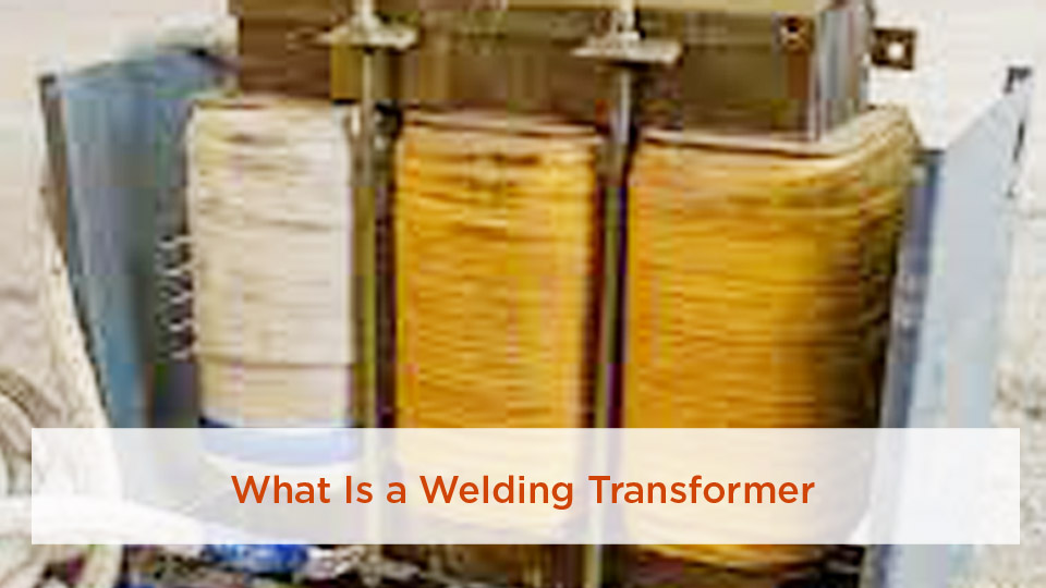
Image by fbsp.ftu.edu
Key Takeaways
- A welding transformer lowers voltage and makes high current available; it does not make the welding circuit harmless.
- Stick welding normally needs a constant-current power source, while most MIG welding needs constant-voltage DC output and a wire feeder.
- Input power, polarity, amperage range, open-circuit voltage, and duty cycle are model-specific—use the nameplate and manual.
- The work lead completes the welding circuit; it is not the same as the equipment-grounding conductor for the machine frame.
- Never add a homemade rectifier, change internal taps, or open the cabinet unless the manufacturer authorizes the work and a qualified technician performs it.
At a Glance
| Time Required | About 15–30 minutes for a pre-use inspection and setup; longer if a suitable branch circuit must be installed |
| Difficulty | Beginner to intermediate for normal operation; electrical installation and internal service require qualified personnel |
| Tools Needed | Welder manual, correct electrodes, welding helmet, dry gloves and clothing, work clamp, wire brush or grinder, ventilation, and a suitable fire extinguisher |
| Cost | No extra setup cost when the correct circuit and PPE already exist; circuit installation, cable replacement, and repairs vary by site and machine |
How Does a Welding Transformer Work?
A conventional welding transformer works by electromagnetic induction. Alternating current in the primary winding creates a changing magnetic flux in a laminated steel core. That changing flux induces voltage in the secondary winding. The ratio between primary and secondary turns largely determines the voltage ratio.
The secondary winding normally has fewer turns made from heavier conductor. The lower turn count reduces voltage, while the larger conductor is built to carry high current. The laminated core limits eddy-current heating. Copper loss, core loss, leakage reactance, and cooling design determine how much heat the machine produces and how long it can operate at a given output.
Welding voltage must be described in two conditions:
- Open-circuit voltage (OCV): the voltage available before the arc is established. It helps the electrode start and restrike.
- Arc or load voltage: the lower voltage measured while welding current is flowing.
For a model-specific example, Lincoln Electric’s conventional AC225 is rated at 225 amps and 25 volts at 20% duty cycle, with a maximum OCV of 79 volts. Its input is 230-volt, single-phase, 60-hertz power, and it draws 50 amps at rated output. Those numbers describe that machine only; another transformer welder may have very different requirements. See the manufacturer’s AC225 specification.
Warning: Lower welding voltage does not eliminate shock risk. The electrode and work circuits are electrically live when output is on. Keep gloves and clothing dry, stay out of wet conditions, and never treat your body as part of a grounding path.
Why Stick Welders Use a Drooping Output
Most stick-welding power sources are designed as constant-current machines. Their output voltage drops as current rises, which helps limit large current changes when the welder’s hand slightly changes arc length. This “drooping” volt-amp characteristic is one reason an older transformer stick welder can maintain a usable arc without digital controls.
Most MIG systems use constant-voltage DC instead. A plain AC stick transformer is therefore not automatically suitable for MIG welding. A complete MIG power source also needs the correct output characteristic, rectification when DC is required, inductance and control components, a wire feeder, a gun, and the proper shielding system.
How AC Becomes DC
A transformer produces AC at its secondary winding. A purpose-built transformer-rectifier machine routes that output through high-current rectifiers and may use inductors or other filtering components to shape the arc. The result is DC output with selectable electrode polarity on machines designed for that feature.
Do not assume that adding a few diodes converts an AC welder safely. Rectifiers must withstand welding current, reverse voltage, heat, and fault conditions. The enclosure, cooling, insulation, conductor size, protective devices, and output controls must also be engineered for the change.
Key Components of a Welding Transformer
- Laminated magnetic core: carries the alternating magnetic flux while limiting eddy-current loss.
- Primary winding: connects to the input supply and usually has many turns of smaller conductor.
- Secondary winding: provides low-voltage, high-current output through fewer turns of heavier copper or aluminum conductor.
- Current-control system: may use tapped windings, a movable magnetic shunt, a movable core, a reactor, or another model-specific method.
- Rectifier and inductor: appear in transformer-rectifier DC machines, not in every transformer welder.
- Insulation system: separates windings, the core, and the enclosure at the required electrical and thermal ratings.
- Cooling system: may be natural-air, fan-cooled, or another design specified by the manufacturer.
- Enclosure and controls: protect live parts and provide the approved switch, selector, terminals, thermal protection, and input connection.
A hum by itself can be normal in a line-frequency transformer, but a new harsh buzz, burning smell, smoke, repeated thermal shutdown, or visible insulation damage is not a troubleshooting invitation. Disconnect the machine and have it inspected by qualified service personnel.
Note: Internal capacitors or other components may retain hazardous energy after the machine is unplugged. Removing the cover is not a normal owner-maintenance step unless the manual expressly permits it.
Types of Welding Transformers
Welding machines are better classified by electrical architecture and output than by broad labels such as “hobby” or “industrial.” Cooling method, duty cycle, weight, and process capability vary by model.
| Type | Typical Output | Best Fit | Main Trade-Off |
|---|---|---|---|
| Line-frequency AC transformer | AC, usually constant current for stick welding | Shop, farm, training, repair, and light fabrication with AC-rated electrodes | Heavy and limited to compatible processes and electrodes |
| Transformer-rectifier | DC or AC/DC, depending on design | Stick, TIG, MIG, or submerged-arc service when the complete power source is designed for that process | More components, more heat to manage, and still relatively heavy |
| High-frequency inverter with transformer | Precisely controlled AC or DC | Portable and multi-process work | More complex electronics and model-specific repair requirements |
Air cooling is common, but the word “air-cooled” does not tell you the duty cycle. Likewise, liquid- or oil-cooled industrial equipment is not automatically rated for continuous output. Read the nameplate and duty-cycle chart at the amperage you plan to use.
Advantages of Using a Welding Transformer
- Simple, proven architecture: conventional machines can have fewer electronic controls than an inverter.
- Rugged stationary service: a properly maintained transformer welder can be a dependable shop machine.
- Strong output for compatible electrodes: many classic AC stick welders cover useful farm, repair, and fabrication ranges.
- Direct controls: tapped selectors or mechanical current controls are easy to understand.
- Repair potential: qualified shops may be able to service switches, fans, leads, rectifiers, or windings when parts and technical information are available.
The advantage is not that a transformer “forces” a good weld. Weld quality still depends on joint design, base-metal condition, electrode classification, polarity, current, arc length, travel speed, heat input, operator skill, and any required welding procedure.
Limitations of Welding Transformers and How to Work Around Them
The main limitation is weight. A line-frequency core and windings are physically large, so conventional welders are often best left on a cart or installed in a fixed work area. Use lifting points and handling methods specified by the manufacturer; do not improvise a lift from cables, handles, or sheet-metal covers.
Older machines may also offer coarse current steps, AC-only output, lower efficiency, more idle loss, or fewer arc-control features than a modern inverter. Work around those limits by selecting electrodes made for the available output, using the correct diameter, maintaining short and sound cable connections, and testing settings on representative scrap.
Do not try to solve thin-sheet burn-through simply by changing electrode classification. Use a smaller electrode, a suitable low-current range, tight fit-up, controlled travel, and—when the work is too thin for the machine—a more appropriate process such as short-circuit MIG or controlled TIG.
When to Use a Welding Transformer in Your Projects
A conventional transformer stick welder makes sense when the machine’s output matches the electrode and the job. Typical uses include home, farm, maintenance, build-up, and light fabrication on compatible steels and cast iron, as listed for the AC225 example.
Stick welding is often more tolerant of outdoor air movement than gas-shielded MIG because the electrode flux generates shielding at the arc. Strong wind can still disturb the arc and slag system, and outdoor work still needs fire control and fume awareness.
Do not treat a transformer welder as blanket approval for structural beams, pressure piping, vehicle frames, reinforcing steel, high-strength steel, stainless, or aluminum. Those jobs may require material identification, an approved filler, a qualified welding procedure specification, preheat or interpass controls, welder qualification, inspection, and engineering approval.
Step-by-Step Guide to Setting Up Your Welding Transformer
- Read the nameplate and manual. Confirm input voltage, phase, frequency, rated input current, output range, duty cycle, polarity options, electrode limits, and environmental restrictions.
- Prepare a fire-safe work area. Move combustibles at least 35 feet where practical, protect anything that cannot be moved, check hidden spaces, and keep suitable extinguishing equipment ready. Use a fire watch when the conditions require one.
- Inspect the machine and leads. Look for a damaged plug, loose terminals, cracked insulation, exposed conductor, contaminated work-clamp faces, blocked vents, leaks, or signs that the machine has been wet. Replace damaged welding cable; do not rely on tape over exposed conductor.
- Verify the supply. Use the input voltage, conductor size, overcurrent protection, receptacle, plug, disconnect, and equipment grounding required by the machine and applicable electrical rules. Have a qualified electrician install or correct the branch circuit.
- Place the welder correctly. Keep it dry, stable, ventilated, and away from sparks, grinding dust, spray, and blocked airflow. Secure a wheeled unit against unintended movement.
- Connect the welding circuit. Attach the work lead firmly to clean metal on the workpiece or approved work table, as close to the weld as practical. The work lead completes the welding circuit; it does not replace the machine’s equipment-grounding connection.
- Select the electrode and polarity. Match classification, diameter, polarity, position, base metal, and joint requirements to the machine manual, electrode data, and any WPS. Use an electrode specifically rated for AC when the machine provides AC only.
- Set amperage from approved data. Start within the electrode manufacturer’s range for the chosen diameter and position. Make a test bead on representative scrap, then adjust in small steps.
- Strike and maintain the arc. Use the work angle required by the joint and a modest travel angle. Hold a short, consistent arc unless the electrode instructions say otherwise. “Stick-out” is a wire-welding term; in stick welding, control arc length as the electrode burns down.
- Respect duty cycle. Duty cycle is the percentage of a 10-minute period that the machine can weld at its rated output without overheating. At 20% duty cycle, that means two minutes of welding followed by eight minutes of cooling at the stated output.
- Shut down safely. Remove the electrode from the holder during extended stops, place the holder where it cannot contact people or conductive objects, switch off the machine, and disconnect input power before permitted inspection or service.
Pro Tip: Write the electrode classification, diameter, polarity, amperage, joint type, and result on a scrap test plate. That small log is more useful than copying a single “magic” amperage from another welder.
Common Mistakes with Welding Transformers and Fixes
| Mistake or Symptom | Likely Causes | Safe Fix |
|---|---|---|
| Electrode sticks repeatedly | Current too low, poor work connection, excessive cable loss, wrong electrode for AC, damp electrode, or an arc held too short | Clean and tighten connections, verify cable size and electrode compatibility, then adjust within the electrode’s approved range |
| Arc sputters or wanders | Dirty metal, weak work connection, wrong polarity, damaged lead, unstable supply, or an unsuitable electrode | Clean the joint and clamp area, verify polarity and supply, replace damaged leads, and test a fresh compatible electrode |
| Excessive spatter or undercut | Current too high, arc too long, wrong angle, wrong polarity, contamination, or poor travel speed | Return to the electrode data range, shorten the arc, correct technique, and clean the joint |
| Machine overheats | Duty cycle exceeded, blocked airflow, high ambient temperature, fan fault, loose high-resistance connection, or internal defect | Stop welding, leave power and fan operation as the manual directs, clear external airflow, reduce output or duty cycle, and obtain service if shutdown repeats |
| Breaker or fuse opens | Incorrect branch circuit, excessive input demand, damaged cord, short circuit, or machine fault | Stop resetting the device, compare the installation with the nameplate and manual, and have an electrician or qualified technician diagnose it |
| Smoke, burning odor, arcing inside, or unusual noise | Loose connection, insulation failure, contaminated switchgear, failed rectifier, winding damage, or another serious fault | Switch off and disconnect the machine immediately; do not use it until qualified service confirms it is safe |
Moisture-sensitive electrodes must be stored and reconditioned according to their classification and the manufacturer’s instructions. Lincoln Electric’s electrode storage and redrying guidance shows why one blanket oven temperature is not suitable for every rod. Do not use a food oven for welding consumables.
Maintenance Tips for Your Welding Transformer
Maintenance starts with the manufacturer’s schedule. OSHA requires users to follow the printed operating instructions and to discontinue use until safety is assured when defects are found. Repairs should be made only by qualified personnel.
- Before use: inspect the input cord, plug, holder, work clamp, terminals, cable insulation, vents, switches, and enclosure.
- At scheduled intervals: disconnect input power and clean the machine only by the method and air-pressure limit stated in the manual. Miller notes that some power sources may need internal blowing or vacuuming about every six months, or more often in heavy service.
- After wet exposure: do not simply let the exterior dry. The machine must be thoroughly dried and tested before use.
- For damaged cables: replace cables with damaged insulation or exposed conductor. Use purpose-made, properly insulated connectors when joining approved cable lengths.
- For oil- or liquid-cooled equipment: inspect and service the cooling medium only at the interval and with the material specified for that model.
- For storage: keep the welder dry, covered from contamination without blocking ventilation during operation, and protected from impact.
Miller’s welding-machine maintenance guidance also explains the difference between the work lead and the machine’s grounding connection.
Choosing the Right Welding Transformer for Your Needs
Start with the process, not the maximum amp number printed on the cabinet.
- Output characteristic: constant current for stick and many TIG applications; constant voltage for most MIG applications.
- AC, DC, or AC/DC: match the output to the electrode or process data.
- Input requirements: voltage, phase, frequency, rated input current, plug, conductor, disconnect, and overcurrent protection.
- Useful amperage range: make sure the machine can run the electrode diameters and material thicknesses you actually use.
- Duty cycle at your working output: compare ratings at the same current and ambient conditions.
- OCV and electrode compatibility: some electrodes are easier to start or maintain on specific output types.
- Control resolution: tapped selectors are simple; continuous magnetic or electronic controls allow finer adjustment.
- Portability: compare real machine weight, dimensions, wheels, lifting provisions, and site power.
- Service support: check manual availability, parts, qualified repair options, and recognized safety listings.
Do not “test” a welder in rain or on a wet floor. A stable arc in unsafe conditions is not proof of a safe machine.
Products Worth Considering

All-Scenario No-Power-Cut Current Monitoring:scenarios like live retrofits in substations/workshops, online monitoring for motors/frequency converters, post-construction current metering in buildings, and temporary testing during power maintenance—avoiding downtime losses while realizing flexible current measurement and signal transmission (compatible with ammeters, PLCs).

5A 75W large power, in addition to the function of current limit, voltage stabilizing and step-down, the module can also be used as a high power LED constant current driver module and charging module for the lithium battery of usb connector.

Welding Transformer vs. Inverter Welder: Quick Comparison
| Feature | Conventional Transformer | Inverter |
|---|---|---|
| Weight and size | Usually larger and heavier because it operates at line frequency | Usually smaller and lighter because it uses high-frequency conversion |
| Controls | Often simple, with tapped or mechanical current adjustment | Often offers fine adjustment, hot start, arc force, pulse, and multi-process modes |
| Input efficiency | Generally lower, with more core and idle loss | Generally higher, though power factor and generator compatibility remain model-specific |
| Durability | Proven and mechanically simple, but still vulnerable to moisture, overheating, impact, and insulation failure | Can be rugged when properly sealed and rated, but contains more power electronics |
| Best use | Fixed shop work where simple operation and weight are acceptable | Portable, generator-powered, precise, or multi-process work |
| Purchase decision | Condition, output type, duty cycle, and serviceability matter more than age alone | Features, environmental rating, input range, warranty, and repair support matter more than low weight alone |
I still like a conventional transformer for a fixed shop machine and an inverter when I need portability or finer control. The better choice is the one whose rated output, input supply, process mode, and duty cycle fit the work.
Products Worth Considering
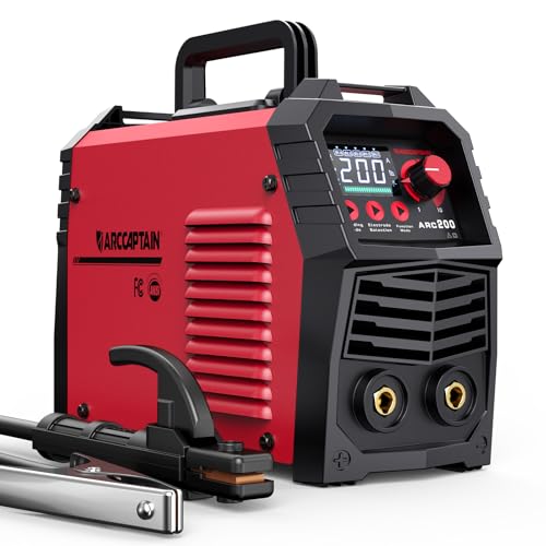
【EASY TO USE】Intelligent LED screen design, provides you with accurate data display and more choices, helps you read it easier and more clearly without taking off your helmet. Good performance on 6010, 6011, 6013 and 7018 rods. It's very suitable for outdoor maintenance, garage, farm, craft, and home DIY. Note: DO NOT power on until the screen turns off and the fan stops working!

More Powerful: Up to 205 amps with Hot Start & Arc Force,adopts IGBT Technology for more efficient and smoother arc quality. Weld continuously without interruption, significantly reducing the risk of welding rod sticking during the welding process. Compatible with most 6010, 6011, 6013 and 7018 welding rods,supports dual voltage (110V/220V). Ideal for welding stainless steel, mild steel, and other metal materials,delivering strong and durable weld joints

【200Amp Power for Home Repairs & DIY】 This 110V stick welder Adjustable Current: 20-200A. Easily weld metal materials with 0.06-0.2 inch thickness, such as cast iron, mild steel, etc. For stainless steel, use E308L-16 rods only. Includes 20 welding rods right out of the box, so you can start your first project immediately.
Safety Considerations When Using a Welding Transformer
Electrical Shock and Grounding
OSHA’s arc-welding requirements call for proper installation, a grounded machine frame where required, secure welding-circuit connections, and strict use of the manufacturer’s instructions. The work lead must be firmly attached to the work. It is not permission to clamp yourself, a building conduit, a chain, a hoist, or another unintended path into the circuit.
- Wear dry, hole-free welding gloves and dry protective clothing.
- Do not weld while standing in water or wearing wet clothing.
- Do not touch the electrode and workpiece with bare skin at the same time.
- Keep the electrode holder off conductive surfaces when it is not in use.
- Do not wrap welding cable around your body.
- Disconnect and lock out input power before authorized service.
Fire and Explosion
OSHA’s general welding requirements use a 35-foot fire-prevention radius for combustible materials and call for a fire watch in specified conditions. A required fire watch must remain for at least 30 minutes after welding ends.
Never weld on a drum, tank, pipe, wheel, or closed part that may contain flammable, toxic, or pressurized material unless it has been identified, cleaned, isolated, vented, and approved under a proper hot-work procedure. Hidden coatings, fuel residue, foam, sealers, and combustibles on the far side of a panel can ignite.
Eye, Skin, and Fume Protection
Use an approved welding helmet, safety glasses with side protection, flame-resistant clothing, leather gloves, and suitable footwear. Lens shade is selected by the process and electrode size; OSHA’s guide lists shade 10 for common 1/16- through 5/32-inch shielded-metal-arc electrodes and darker shades for larger electrodes. An auto-darkening helmet must still meet the applicable protective standard.
Keep your head out of the plume and use ventilation that controls fumes at the source. Stainless steel, plated metal, painted metal, and unknown coatings need special attention. Do not use oxygen for ventilation, and do not weld near chlorinated-degreasing vapors.
A work clamp completes the welding circuit. It does not make the welder—or the person using it—“grounded and safe.”
Real-World Applications: Welding Transformers in Action
Transformer power sources have long served farm repairs, maintenance shops, schools, light fabrication, heavy fabrication, submerged-arc systems, and other fixed installations. Their role depends on the complete machine, not the transformer alone.
For structural steel, pipelines, pressure equipment, vehicle structures, and seismic work, the power source is only one part of compliance. The base metal, filler classification, joint details, preheat, interpass temperature, heat input, welder qualification, inspection, and acceptance criteria must follow the governing drawing, code, and WPS.
Automotive high-strength steels and reinforcing bars are especially easy to damage with casual welding. Verify the material and repair procedure before applying heat. Some components must not be welded at all, and some reinforcing bar is weldable only under a qualified procedure.
Advanced Tips for Optimizing Weld Quality with Transformers
- Use the electrode data sheet. Set polarity and amperage by classification, diameter, position, and manufacturer—not by a universal rule.
- Prepare the joint to the drawing or WPS. Groove angle, root opening, land, backing, and fit-up depend on thickness, process, access, and required penetration.
- Control arc length. A long arc raises voltage and often increases spatter, porosity risk, and undercut. Keep it short and consistent unless the electrode instructions call for another technique.
- Use the correct angles. Work angle is set by joint geometry; travel angle is set by electrode type, position, puddle control, and procedure—not simply by AC versus DC.
- Confirm preheat. Preheat is not automatically 100–200°F. Material chemistry, thickness, restraint, hydrogen level, ambient conditions, and the applicable code or WPS determine whether it is needed and at what temperature.
- Track duty cycle and cable heating. Hot connectors or clamps indicate resistance or undersized components and require correction.
- Inspect between passes. Remove slag, look for undercut, porosity, incomplete fusion, and cracks, and correct the cause before covering a defect.
- Do not peen by default. Peening may be restricted or prohibited by the procedure and is not a substitute for correct heat input or stress-control planning.
- Record repeatable settings. Log machine tap or dial position, measured current when available, electrode, polarity, joint, and result.
Conclusion: Power Up Your Welds with Confidence
A welding transformer is a step-down power component built to make high welding current available at a lower voltage. In a conventional stick welder, it may supply AC directly. In a transformer-rectifier machine, additional components produce DC. The design can be rugged and dependable, but it is not automatically safer, more efficient, or suitable for every welding process.
The practical checks are simple: match the process and electrode to the output, match the input circuit to the nameplate, connect the work lead correctly, follow the duty cycle, keep the machine dry and maintained, and stop when a fault appears. Test settings on scrap, but use a qualified procedure whenever the weld affects safety or code compliance.
Frequently Asked Questions
What is the difference between a welding transformer and a regular power transformer?
Both use electromagnetic induction, but a welding transformer is designed for the unusual electrical load of an arc. A stick-welding source normally has a drooping constant-current output, thermal protection, heavy secondary conductors, welding terminals, and controls suited to repeated arc starts and short circuits. A general power transformer is not a safe substitute.
Can I convert my welding transformer to DC output?
Only when the manufacturer provides an approved conversion or a qualified welding-equipment specialist engineers and certifies the complete modification. A safe DC conversion involves more than adding a bridge rectifier; current rating, reverse voltage, heat sinking, cooling, insulation, fault protection, inductance, enclosure integrity, and output connections all matter. For most owners, buying a purpose-built AC/DC or DC machine is the safer choice.
How do I know if my welding transformer is overheating?
Common signs include a thermal-protection shutdown, repeated loss of output, an overtemperature light, abnormal fan behavior, a burning smell, smoke, discoloration, or unusually hot cables and connections. Do not judge safety from a universal case-temperature number. Stop welding, follow the cooling instructions in the manual, and obtain service if the condition returns.
Are welding transformers suitable for beginners?
Yes, when the machine is correctly installed and the beginner receives welding and safety instruction. Simple current selectors can make the controls easy to learn. However, an AC-only transformer may be harder to start with electrodes not designed for AC, and the machine’s weight and electrical requirements still need proper handling.
What is a good duty cycle for home welding projects?
Choose by the amperage and length of welds you expect to make. A 20% rating may be adequate for short repair welds because it allows two minutes of welding in a 10-minute period at the stated output. Longer beads, larger electrodes, training sessions, and repeated multi-pass welds benefit from a higher duty cycle.
Can a stick-welding transformer be used for MIG welding?
Not by itself. Most MIG welding needs a constant-voltage DC power source, a controlled wire feeder, a compatible gun, and shielding gas or self-shielded flux-cored wire. A plain constant-current AC stick transformer has the wrong output and lacks the required feeding and control system.
Can a transformer welder handle stainless steel or aluminum?
Some transformer welders can weld stainless steel with a compatible electrode and approved polarity. Aluminum requires a process, output, filler, cleaning method, and procedure suited to the alloy; many basic AC stick transformers are a poor choice. Check the welder manual and consumable data rather than assuming the maximum amperage makes the machine compatible.
Sources
- University of Central Florida — Transformers — electromagnetic induction, turns ratio, and laminated-core fundamentals
- Lincoln Electric — AC225 Product Specification — model-specific input, output, duty cycle, OCV, and weight example
- OSHA 29 CFR 1910.254 — Arc Welding and Cutting — installation, grounding, work-lead, inspection, and maintenance requirements
- OSHA 29 CFR 1910.252 — General Welding Requirements — fire prevention, PPE, ventilation, confined-space, and hot-work precautions
- Miller Electric — Safety and Scheduled Welding-Machine Maintenance — work-lead terminology, grounding, inspection, and cleaning intervals
- Lincoln Electric — Storing and Redrying Electrodes — classification-specific electrode storage and moisture-control guidance
(Word count: approximately 4,275)