When I first moved from sheet metal to 1/4-inch steel, I learned that a welder’s maximum amp number does not tell the whole story. My small 120V MIG could make a bead on quarter-inch plate, but making a bead and producing a sound joint are two different things.
The right machine depends on the welding process, joint design, position, access, required penetration, wire or electrode size, and duty cycle. A fillet weld on clean plate is easier than a complete-joint-penetration butt weld that can be reached from only one side.
This guide explains what size welder works for 1/4-inch mild steel, where a 120V machine falls short, which settings make a sensible starting point, and how to prepare and test a practice joint safely.
Quick Answer
For routine welding of 1/4-inch mild steel, choose a 240V machine that is manufacturer-rated for at least 1/4 inch. A 180- to 215-amp MIG or flux-core welder is the practical sweet spot. Stick can work with a 140- to 180-amp DC machine, while TIG is best with about 200 amps available.
Key Takeaways
- A 240V, 180- to 215-amp MIG or multiprocess welder is the most useful all-around choice for 1/4-inch mild steel.
- A 120V, 140-amp machine is marginal unless its manufacturer chart specifically includes the joint, wire, and thickness you plan to weld.
- MIG settings are normally selected by voltage and wire-feed speed, not by dialing a generic amperage value.
- Joint preparation, fit-up, position, access, and required penetration matter as much as maximum machine output.
- Safety-critical welds need an engineered detail, an applicable welding procedure, qualified workmanship, and the required inspection.

Close-up of vehicle side-mirror glass being removed.
At a Glance
| Time Required | About 30–60 minutes to prepare, weld, cool, and inspect one practice coupon; expect additional practice time. |
| Difficulty | Intermediate. Beginners should first practice beads, fillets, and joint fit-up on scrap. |
| Tools Needed | Suitable welder, correct consumable and gas, grinder, clamps, measuring tools, clean practice plate, welding helmet, safety glasses, gloves, protective clothing, and ventilation. |
| Cost | Low for a practice coupon if you already own suitable equipment; high if you must buy a 240V welder or install a compliant circuit. |
Warning: This guide is for general mild-steel practice and light fabrication. Do not use it as a welding procedure specification for trailers, buildings, lifting equipment, vehicle structures, pressure parts, roll cages, or other safety-critical work. Those jobs require the correct engineering details, material identification, applicable code, qualified procedure, and required inspection.
Amperage Basics for 1/4-Inch Steel
Amperage controls heat and deposition, but the way you select it changes with the welding process. On stick and TIG machines, you normally set welding current directly. On conventional constant-voltage MIG equipment, you set voltage and wire-feed speed; wire-feed speed has a strong effect on the current produced during welding.
The familiar “one amp per 0.001 inch” rule is only a rough TIG starting idea under limited conditions. Applying it blindly would suggest 250 amps for 1/4-inch material, even though a properly beveled mild-steel joint can often be TIG welded with less current and multiple passes. It is not a reliable machine-buying formula.
A welder’s maximum output tells you what it can reach. Its rated output and duty cycle tell you how long it can keep working there.
For regular MIG or flux-core work on 1/4-inch mild steel, a machine with roughly 180–215 amps of available output and a manufacturer rating of at least 1/4 inch is a sensible minimum. A 200- to 215-amp 240V machine gives useful headroom for fit-up variation, multiple passes, and longer work periods.
For stick welding, a 140- to 180-amp DC machine can run common 1/8-inch electrodes comfortably. For TIG, a 200-amp-class DC machine is a practical choice because quarter-inch steel can keep an air-cooled torch near its limit during long welds.
Maximum Output, Rated Output, and Thickness Rating
These three specifications are related, but they do not mean the same thing:
- Maximum output is the highest current the machine can produce. It may be available for only a short period.
- Rated output states a current, voltage, and duty cycle under specified test conditions.
- Material-thickness rating is the manufacturer’s claimed operating range for a particular process, input voltage, material, and setup.
A 215-amp machine rated at 30% duty cycle can weld at that rating for about three minutes in a ten-minute period before it needs the specified cooling time. The same machine may provide a much higher duty cycle at 150 or 160 amps.
Note: Thickness ratings usually assume a recommended joint, consumable, position, input voltage, and technique. They do not guarantee complete penetration in every joint configuration.
How the Joint Changes the Welder Size You Need
A machine that handles a 1/4-inch fillet weld may not be enough for a one-sided complete-joint-penetration groove weld. Before selecting a welder, answer these questions:
- Is the joint a fillet, lap, corner, or butt joint?
- Does the drawing require partial or complete joint penetration?
- Can you weld from both sides?
- Will the joint use a bevel, root opening, backing bar, or back-gouging?
- Is the weld flat, horizontal, vertical, or overhead?
- Is the assembly heavily restrained?
- Is the steel ordinary mild steel, high-strength steel, cast steel, or an unknown alloy?
Flat fillets are generally the easiest. Vertical and overhead joints usually need lower deposition rates and more operator control. A tight square-groove butt joint welded from one side is much harder to fuse through than a properly prepared groove with access to both sides.
Best Welding Processes for 1/4-Inch Mild Steel
MIG, flux-core, stick, and TIG can all join quarter-inch mild steel when the machine, joint, and consumable are suitable. They do not have identical power requirements or preparation needs.
| Process | Practical Machine Class | Common Consumable | Main Advantage | Main Limitation |
|---|---|---|---|---|
| MIG | 180–215A, preferably 240V | 0.035-inch ER70S-6 | Fast, clean, and beginner-friendly | Shielding gas and clean metal are important |
| Self-shielded flux-core | 180–215A class for regular 1/4-inch work | Wire approved for the required passes, such as E71T-11 | Works outdoors without a gas cylinder | Slag, fumes, spatter, and wire-specific limits |
| Stick | 140–180A DC | 1/8-inch E7018, E6011, or procedure-specified electrode | Portable and useful outdoors | More starts, slag removal, and operator skill |
| TIG | About 200A DC | 3/32-inch ER70S-2 or procedure-specified filler | Precise heat and puddle control | Slow and demanding on thick plate |
MIG Welding for 1/4-Inch Steel
MIG is my first choice for clean quarter-inch mild steel when speed and ease of use matter. A continuous wire feed makes it easier to maintain a steady arc and fill a groove without repeated electrode changes.
With 0.035-inch ER70S-6 wire and C25 gas, many 200- to 215-amp-class machines start somewhere around 20.5–22 volts and roughly 350–450 inches per minute on 240V. That is only a broad neighborhood. Use the chart inside your machine or its official parameter guide first. For example, Miller’s current Multimatic 215 PRO parameter chart provides exact voltage and wire-speed combinations by material thickness, wire, gas, and input voltage.
Do not assume every gas-shielded MIG arc is spray transfer. C25 is commonly used for stable short-circuit welding. Conventional spray transfer normally requires an argon-rich blend, enough voltage and current, suitable wire, and an appropriate welding position.
Advantages: Fast deposition, limited slag, good visibility, and an easier learning curve.
Limitations: Wind can disrupt shielding, contaminated metal causes defects, and a small gun may overheat before the power source reaches its duty-cycle limit.
Stick Welding 1/4-Inch Plate
Stick welding is useful for field repairs, outdoor work, and places where carrying a shielding-gas cylinder is inconvenient. It is more tolerant of imperfect field conditions than solid-wire MIG, but that does not make paint, oil, heavy rust, plating, or mill scale acceptable joint preparation.
For a 1/8-inch E7018 electrode, Lincoln lists approximately 90–160 amps on DC electrode positive, depending on the exact product and application. A starting point around 120–135 amps is common for flat practice joints, but the electrode package and machine chart control. Larger 5/32-inch electrodes use more current and need a machine with greater output.
E7018 is a low-hydrogen electrode that must be handled according to its package instructions and the governing procedure. For noncritical field repairs, E6011 may be selected because it runs on AC or DC and tolerates less-than-perfect conditions better, but it is not a substitute for the electrode required by a drawing or WPS.
Keep a short, controlled arc and remove every trace of slag before adding another pass. Slag trapped under a fill or cap pass can create a serious internal defect.
When to Choose TIG for Quarter-Inch Steel
TIG is best when control and appearance matter more than production speed. It works well for precise fixtures, stainless work, root passes, and jobs where the operator must control filler addition separately from the arc.
For 1/4-inch mild steel, use DC electrode negative, 100% argon, and a tungsten size approved for the planned current. A 3/32-inch 2% lanthanated tungsten is a common choice in this range. The current may land around 160–190 amps for a properly prepared joint, but fit-up, torch rating, position, and travel speed can move the setting substantially.
An air-cooled 150-amp torch is easy to overheat during sustained quarter-inch work. A larger air-cooled torch, a water-cooled system, or planned cooling breaks may be needed.
Flux-Core Welding for Outdoor Work
Self-shielded flux-core is useful where wind would make gas-shielded MIG unreliable. E71T-11 is a self-shielded classification, but polarity, wire diameter, pass limits, and recommended thickness must come from the exact wire datasheet. Many E71T-11 wires use DC electrode negative.
Gas-shielded wires in the E71T-1 family require external shielding gas. The exact classification may include a C or M suffix that identifies the gas used for classification. Do not run a gas-shielded wire without the gas specified by its manufacturer.
Flux-core can penetrate well, but it does not excuse welding through paint, oil, heavy rust, or unknown coatings. Clean the joint and remove slag fully between passes.
Recommended Welder Sizes and Current Models for 1/4-Inch Steel
For a new purchase, I would normally choose a 240V machine with at least 180–215 amps of usable output and a manufacturer rating that includes 1/4-inch steel. Extra output is useful, but a stronger duty cycle at the current you actually use is often more valuable than a larger maximum number.
| Welder Model | Input and Output | Processes | Fit for 1/4-Inch Steel | Price Note |
|---|---|---|---|---|
| Eastwood MP140i | 120V; MIG up to 140A; stick up to 75A; MIG rated 90A at 30% | MIG, flux-core, DC TIG, stick | Not my first choice. Better for light fabrication and material near its published range. | Compare the current package and included accessories directly with the manufacturer. |
| Lincoln Power MIG 215 MPi | 120/230V; 20–220A on 230V; rated 215A at 30% | MIG, flux-core, DC TIG, stick | Strong all-around fit for quarter-inch mild steel on 230V. | One-Pak and accessory packages can differ substantially. |
| Miller Multimatic 215 PRO | 120/240V; 20–230A; rated 215A at 30% and 160A at 60% on 240V | MIG, pulsed MIG, flux-core, DC TIG, stick | Excellent current 215-class option; manufacturer-rated through 3/8-inch steel on 240V. | Newer 2026 model; compare base, cart, and TIG packages. |
| ESAB Rebel EMP 205ic AC/DC | 120/230V regional model; approximately 205A maximum class | MIG, flux-core, stick, DC TIG, AC TIG | Suitable when AC TIG for aluminum is also important. Confirm the U.S. regional datasheet. | Typically a higher-cost all-process package. |
| Hobart Handler 190 | 230V; 25–190A; rated 130A at 30% | MIG and flux-core | Capable light-fabrication choice, but less duty-cycle headroom than newer 215A machines. | Simple single-process machines may cost less than comparable multiprocess units. |
The older Miller Multimatic 215 remains a capable machine, but the newer 215 PRO is the fresher comparison for buyers. The 2026 model adds a 215A-at-30% rating and a 160A-at-60% rating on 240V.
Pro Tip: Compare duty cycle at 150–180 amps, not only maximum output. That range is where many quarter-inch multipass jobs spend most of their time.
Products Worth Considering

7-IN-1 Welder: The 215A multi-process Bestarc mig welder combines Gas MIG, Flux Core MIG, Aluminum MIG, Lift TIG, Stick, Spot, and Spool Gun MIG in one unit (TIG torch and spool gun need to be purchased separately). In addition to mild steel and stainless steel, the MIG welder is specifically designed for aluminum welding, utilizing both a standard MIG torch and a spool gun to ensure consistent wire feeding and stable arc performance. Perfect for home DIY, garage projects, outdoor repairs, and farm equipment work.

Dyna-Pulse MIG Welding: Now with Dyna-Pulse MIG, this welder supports mild steel, stainless steel, aluminum (with spool gun), and flux-cored wire; powered by continually upgradable USB-enabled software
Can a 120V Welder Handle 1/4-Inch Steel?
Sometimes, but “can strike an arc on it” is not the same as “is a dependable quarter-inch machine.” A 120V unit may make a multipass fillet or repair when the manufacturer’s chart allows that setup, but it usually has less voltage, output, wire-size capacity, and duty-cycle headroom than a 240V machine.
A small 120V unit is especially limited when the joint needs full penetration, the fit-up is poor, the weld is vertical or overhead, or the work is heavily restrained. Some dual-voltage machines are advertised for 1/4 inch only when connected to 240V.
Do not assume that adding more passes makes an undersized setup acceptable. Each pass must fuse into the base metal and previous bead. Multiple cold passes can create a larger defective weld rather than a stronger one.
Electrical Circuit, Extension Cord, and Generator Requirements
Use the input circuit listed on the machine nameplate and in its manual. Full output from a 200- or 215-amp-class machine normally requires its 230/240V input connection. Circuit conductor size, breaker size, receptacle, duty-cycle allowances, and local code requirements should be handled by a qualified electrician.
A long or undersized extension cord can cause voltage drop, poor arc performance, overheating, and equipment damage. Use an extension cord only when the manufacturer permits it, and follow the specified conductor size and maximum length.
Generator sizing is also model-specific. The generator must provide the required continuous power and acceptable voltage regulation, not merely a large advertised surge number. Check the welder manual before connecting it to a portable generator.
Warning: Do not alter plugs, use improvised adapters, or share an overloaded circuit to obtain more welding output. Electrical installation must follow the welder instructions and applicable electrical code.
How to Set Up Your Welder for 1/4-Inch Steel
Start with the machine’s official chart. Then fine-tune on clean scrap of the same thickness, joint type, position, and material as the real work.
MIG Setup
- Use DCEP for ordinary solid-wire steel MIG.
- Install the drive roll, liner, contact tip, and gun rated for the selected wire.
- For a common setup, use 0.035-inch ER70S-6 wire and C25 shielding gas.
- Set gas flow according to the machine and torch instructions. A range near 20–30 CFH is common in still indoor air, while some current manufacturer charts specify 25–35 CFH.
- Keep the work connection on clean metal and as close to the weld area as practical.
- Maintain the contact-tip-to-work distance recommended for the transfer mode and wire.
Do not aim a portable fan across the arc. It can pull shielding gas away from the puddle. Position local exhaust so it captures fumes without disturbing gas coverage.
Stick Setup
- Match polarity to the exact electrode. Many E7018 and E6010 products use DCEP, while E6011 can run on AC or DC.
- Select current by electrode diameter, position, and manufacturer range.
- Keep low-hydrogen electrodes dry and handle them according to the package, WPS, and code requirements.
- Remove all slag before the next pass.
TIG Setup
- Use DCEN for ordinary steel GTAW.
- Use 100% argon and a torch, cable, collet, tungsten, and cup rated for the current.
- Grind the tungsten in the lengthwise direction with a dedicated clean wheel.
- Use a foot pedal or remote when practical so heat can be reduced near the end of the weld.
Joint Preparation Tips for Strong 1/4-Inch Steel Welds
Preparation determines whether the arc can reach the joint root. Remove paint, oil, plating, heavy rust, moisture, and mill scale from the weld zone and work-clamp location. Use a clean grinder, suitable solvent, or dedicated wire brush, and allow flammable cleaners to evaporate fully before welding.
For a practice butt joint intended to show root fusion, a common starting design is a 60-degree included groove made by beveling each plate about 30 degrees. A small root face and controlled root opening help the arc reach the root. That is a practice configuration, not a universal structural detail.
Lap and T-joints still need clean, tight fit-up and adequate access to the root. Tack the assembly securely and verify alignment before making long welds.
When Preheat Is Needed
Do not automatically preheat every piece of quarter-inch mild steel. Preheat depends on the steel grade and carbon equivalent, material thickness, hydrogen level, joint restraint, ambient temperature, heat input, and governing procedure.
For ordinary noncritical mild-steel practice coupons, clean and dry material at a suitable shop temperature may need no added preheat. For structural, high-strength, heavily restrained, cold, unknown, or repair material, follow the WPS, steel specification, or applicable code. Lincoln’s preheat guidance explains why controlling cooling rate and hydrogen can matter.
Step-by-Step Guide to Welding a 1/4-Inch Butt-Joint Practice Coupon
This example uses flat-position MIG on two mild-steel coupons. It is designed for practice and destructive testing, not as a qualified procedure for a load-bearing part.
- Identify the metal: Use known weldable mild-steel coupons. Do not practice on plated, galvanized, painted, fuel-exposed, or unknown metal.
- Prepare the groove: Bevel each plate to create an included groove near 60 degrees. Leave a small, consistent root face and root opening suitable for the selected procedure.
- Clean the joint: Grind the groove faces and nearby surfaces to clean metal. Remove dust and allow any approved cleaner to evaporate.
- Fit and tack: Clamp the plates flat with consistent root spacing. Tack the ends and center, then confirm that the joint has not pulled out of alignment.
- Set the machine: Install 0.035-inch ER70S-6 wire, DCEP polarity, and C25 gas. Begin with the manufacturer’s 1/4-inch chart setting rather than a generic amperage number.
- Run the root pass: Hold a steady 10–15-degree push angle unless the machine or procedure specifies otherwise. Watch both groove faces and maintain a consistent travel speed.
- Inspect and clean: Stop if the bead shows severe undercut, porosity, incomplete tie-in, or unstable arc behavior. Clean the pass before continuing.
- Add fill passes: Use controlled stringer beads or the weave width allowed by the procedure. Tie into both groove faces without trapping valleys or rolling over the toes.
- Run the cap: Finish with an even cap that covers the groove and blends into the plate without excessive reinforcement or undercut.
- Cool naturally: Let the coupon cool in still air. Do not quench it unless a qualified procedure specifically requires that treatment.
- Test the coupon: Perform visual inspection, then cut and bend or macroetch the coupon using a recognized practice method to check fusion through the joint.
It took me several coupons to make the root, fill, and cap behave consistently. That practice was far more useful than trying to prove a setup on the finished project.
How to Inspect a Practice Weld
Begin with visual inspection under good light. Look for:
- Cracks, including small crater cracks
- Visible porosity
- Undercut at the weld toes
- Overlap or cold lap
- Incomplete tie-in between passes
- Excessive reinforcement
- Arc strikes outside the joint
- Distortion or misalignment
Visual inspection cannot prove internal fusion. For a practice coupon, cut sections across the weld, polish the face, and use an appropriate macroetch procedure, or prepare a controlled bend specimen. Dye penetrant can reveal some surface-breaking indications, but it does not prove root penetration or internal fusion.
Note: A hammer blow, successful tow, or good-looking bead is not an engineering or code acceptance test.
Filler Rod and Wire Selection for 1/4-Inch Steel
The filler must match the base metal, process, position, mechanical requirements, and governing procedure.
MIG: ER70S-6 is a common mild-steel solid wire with deoxidizers that help it handle ordinary mill scale better than some alternatives. A 0.035-inch diameter is a practical match for many 180- to 215-amp machines.
Self-shielded flux-core: E71T-11 is commonly used without external gas. Confirm whether the exact wire allows the number of passes and thickness required. Follow its polarity and storage instructions. My flux-core gas and no-gas guide explains the basic distinction.
Gas-shielded flux-core: E71T-1-family wires require the shielding gas stated by the manufacturer. Do not substitute C25, 100% CO₂, or another blend unless the wire’s classification and datasheet permit it.
Stick: E7018 is widely used where low-hydrogen weld metal and good mechanical properties are required. E6011 is useful for many repair situations, but the drawing or WPS controls filler selection for critical work.
TIG: ER70S-2 is a common mild-steel filler. A 3/32-inch rod is useful for quarter-inch work, though smaller rod may offer better control on the root.
Store all consumables clean and dry. Low-hydrogen electrode exposure and rebaking rules are product- and code-specific; do not improvise oven temperatures.
Choosing the Right Shielding Gas
For solid-wire MIG on mild steel, 75% argon and 25% CO₂, usually called C25, gives a stable short-circuit arc with moderate penetration and manageable spatter. Miller’s MIG shielding-gas guide explains the common choices.
One hundred percent CO₂ generally costs less and can provide strong penetration, but it produces a harsher arc and more spatter. Argon-rich mixtures such as 90/10 may support spray or pulsed-spray transfer when the machine, wire, current, voltage, and position are suitable.
For TIG welding ordinary steel, use 100% argon. A starting flow near 15–20 CFH is common, but cup size, torch geometry, drafts, and gas-lens use can change the requirement. More flow is not always better; excessive flow can pull air into the shielding envelope.
See my guide to MIG shielding gas for mild steel for a longer comparison.
Safety Considerations When Welding Quarter-Inch Plate
Quarter-inch plate stores more heat than sheet metal and can remain hot long after the color disappears. Wear flame-resistant clothing, welding gloves, safety glasses under the helmet, high-top leather footwear, and hearing protection where grinding or process noise requires it.
Select the filter shade by process and current. OSHA lists shade 10 as the minimum for many GMAW, FCAW, and higher-current GTAW operations in the range commonly used on quarter-inch material. Use a darker shade when needed for comfort while maintaining a clear view of the puddle.
Use ventilation or local exhaust appropriate to the material and process. Welding fumes come from the wire or electrode, base metal, coatings, surface contaminants, and reactions in the arc. Position extraction to pull contaminants away from your breathing zone without stripping shielding gas from the weld.
Keep combustible materials away from sparks and slag. Use guards where hazards cannot be moved, maintain a suitable fire extinguisher, and inspect the area after welding for hidden smoldering material.
Secure gas cylinders upright with a chain or approved restraint. Argon and CO₂ are not fire-starting gases, but cylinders contain high pressure and a leak can displace oxygen in a poorly ventilated area. Protect valves and transport cylinders with the regulator removed and valve cap installed when required.
Keep gloves, clothing, the work area, and electrode holders dry. The work lead is part of the welding circuit; it is not a substitute for the electrical grounding and bonding required by the equipment installation.
Warning: Never weld a tank, drum, wheel, pipe, container, or enclosed part that has held fuel, solvent, refrigerant, gas, oil, or another hazardous substance unless it has been evaluated and prepared under a qualified hot-work procedure. Never weld unknown coatings or galvanized metal without controlling the coating and fume hazard.
For structural-steel work, use the edition and amendments required by the contract or authority having jurisdiction. AWS currently lists AWS D1.1/D1.1M:2025-AMD1 for structural steel.
Common Mistakes and Quick Fixes
Undercut: Excessive voltage, long arc length, poor angle, or travel that is too fast can wash away the toe. Return to the manufacturer’s chart and correct one variable at a time.
Porosity: Check for drafts, leaks, blocked nozzle passages, excessive stickout, contamination, wet consumables, or improper gas flow. Grind contaminated metal clean rather than blowing debris into the joint.
Lack of fusion: Increase access to the root with proper joint preparation, correct travel speed and angle, and machine settings within the manufacturer’s range. Confirm the result with a cut-and-etch or bend coupon, not a file.
Cold lap or overlap: The puddle is rolling onto the plate without fusing at the toe. Reduce deposition, improve angle, increase travel speed, or adjust heat within the approved range.
Slag inclusions: Clean every flux-core or stick pass fully. Avoid deep valleys and excessively wide weaving.
Warping: Use balanced tack placement, shorter weld sequences, back-stepping where suitable, clamps, preset, and alternating sides. Do not over-weld the joint.
Burnback or bird-nesting: Inspect contact-tip size, liner condition, drive-roll type, spool tension, gun-cable bends, and drive-roll pressure.
Thermal overload: Stop welding and let the machine cool according to its manual. Leave the power on if the manufacturer instructs you to do so for fan cooling. Do not aim dusty shop fans into the machine or across the arc.
Pros and Cons of Different Welder Power Classes
120V welders near 140A: Easy to power and useful for light repairs, but limited for routine quarter-inch work. They may need small wire, multiple passes, and long cooling periods.
240V welders near 180–200A: A practical value class for 1/4-inch MIG, flux-core, or stick work. Check the rated output because some machines reach their maximum only at a low duty cycle.
240V welders near 200–215A: The best all-around range for most garages and small fabrication shops working regularly with quarter-inch plate.
Machines above 250A: Useful for higher deposition rates, larger wire, thicker material, and stronger duty cycle. They are not automatically necessary for 1/4-inch steel.
Multiprocess machines: Convenient when you genuinely need MIG, stick, and TIG. A simpler single-process MIG machine may provide better value if MIG is all you use.
Products Worth Considering

POWERFUL 6-IN-1 MIG WELDER: The multi-process welding machine that included Gas/Solid Wire MIG(GMAW), Gasless Flux Core MIG(FCAW), Stick/MMA, Spot welding, Lift TIG, spool gun connector optional (tig gun and spool gun not included). Suitable for all kinds of welding requirements .023”/.030”/.035” solid wire, .030”/.035” flux core wire, .035”/.040” aluminum wire. (.023”, .040” rollers need to buy separately)
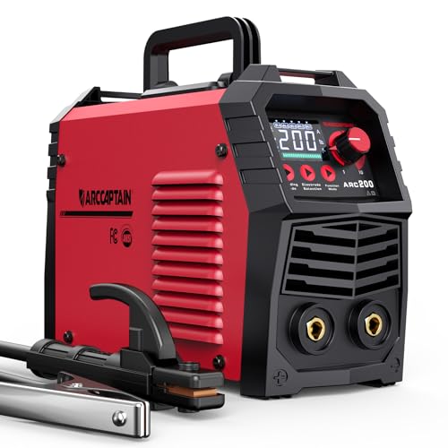
【EASY TO USE】Intelligent LED screen design, provides you with accurate data display and more choices, helps you read it easier and more clearly without taking off your helmet. Good performance on 6010, 6011, 6013 and 7018 rods. It's very suitable for outdoor maintenance, garage, farm, craft, and home DIY. Note: DO NOT power on until the screen turns off and the fan stops working!

[𝟕-𝐈𝐍-𝟏 𝐌𝐔𝐋𝐓𝐈𝐏𝐑𝐎𝐂𝐄𝐒𝐒 𝐖𝐄𝐋𝐃𝐄𝐑]: The RB360 takes on Gas MIG, Flux Core, Stick, LIFT TIG, Plasma Cutting, Spot Welding, and Aluminum welding without breaking a sweat. Flip between functions quickly to shift from precision thin metal repairs to tough outdoor structural work. For DIYers working out of their garage and farmers handling equipment maintenance, this welder covers almost every task you could ask of it.
Real-World Applications
Quarter-inch mild steel is common in machine bases, brackets, gates, equipment mounts, shop fixtures, and some trailer components. The correct process depends on access, environment, required weld size, and the governing design.
MIG is efficient for clean shop-built frames and brackets. Stick is useful for outdoor repairs and locations where shielding gas is inconvenient. Self-shielded flux-core works well outdoors when the exact wire is approved for the joint. TIG can produce precise, attractive work but is usually slower than necessary for ordinary fabrication.
Vehicle frames, trailer tongues, suspension mounts, hitches, roll cages, lifting points, and highway components are not ordinary practice projects. Verify the material and follow the vehicle, component, or equipment manufacturer’s repair procedure where one exists. A personal road test does not prove fatigue life or load capacity.
Advanced Tips for Better Quarter-Inch Welds
Record working settings: Keep notes on machine, input voltage, wire, gas, voltage, wire speed, stickout, joint, position, and travel technique. A complete record is more useful than writing down amperage alone.
Control interpass temperature: Let the procedure or material specification set the minimum and maximum. Excessive interpass temperature can reduce properties and increase distortion.
Use stringers when possible: Stringer beads make it easier to control heat and inspect tie-in. If weaving is allowed, stay within the width permitted by the procedure and consumable manufacturer.
Do not improvise post-weld heat treatment: Heating or peening a weld is not a universal stress-relief method. Some procedures limit or prohibit peening, and post-weld heat treatment must be engineered for the material and application.
Watch the gun rating: A compact machine may produce 200 amps while its supplied gun has a lower continuous-duty rating. A hot handle, discoloration, or repeated contact-tip failure can indicate that the gun needs cooling time or a higher-rated replacement.
Maintenance for Reliable 1/4-Inch Welding
Disconnect input power before internal inspection or maintenance unless the manual specifically requires the machine to be energized for a test performed by a qualified person.
For MIG and flux-core equipment:
- Inspect the contact tip, nozzle, diffuser, liner, drive roll, and work connection.
- Use a V-groove roll for ordinary solid wire and the manufacturer-recommended knurled roll for flux-core.
- Keep the gun cable as straight as practical during feeding.
- Remove dust from the machine only by the method and schedule in the owner’s manual.
- Do not lubricate drive components unless the manufacturer specifically instructs it.
For stick and TIG equipment, inspect electrode holders, torch parts, gas hoses, connectors, and cable insulation. Replace damaged leads rather than taping over serious cuts or exposed conductors.
Commercial equipment should follow a documented preventive-maintenance schedule based on operating hours, environment, and manufacturer guidance.
Conclusion: Choose Capacity, Not Just a Maximum Amp Number
For most people who regularly weld 1/4-inch mild steel, a 240V MIG or multiprocess machine in the 180- to 215-amp class is the right starting point. It gives more useful voltage, wire-size capacity, and duty-cycle headroom than a small 120V machine.
MIG is the easiest process for clean shop work, stick is strong for portable outdoor use, self-shielded flux-core handles wind without a gas cylinder, and TIG gives the most precise control. Whichever process you choose, the joint design, preparation, position, consumable, and test method decide whether the finished weld is sound.
Before welding the real part, make a coupon from the same material and thickness. Record the settings, cut or bend the coupon, and correct the setup before trusting it on a finished project.
Frequently Asked Questions
What amperage is best for single-pass welding on 1/4-inch steel?
There is no process-neutral amperage. A 1/8-inch E7018 stick electrode commonly runs within about 90–160A, while MIG settings are selected by voltage and wire-feed speed and may produce current near the machine’s upper range. A complete-penetration single pass also depends on joint design and transfer mode. Follow the machine and consumable charts.
Can a 120V welder handle 1/4-inch steel projects?
A few manufacturer-approved setups may make multipass quarter-inch joints on 120V, but a typical 140A machine is marginal. It is not the preferred choice for full-penetration, vertical, overhead, heavily restrained, or safety-critical work. A 240V machine rated for at least 1/4 inch is more dependable.
Is a 180-amp welder enough for 1/4-inch steel?
Often, yes. A capable 180A 240V MIG or stick machine can handle many quarter-inch joints when its manufacturer approves the thickness and the joint is prepared correctly. A 200- to 215-amp model provides more headroom and usually a better duty cycle for repeated work.
MIG or stick: which is easier for beginners on quarter-inch plate?
MIG is generally easier because the wire feeds continuously and there is no slag to remove with solid wire. Stick is valuable outdoors and for portable repairs, but controlling arc length, restarts, electrode angle, and slag takes more practice.
Do I need to bevel 1/4-inch steel before welding?
Not every fillet or lap joint needs a bevel. A butt joint that requires deep or complete penetration often needs a groove, root opening, backing, access from both sides, or another approved detail. Use the drawing, WPS, or a suitable practice-joint design rather than beveling by guesswork.
How do I avoid cracks in welds on 1/4-inch mild steel?
Identify the steel, remove contaminants and moisture, use the correct filler, control fit-up and restraint, fill craters, and follow any required preheat and interpass limits. Do not apply blanket preheat temperatures or quench the weld unless an approved procedure requires it.
What duty cycle do I need for welding 1/4-inch steel all day?
For frequent fabrication, look for a strong duty cycle around the current you will actually use, often 150–180A. A 30% rating means about three minutes of welding in a ten-minute period at that rated output. A 60% rating means about six minutes. Production work may justify a higher-capacity machine.
What breaker size do I need for a 1/4-inch-capable welder?
Use the branch-circuit requirements in the exact welder manual and nameplate data. Do not select a breaker from output amperage alone. Conductor size, receptacle, duty-cycle allowances, voltage, local code, and installation conditions all matter, so a qualified electrician should install or verify the circuit.
Sources
- Miller Multimatic 215 PRO Parameter Chart — process-specific voltage, wire-speed, gas, polarity, TIG, and stick starting settings.
- Miller Multimatic 215 PRO Specification Sheet — 2026 output, duty cycle, input voltage, and material-capacity data.
- Lincoln Power MIG 215 MPi Product Specifications — rated output, duty cycle, output range, and input requirements.
- Lincoln Excalibur E7018-1 MR — diameter-specific electrode current and polarity information.
- OSHA Welding, Cutting, and Brazing Standards — ventilation, fire prevention, PPE, electrical, and compressed-gas safety requirements.
- AWS D1.1/D1.1M Structural Welding Code—Steel — current structural-steel welding code and amendment information.