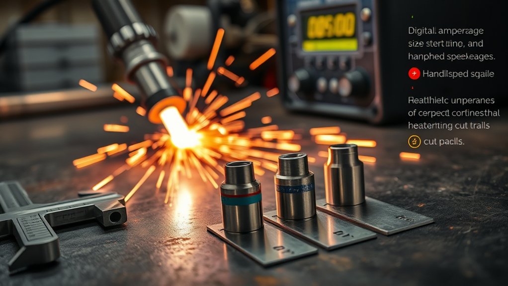
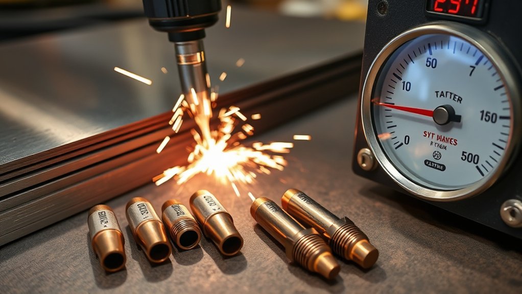
Choosing the right plasma tip starts with matching nozzle orifice to material thickness, amperage, and gas pressure per OEM cut charts. You’ll set tip size by the machine’s rated current (e.g., 20A for 0.6 mm at ~50–55 psi; 50A for 1.0 mm at ~65–75 psi), then tune standoff and speed to control kerf and dross. Get this wrong and you burn consumables fast. Next, let’s map tip sizes to thickness and speed with tolerances.
Matching Tip Size to Material Thickness
Start by matching tip amperage to material thickness and setpoints. You’ll improve cut quality and consumable life when tip selection reflects material compatibility and validated parameters.
For 0.6 mm (0.025 in) stock, use a 20 A tip at 15–20 A and 50–55 psi. For up to 0.8 mm (0.030 in), step to a 30 A tip at 21–30 A and 55–60 psi. At 0.9 mm (0.035 in), a 40 A tip with 31–40 A and 65–70 psi maintains kerf stability.
For 1.0 mm (0.040 in), specify a 50 A tip at 41–50 A and 65–75 psi. At 1.1 mm (0.044 in), a 60 A tip with 51–60 A and 65–75 psi sustains arc density and minimizes dross.
Confirm your torch’s rated pressure window and verify orifice geometry against OEM charts to avoid over-energizing smaller tips. If surface coatings or alloys vary, prioritize conservative amperage within the stated range, validate on scrap, and document your qualified settings.
Amperage Ranges for Common Tip Orifice Sizes
For each common orifice size, you’ll match tip size to a defined amperage band and corresponding gas pressure.
For example:
0.6 mm (20 A tip) runs 15–20 A at 50–55 psi;
0.8 mm (30 A) runs 21–30 A at 55–60 psi;
0.9 mm (40 A) runs 31–40 A at 65–70 psi;
1.0 mm (50 A) runs 41–50 A at 65–75 psi.
Higher-capacity tips—1.2 mm (70 A) and 1.3 mm (80 A)—run 61–70 A and 71–80 A respectively, both at 75–80 psi.
Tip Size to Amps
Two factors define plasma tip selection: orifice size and the amperage you intend to run. Match the tip to the current window to maintain arc stability, cutting efficiency, and tip longevity.
Use a 20‑amp tip when operating 15–20 A. Step up to a 30‑amp tip for 21–30 A. For mid‑range output, a 50‑amp tip with a 1.0 mm (.040) orifice supports 41–50 A. A 60‑amp tip, producing a nominal 1.1 mm (.044) kerf, runs correctly at 51–60 A.
When you need higher output, select an 80‑amp tip with a .051 in orifice for 71–80 A. Staying within these amperage windows limits double‑arcing, preserves consumables, and yields predictable kerf geometry and edge quality aligned with process specifications.
Pressure Ranges by Size
Although amperage and orifice size set the process window, gas pressure must track tip size to stabilize the arc, control jet velocity, and protect consumables.
Use these benchmarks: 20 A tips (0.6 mm/.025) run 15–20 A at 50–55 psi; 30 A tips (0.8 mm/.030) run 21–30 A at 55–60 psi. For 40 A tips (0.9 mm/.035), target 31–40 A at 65–70 psi. A 50 A tip (1.0 mm/.040) operates 41–50 A at 65–75 psi. Higher-output tips—70 A (1.2 mm/.047) and 80 A (1.3 mm/.051)—cover 61–80 A at 75–80 psi.
Verify inlet supply and perform pressure adjustments under flow. Monitor cut face, dross, and kerf angle to fine-tune.
Prioritize tip maintenance: keep orifices round, clean, and aligned; replace eroded nozzles to maintain calibrated pressure-velocity balance.
Cutting Speed Considerations by Tip and Metal
A correct cutting speed depends on metal type, thickness, and the amperage-tip pairing, and you should target data-driven IPM values to control kerf and dross.
For each material type, validate speed against amperage and tip size. Manual cutting typically lands near 10–15 IPM, but higher amperage (with the matching tip orifice) lets you move faster while preserving cut quality. A larger tip, such as 1.3 mm for an 80 A torch, supports thicker sections and higher travel rates; a smaller tip favors thin sheet, tighter detail, and slower speeds.
1) Select amperage and tip: Use the maximum recommended amperage for the thickness; match the tip to the amp rating to stabilize the arc and increase cutting speed.
2) Set travel speed by thickness: Start at charted IPM and adjust until dross is minimal; heavy dross usually means you’re too slow.
3) Validate by metal: Steel tolerates higher speeds than stainless; aluminum often requires a slight reduction to maintain edge quality.
Kerf Width and Tip Size Relationships
You should tie nozzle size directly to kerf, material, amps, and pressure using quantified targets.
For example, a 20 A tip typically yields ~0.6 mm kerf, 50 A ~1.0 mm, and 70 A ~1.2 mm on steel, while copper often needs ~2x the amperage for the same thickness, widening kerf with the same nozzle.
Set gas pressure to manufacturer specs to maintain a stable arc column; overpressure broadens kerf, underpressure destabilizes it.
Nozzle Size vs. Kerf
Two variables drive kerf in plasma cutting: nozzle (tip) orifice and current. You control nozzle performance and kerf quality by matching orifice size to amperage. Larger orifices carry higher current but widen kerf: a 0.6 mm (20 A) tip typically yields ~1.5 mm kerf, while a 1.0 mm (50 A) tip produces ~2.5 mm.
Keep tip size consistent to stabilize geometry, minimize dross, and maintain finish.
1) Select by thickness: choose the smallest orifice that sustains the required current for full penetration without stalling.
2) Correlate amps and kerf: expect wider kerf as amperage rises; copper often needs roughly 2× the amps of steel at equal thickness.
3) Verify cut data: confirm nozzle size, rated current, and target kerf in your procedure sheet; record actual kerf, adjust orifice or current to meet tolerance.
Material, Amps, Pressure
Three linked variables govern kerf and cut quality in plasma cutting: material, amperage, and gas pressure.
You should size the tip to the amperage and the material’s conductivity. A 20 amp tip (0.6 mm) supports 15–20 A; a 50 amp tip (1.0 mm) suits 41–50 A. Kerf expands with tip size: a 60 A tip yields about 1.1 mm kerf.
Pressure must rise with amperage—use 55–60 psi for 30 A tips and 75–80 psi for 70 A tips—to stabilize the jet and minimize bevel.
Match amps to thickness, then select the tip and pressure accordingly. For copper, plan roughly 2× the amps versus steel, which drives larger tips and wider kerf.
Apply disciplined tip maintenance and consistent cutting techniques to maintain dimensional accuracy.
Pierce Height and Standoff Best Practices
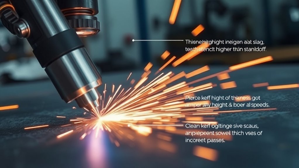
Precision starts at the arc: set pierce height to 1.5–2.0× the cutting height to shield consumables from the molten pit and upward gusher during initiation, then shift to a 1/16–1/8 in standoff for the cut to optimize edge quality and minimize dross.
Set pierce height 1.5–2× cut height, then hold 1/16–1/8 in standoff to protect consumables and cut clean.
You’ll control energy density and protect the nozzle by managing pierce height and standoff distance with the same rigor you apply to amperage and travel speed. Incorrect torch-to-work distance skews the plasma column, driving bevel and increasing rework.
Use a consistent routine:
1) Verify torch height control zero, then program pierce at 1.5–2.0× cut height; hold until the arc fully penetrates and the puddle clears.
2) Index to a 1/16–1/8 in standoff before motion; maintain it through corners to keep kerf width and angularity within spec and suppress dross.
3) Audit cut coupons: look for symmetric edge lag lines and minimal top spatter; if bevel increases, re-qualify height.
Correct setup extends consumable life, stabilizes arc voltage feedback, and shortens cycle time by reducing secondary grinding.
Gas Pressure Settings by Tip and Amps
With torch height locked in, you’ll set gas pressure to match tip size and amperage so the jet maintains a stable, constricted arc and proper kerf evacuation. Calibrate at the regulator with flowing air, then verify dynamic pressure at the torch. For peak performance, pair each tip with its specified pressure window: 20 A tips run 50–55 psi at 15–20 A; 30 A tips run 55–60 psi at 21–30 A; 40 A tips run 65–70 psi at 31–40 A; 50 A tips run 65–75 psi at 41–50 A; 70 A tips run 75–80 psi at 61–70 A. Stay within these bands to maintain jet velocity, kerf cleanliness, and dross control.
| Tip (A) | Gas Pressure (psi) | Thickness (mm/in) |
|---|---|---|
| 20 | 50–55 | 0.6 / .025 |
| 30 | 55–60 | 0.8 / .030 |
| 40 | 65–70 | 0.9 / .035 |
If arc wanders or bevel increases, adjust gas pressure in 2–3 psi increments while holding amperage constant.
Consumable Wear: When to Change Nozzle and Electrode
Discipline starts at the torch: monitor consumable wear and change parts before cut quality degrades. You’ll hold tolerance only if you treat consumables as controlled items. Inspect the nozzle orifice; any ovality, keyholing, or spatter adhesion justifies immediate nozzle replacement.
Pair it with electrode maintenance—swap both together to prevent mismatched wear that drives taper, dross, and arc instability.
Adopt a data-driven cadence:
1) Visual criteria: Replace electrodes at first visible pitting on the hafnium insert; replace nozzles when the orifice edge loses symmetry or shows burnback.
2) Operating factors: Increase inspection frequency for thick plate, high duty cycles, moisture in air supply, or inconsistent torch height—these accelerate erosion and pitting.
3) Scheduling: Log pierces, arc-on time, and material mix; set thresholds (e.g., max pierces per set) and verify with cut coupons for kerf width and bevel.
Change nozzle and electrode simultaneously. Track results; if cut quality shifts, adjust intervals, not standards.
Brand Cut Charts vs. Universal Guidelines
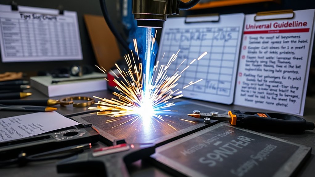
Consumable control sets the baseline; settings lock in the result. Use brand cut charts first—Hypertherm and peers validate amperage, arc voltage, pierce height, cut height, travel speed, and gas pressure by material and thickness to standardize cut quality.
Those datasets factor nozzle orifice geometry, swirl ring flow, and power‑supply ramp profiles, so you’ll hit performance optimization faster and with less trial.
Universal guidelines are useful when documentation’s missing, but they generalize across machines with different flow curves and arc densities. Expect variance in kerf, bevel angle, and dross.
Universal guidelines help when docs are missing—but machines vary, so anticipate kerf, bevel, and dross differences.
When results drift, revert to the manufacturer’s chart to re-baseline amperage, speed, and pressure by tip size.
Match tip size to application: larger orifices carry higher current but widen kerf; smaller orifices tighten kerf at lower amperage.
Validate by test coupons: record kerf width, surface roughness, top/bottom edge rounding, and dross grams per meter.
Iterate between brand charts and universal baselines to refine settings for your machine and material.
Quick Reference: Tip Sizes From 20A to 80A
Five common tip sizes cover most light industrial cutting, and each pairs a specific orifice, amperage band, and gas pressure window for stable arc density.
Use this quick reference to align tip selection strategies with orifice design considerations and your target current.
1) 20–30 A class
- 20A tip: 0.6 mm (.025) orifice, 15–20 A, 50–55 psi. Choose for thin-gauge material, tight kerf, low heat input.
- 30A tip: 0.8 mm (.030) orifice, 21–30 A, 55–60 psi. Balances cut speed with edge quality on light plate.
2) 31–50 A class
- 40A tip: 0.9 mm (.035) orifice, 31–40 A, 65–70 psi. Improves arc stiffness for moderate thickness.
- 50A tip: 1.0 mm (.040) orifice, 41–50 A, 65–75 psi. Raises throughput while maintaining acceptable kerf.
3) 71–80 A class
– 80A tip: 1.3 mm (.051) orifice, 71–80 A, 75–80 psi. Use for higher deposition removal and faster travel.
Match amperage setpoint to the tip’s rated band; don’t overdrive small orifices.
Verify supply pressure at the torch under flow to maintain arc constriction and consistent cut geometry.
Frequently Asked Questions
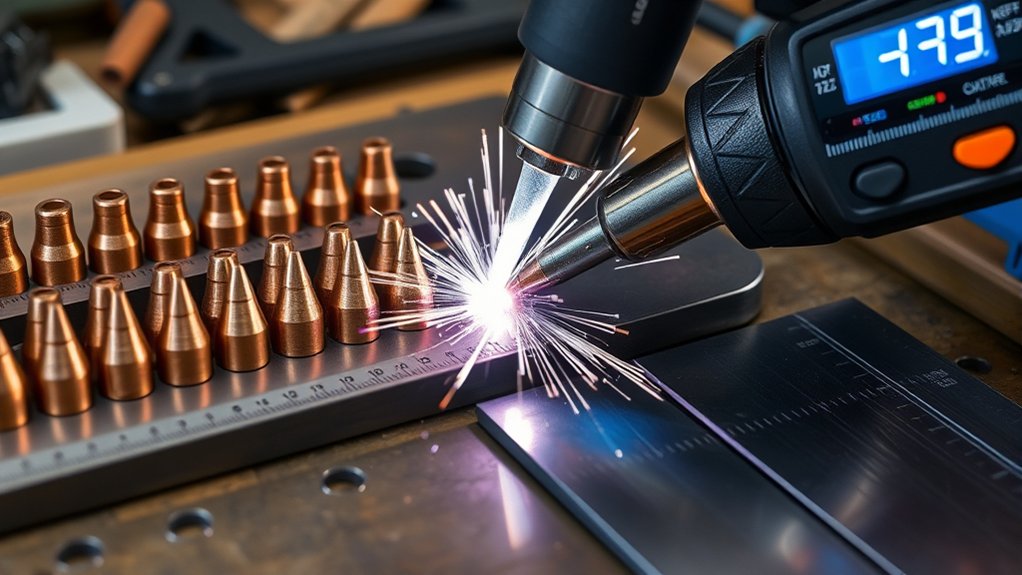
How Do Tip Materials (Copper vs. Silver) Affect Cut Quality?
Copper tips improve arc stability via higher copper conductivity, yielding cleaner edges but faster wear. Silver tips enhance silver durability, resist erosion, and maintain orifice geometry longer, sustaining cut consistency. You’ll balance cost, thermal performance, and duty-cycle requirements.
Do Humidity or Shop Temperature Impact Plasma Tip Performance?
Yes. You’ll see humidity effects via moisture-induced arc instability, double-arcing, and nozzle erosion; maintain <10% RH with dry air per OEM dew-point specs. Temperature variations shift gas density and cooling; keep consumables 15–30°C and inlet gas at spec.
What Tip Maintenance Routines Extend Nozzle and Electrode Life?
You extend nozzle and electrode life by enforcing tip cleaning before shifts, inspecting orifices under magnification, monitoring arc starts, maintaining correct standoff and dry air, logging consumable wear, rotating electrodes, and scheduling nozzle replacement at measured erosion thresholds per OEM specifications.
How Does Air Quality or Filtration Influence Tip Choice?
Air quality directly affects tip selection; you choose smaller orifices only with clean, dry air. With airborne contaminants, prioritize robust tips and higher flow. Specify filtration systems per ISO 8573-1 Class 1–2–1, including coalescing, particulate, and desiccant stages.
Are Different Tips Needed for CNC Versus Hand-Held Torches?
Yes. You’ll use CNC tips optimized for mechanized torch height control and high duty cycles, while hand held tips prioritize ergonomics. Significantly, CNC achieves ±0.25 mm kerf repeatability—choose amperage-matched, swirl-ring-compatible consumables per manufacturer standards.
Conclusion
You’ll nail plasma cuts by matching tip to thickness, amps, and pressure, then tuning speed for clean kerf and minimal dross. Use brand cut charts, but validate: ±5 A or ±5 psi can shift kerf by ~0.1 mm and increase dross by 20%. Maintain pierce height and standoff within ±0.25 mm. Track consumable life; electrode wear of 1 mm typically degrades cut angle by 2–3°. Document settings per material to standardize repeatability and throughput.