What’s in This Article
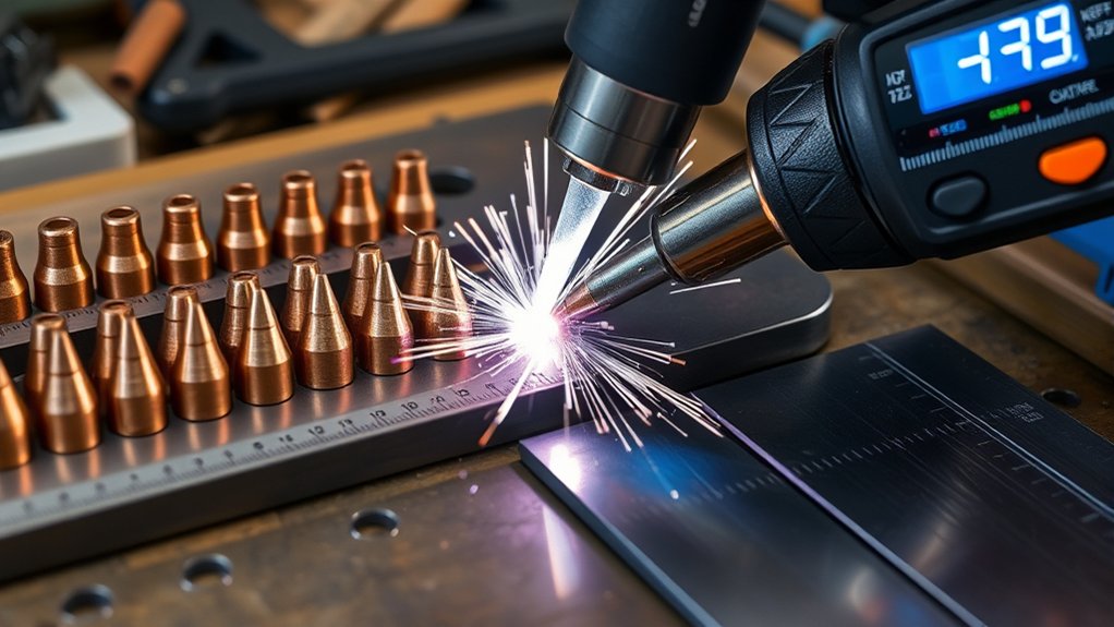
- Matching Tip Size to Material Thickness
- Amperage Ranges for Common Tip Orifice Sizes
- Cutting Speed Considerations by Tip and Metal
- Kerf Width and Tip Size Relationships
- Pierce Height and Standoff Best Practices
- Gas Pressure Settings by Tip and Amps
- Consumable Wear: When to Change Nozzle and Electrode
- Brand Cut Charts vs. Universal Guidelines
- Quick Reference: Tip Sizes From 20A to 80A
- Frequently Asked Questions
- Conclusion
Wrong plasma tip size can ruin a clean cut before you even start moving the torch. Choosing the right plasma tip starts with matching the nozzle orifice to material thickness, amperage, gas pressure, and the machine’s OEM cut charts. You’ll use the machine’s rated current first, then tune standoff and travel speed to control kerf, bevel, and dross.
Quick Answer
Choose a plasma tip by matching the tip’s amp rating to your machine setting and material thickness. Use the manufacturer’s cut chart as your main guide, then test on scrap before cutting the final part. A smaller tip helps with thin sheet and tighter kerf, while a larger tip supports more current and faster cutting on thicker material.
Key Takeaways
- Match the plasma tip to amperage first, then confirm thickness, pressure, and speed.
- Use OEM cut charts before universal settings because each torch and consumable set can behave differently.
- Set gas pressure under flow so the torch sees the pressure it uses during cutting.
- Measure kerf on scrap before you cut parts that need a tight fit or clean edge.
- Replace worn nozzles and electrodes together when cut quality starts to drift.
Matching Tip Size to Material Thickness
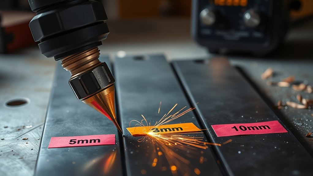
Start by matching tip amperage to material thickness and the settings listed for your torch. You’ll improve cut quality and consumable life when tip selection follows tested machine parameters.
For thin-gauge stock, a lower-amp tip often gives better control and a narrower heat-affected area. For thicker material, you need a larger orifice that can support higher current without overloading the nozzle.
Common light-duty ranges often place 20 A tips near thin sheet, 30 A tips near light plate, and 40 A to 50 A tips near thicker small-shop work. Treat these as starting points only, because torch design and consumable geometry change the final setting.
Confirm your torch’s rated pressure window and verify the orifice geometry against the OEM chart. If coatings, alloys, or surface condition vary, test a conservative amperage on scrap and document your qualified settings.
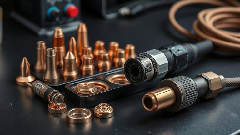
Products Worth Considering

10 pcs TIPS (Extended) /10 pcs ELECTRODE (Extended) /10 pcs SHIEDED-CUP/10 pcs GAS RING

Fit for : AG-60 AG-60P SG-55 WSD-60 Plasma cutter torch head

[Achieve Precise Cuts] PT31 Plasma Cutting Consumables – Your Essential Tool for Efficient Cutting! Whether you're working with sheet metal, steel, or any other material, superior cutting performance ensure clean, accurate, and smooth cuts.
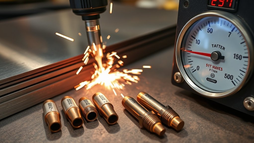
Amperage Ranges for Common Tip Orifice Sizes
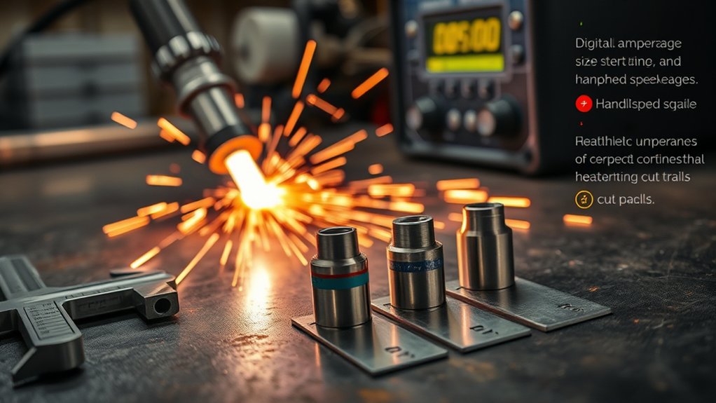
For each common orifice size, match the tip to a defined amperage band and a matching gas pressure range. The tip should carry the current without creating a loose arc, heavy dross, or fast nozzle wear.
Use this simple starting pattern when your manufacturer chart is not available:
- Use a 20 A tip for low-current thin sheet cutting.
- Use a 30 A tip when you need more speed on light material.
- Use a 40 A tip for moderate output and stronger arc control.
- Use a 50 A tip when the material needs more current and a wider kerf is acceptable.
- Use 70 A to 80 A tips only when your machine and torch support that output.
Do not run a small tip above its rated band. Overdriving the orifice can cause double-arcing, poor edge shape, and short consumable life.
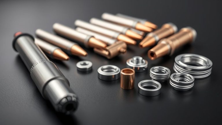
Products Worth Considering

Package list : Plasma torch S45 tips kit

SmartSYNC torches for the Powermax65/85/105 SYNC systems

SET INCLUDES-2-Plasma Cutting Tips, diameter: 0. 26 mm
Tip Size to Amps
Two factors define plasma tip selection: orifice size and the amperage you intend to run. Match the tip to the current window to maintain arc stability, cutting efficiency, and tip life.
Use lower-amp tips when you cut thin stock, fine details, or short shapes. Step up in tip size when the job needs more heat, faster travel, or full penetration through thicker material.
Staying within the rated amperage window limits double-arcing and keeps the kerf more predictable. It also helps you maintain edge quality across repeat cuts.
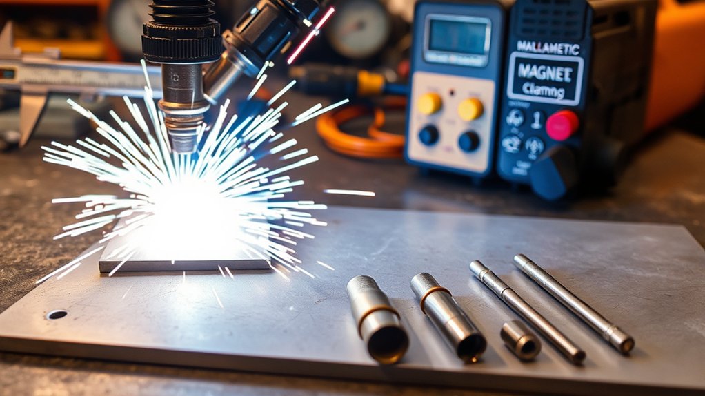
Pressure Ranges by Size
Although amperage and orifice size set the main process window, gas pressure helps stabilize the arc. It also controls jet velocity and protects consumables during the cut.
Smaller tips usually need lower pressure than larger tips, but the exact value depends on torch design. Set pressure while air flows through the torch, not while the system sits idle.
Verify inlet supply and make pressure adjustments under flow. Monitor cut face, dross, and kerf angle while you fine-tune the setting.
Prioritize tip maintenance. Keep orifices round, clean, and aligned, and replace eroded nozzles before they damage cut quality.
Note: Universal amp and pressure ranges help as starting points, but your OEM cut chart should decide the final settings.
Cutting Speed Considerations by Tip and Metal
A correct cutting speed depends on metal type, thickness, and the amperage-tip pairing. Start with charted inches per minute values when your machine manual provides them.
Higher amperage with a matching tip can let you move faster while keeping the cut clean. A larger tip supports thicker sections and higher travel rates, while a smaller tip favors thin sheet, tighter detail, and slower movement.
- Select amperage and tip size based on the material thickness and the machine chart.
- Set travel speed from the chart, then adjust after reading the cut edge.
- Validate the cut by metal type, since mild steel, stainless, and aluminum can react differently.
Heavy bottom dross often points to travel speed, torch height, amperage, or pressure problems. Change one setting at a time so you can see which adjustment improves the cut.
Kerf Width and Tip Size Relationships
You should tie nozzle size directly to kerf, material, amps, pressure, and travel speed. A larger orifice can carry more current, but it often leaves a wider cut path.
Do not assume the nozzle orifice equals the finished kerf. The actual kerf can run wider because the arc, gas flow, torch height, and travel speed all affect the cut.
Set gas pressure to the manufacturer’s specs to maintain a stable arc column. Too much or too little pressure can change kerf width, bevel, and dross.
Nozzle Size vs. Kerf
Two variables drive kerf in plasma cutting: nozzle orifice and current. You control kerf quality by matching orifice size to amperage, then confirming the result on scrap.
Larger orifices carry higher current, but they can widen the cut path. Smaller orifices can help with fine work, but they cannot handle more current than their rating allows.
- Select by thickness and choose the smallest rated orifice that can complete the cut.
- Correlate amps and kerf by measuring the test cut after settings stabilize.
- Verify cut data in your procedure sheet and record the actual kerf.
Material, Amps, Pressure
Three linked variables govern kerf and cut quality in plasma cutting: material, amperage, and gas pressure. Conductive metals, coatings, and surface scale can all change how the arc behaves.
Size the tip to the amperage and the material. Then set pressure and travel speed so the arc removes molten metal cleanly from the cut path.
Match amps to thickness first, then select the tip and pressure. Use disciplined tip maintenance and consistent cutting techniques to maintain dimensional accuracy.
Pierce Height and Standoff Best Practices
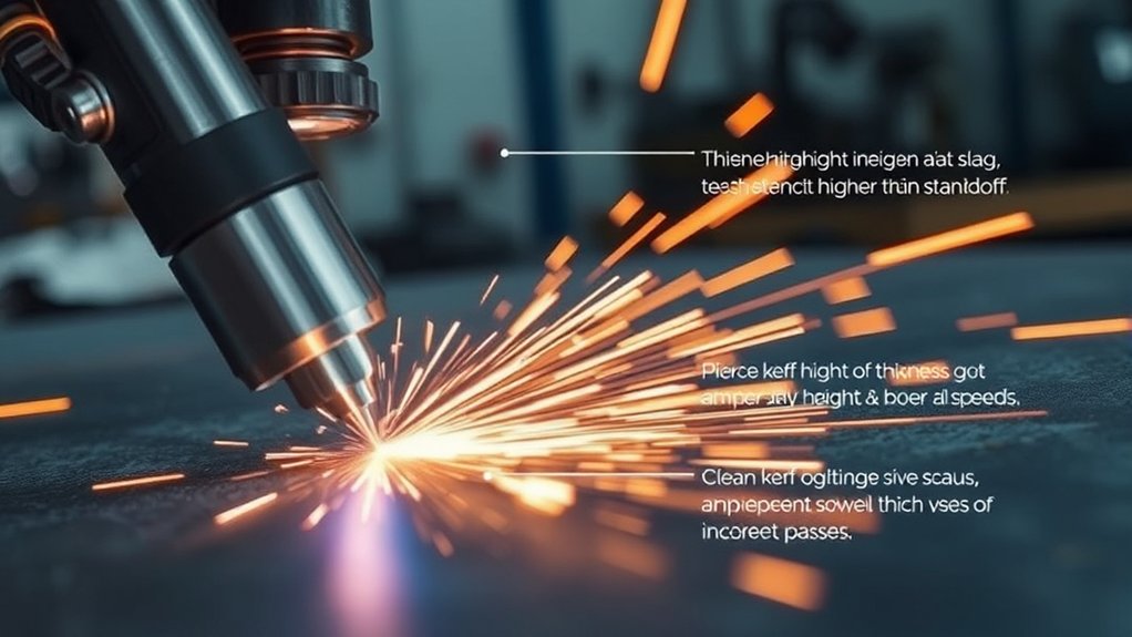
Precision starts at the arc. Set pierce height above the final cutting height so molten metal does not blow back into the nozzle during initiation.
Set pierce height above cut height, then hold a steady standoff to protect consumables and keep the cut clean.
You’ll control energy density and protect the nozzle by managing pierce height and standoff distance with care. Incorrect torch-to-work distance skews the plasma column, drives bevel, and increases rework.
Use a consistent routine:
- Verify torch height control zero before you start the cut.
- Program pierce height from the OEM chart, then wait until the arc penetrates.
- Move to the listed cut height before full travel speed begins.
- Audit cut coupons for edge angle, lag lines, top spatter, and bottom dross.
Correct setup extends consumable life, stabilizes arc voltage feedback, and reduces secondary grinding.
Warning: Piercing too low can force molten metal into the nozzle and damage consumables quickly.
Gas Pressure Settings by Tip and Amps
With torch height locked in, set gas pressure to match tip size and amperage. The jet needs enough pressure to maintain a stable, constricted arc and clear molten metal from the kerf.
Calibrate at the regulator with air flowing through the torch. Then verify that dynamic pressure stays within the range listed for your torch and consumables.
| Tip Class | Pressure Guidance | Best Use |
|---|---|---|
| Low amp | Use the lower OEM pressure range | Thin sheet and fine detail |
| Mid amp | Use the middle OEM pressure range | General shop cutting |
| High amp | Use the higher OEM pressure range | Thicker plate and faster travel |
If the arc wanders or bevel increases, adjust gas pressure in small steps while holding amperage constant. Make one change at a time, then check the cut face again.
Consumable Wear: When to Change Nozzle and Electrode
Discipline starts at the torch. Monitor consumable wear and change parts before cut quality drops.
You’ll hold tolerance only if you treat consumables as controlled items. Inspect the nozzle orifice, and replace it when you see ovality, keyholing, burnback, or heavy spatter adhesion.
Pair nozzle checks with electrode maintenance. Swapping the nozzle and electrode together helps prevent mismatched wear that creates taper, dross, and arc instability.
Adopt a data-driven cadence:
- Check visual wear: Replace electrodes when pitting grows, and replace nozzles when the orifice loses symmetry.
- Watch operating conditions: Inspect more often during thick-plate cuts, high duty cycles, poor air quality, or unstable torch height.
- Track usage: Log pierces, arc-on time, material type, and cut quality changes.
Change the nozzle and electrode at the same time when possible. Track results and adjust intervals based on cut quality, not guesswork.
Brand Cut Charts vs. Universal Guidelines
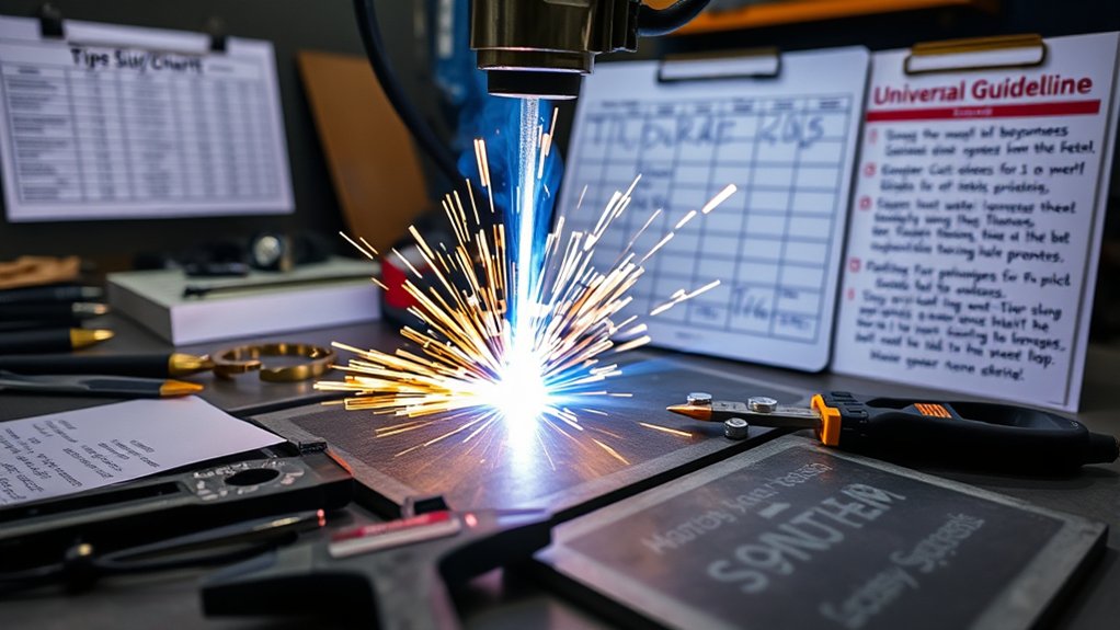
Consumable control sets the baseline, but settings lock in the result. Use brand cut charts first because manufacturers test amperage, arc voltage, pierce height, cut height, travel speed, and gas pressure by material and thickness.
Those datasets account for nozzle orifice geometry, swirl ring flow, and power-supply behavior. You’ll usually reach a clean setup faster with less trial and error.
Universal guidelines help when documentation is missing, but they generalize across machines with different flow curves and arc density. Expect variance in kerf, bevel angle, and dross.
Universal guidelines help when docs are missing, but machines vary, so expect kerf, bevel, and dross differences.
When results drift, return to the manufacturer’s chart to re-baseline amperage, speed, and pressure by tip size. Then validate by test coupons and record kerf width, surface finish, edge rounding, and dross level.
Quick Reference: Tip Sizes From 20A to 80A
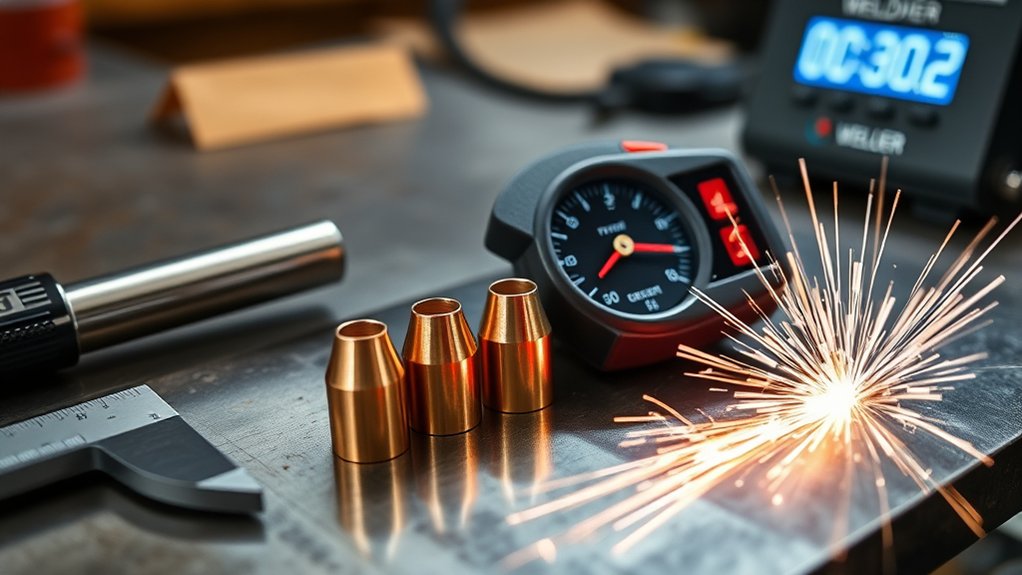
Common tip sizes cover most light industrial cutting, and each one pairs an orifice class with an amperage range. Use this quick reference to plan your setup before you check the OEM chart.
Use this guide to align tip selection with your target current and cut quality needs:
Low-Amp Tip Class
- 20A tip: Choose for thin-gauge material, tight kerf, and low heat input.
- 30A tip: Choose for light plate when you need more cut speed.
Mid-Amp Tip Class
- 40A tip: Choose for moderate thickness and stronger arc control.
- 50A tip: Choose when you need more throughput and can accept a wider kerf.
High-Amp Tip Class
- 70A tip: Choose for heavier work when the machine supports that output.
- 80A tip: Choose for higher output cutting with the correct torch and consumables.
Match the amperage setpoint to the tip’s rated band. Don’t overdrive small orifices, and verify supply pressure at the torch under flow.
Pro tip: Keep a small notebook of tip size, material, pressure, speed, and kerf for repeat jobs.
Frequently Asked Questions
How Do Tip Materials Affect Cut Quality?
Tip material can affect heat transfer, wear, and orifice life. You should choose the material and design recommended for your torch rather than mixing parts by appearance.
Do Humidity or Shop Temperature Impact Plasma Tip Performance?
Yes. Moisture in the air supply can cause arc instability, fast nozzle wear, and poor cut quality. Use clean, dry air and follow the dryer or filter guidance for your plasma cutter.
What Tip Maintenance Routines Extend Nozzle and Electrode Life?
You extend nozzle and electrode life by checking orifices before use, keeping air dry, and holding correct standoff. You should also track pierces and replace parts before poor cuts become routine.
How Does Air Quality or Filtration Influence Tip Choice?
Air quality affects all tip sizes, but small orifices can show problems sooner. If your shop air contains moisture or oil, improve filtration before you blame the tip size.
Are Different Tips Needed for CNC Versus Hand-Held Torches?
Yes, CNC and hand-held torches can use different consumables, shields, and height-control requirements. Use amperage-matched, torch-compatible parts from the manufacturer’s chart.
Conclusion
The best plasma tip is the one that matches your amperage, material thickness, pressure range, and torch design. Start with the OEM cut chart, then test on scrap before making final cuts.
Watch the kerf, bevel, dross, and consumable wear after every setting change. Keep a record of the settings that work so you can repeat clean cuts with less waste.
When cut quality slips, return to the basics: correct tip size, dry air, steady standoff, and fresh consumables.