
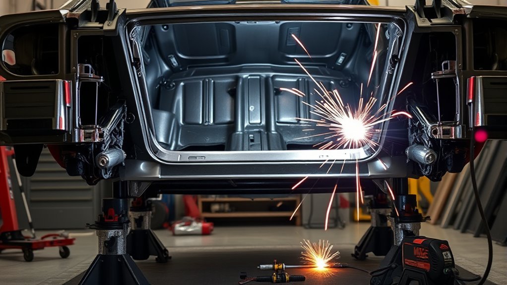
A unibody shell can twist, sag, or lock in the wrong position if structural bracing is welded in without the correct support and measurements. Strong-looking welds do not guarantee a safe result. To add weld-in bracing to a unibody car, first confirm that the vehicle, material, and bracing design can be welded, then support the shell in the specified load condition, protect every nearby system, fit the parts without forcing them, and follow the approved weld and corrosion-protection procedure.
Quick Answer
Support the unibody exactly as the vehicle or bracing-kit instructions require, record body dimensions and door gaps, and identify the metal before welding. Fit an engineered brace to approved load points, use the specified weld type and sequence, control heat, inspect every joint, restore corrosion protection, and verify alignment and vehicle systems before driving.
Key Takeaways
- Use the vehicle-specific body repair information and the bracing manufacturer’s instructions before cutting, drilling, or welding.
- Do not assume every unibody is mild steel or that ordinary MIG stitch welds are acceptable.
- Support and measure the shell before work begins, then recheck the same datum points after tacking and welding.
- Remove or protect fuel, brake, electrical, interior, underbody, SRS, and high-voltage hazards on both sides of the weld area.
- Restore primer, seam sealer, undercoating, and internal cavity protection after the welds pass inspection.
At a Glance
| Time Required | A full day or longer for a pre-engineered connector kit; several days for custom fitting, structural preparation, coating, curing, and alignment checks |
| Difficulty | Advanced structural fabrication; professional help is recommended for late-model, damaged, rusted, aluminum, bonded, UHSS, hybrid, or electric vehicles |
| Tools Needed | Vehicle body dimensions, kit instructions, approved welder and consumables, frame bench or rated support equipment, tram gauge, clamps, grinder, fume extraction, PPE, heat shields, and fire extinguisher |
| Cost | Varies widely by vehicle, kit, rust repair, access, coating system, alignment work, diagnostic requirements, and professional labor; obtain a vehicle-specific written quote |
What’s in This Article
- Decide Whether the Unibody Can Be Safely Braced
- What Weld-In Bracing Does for a Unibody
- Pick the Best Bracing Points
- Support and Square the Shell
- What You’ll Need Before Welding
- Fit Subframe Connectors and Crossmembers
- Prepare the Metal and Welding Setup
- Weld Without Warping the Body
- Inspect the Welds Before Coating
- Common Mistakes That Can Weaken the Bracing
- Seal, Paint, and Recheck Alignment
- Final Checks Before Driving
- Sources
- Frequently Asked Questions
- Conclusion
Decide Whether the Unibody Can Be Safely Braced
Before choosing tubing or turning on a welder, confirm that the project has a safe, documented path. A pre-engineered subframe-connector kit for an older mild-steel car is different from welding a custom crossmember into a late-model passenger cell.
Obtain the vehicle-specific body repair manual or workshop information, the body-dimension chart, and the complete bracing-kit instructions. Identify the proposed attachment points, steel grade, panel layers, factory adhesives, corrosion coatings, wiring routes, fuel components, restraint-system parts, and high-voltage equipment.
Modern body structures may include mild steel, high-strength steel, ultra-high-strength steel, aluminum, castings, rivets, structural adhesive, and factory spot welds in the same area. Honda’s published body repair information explains that welding procedures vary with the tensile strength of the metal. Never assume a generic wire, gas, joint, or bead pattern is acceptable.
Inspect for Rust, Damage, and Previous Repairs
Do not use bracing to hide a weak shell. Inspect the rockers, floor, torque boxes, suspension mounts, frame rails, pillars, pinch flanges, and proposed weld zones for:
- Perforation or deep scaling
- Cracks around suspension or drivetrain mounts
- Torn spot welds or separated panel seams
- Collision buckling or shifted datum points
- Old patches, excessive filler, or unknown welds
- Heat damage, fire damage, or badly thinned metal
If structural rust or collision damage is present, repair and measure the original structure before adding reinforcement. A brace welded across damaged metal may transfer load into another weak area instead of solving the problem.
Know When Not to Weld
Stop and use a qualified structural fabricator or collision-repair technician when the proposed attachment point is not covered by an engineered kit or verified design, when the material cannot be positively identified, or when the vehicle maker restricts welding or sectioning in that area.
Ford’s current structural repair position statement emphasizes following published vehicle procedures because body components work together as part of the vehicle’s structural and occupant-protection system.
Warning: Adding untested reinforcement can change how crash forces travel through the body. A stiffer shell is not automatically a safer shell. Do not weld across crush zones, seat-belt mounts, airbag sensor areas, battery enclosures, or occupant-cell components without an approved design and vehicle-specific procedure.
Power Down Electrical, SRS, and High-Voltage Systems
Follow the vehicle maker’s exact power-down procedure before welding. Switching off the ignition is not enough, and disconnecting only the negative 12-volt terminal may not isolate every circuit on every vehicle.
- Record radio, window, steering-angle, and other relearn requirements before disconnecting power.
- Follow the specified SRS and pretensioner waiting period.
- Keep welding current away from modules, wiring, bearings, sensors, and restraint-system grounds.
- Do not cut, clamp, drill, heat, or weld near orange high-voltage cables or labeled high-voltage components.
- Have a properly trained technician isolate and verify a hybrid or EV high-voltage system.
NHTSA high-voltage safety guidance warns against contact with orange high-voltage cabling. Honda also directs technicians to isolate high voltage before welding or electrical repairs on applicable hybrid vehicles.
What Weld-In Bracing Does for a Unibody
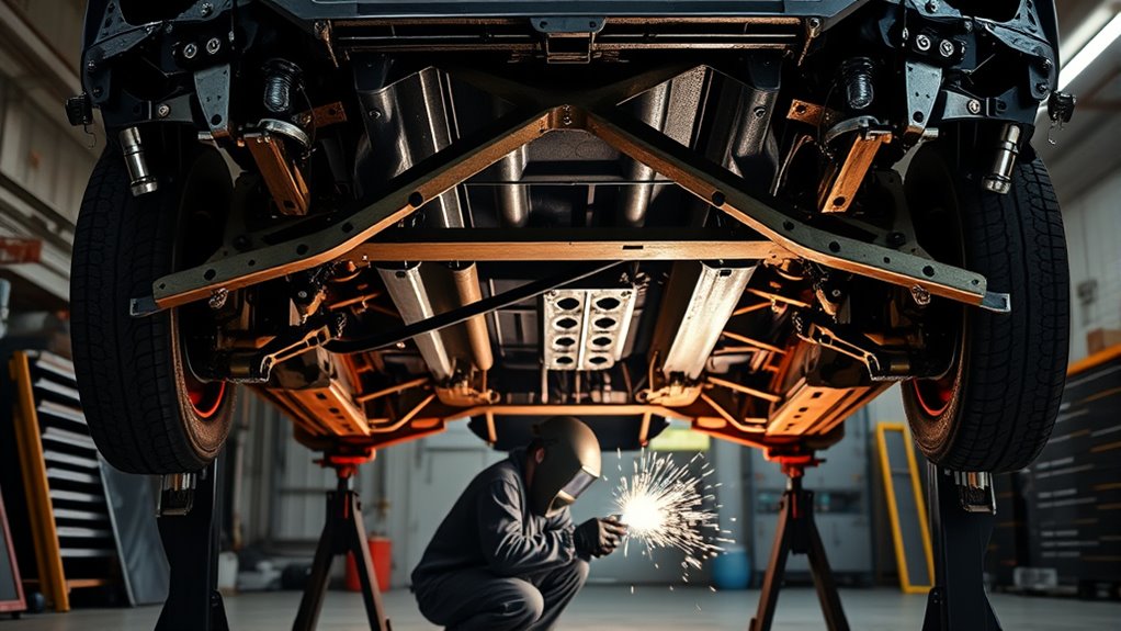
Properly engineered weld-in bracing can increase a unibody car’s torsional and bending stiffness. Reducing shell deflection can make suspension response more consistent during braking, cornering, and acceleration.
Subframe connectors, rocker reinforcement, torque-box reinforcement, and crossmembers work by linking existing structural load paths. They should spread force into sound, adequately sized metal instead of concentrating it at one short weld or thin floor section.
Bracing may reduce temporary movement around door openings, floors, and suspension mounts during hard use. It will not repair worn door hinges, a cracked pillar, structural rust, or collision misalignment.
Extra stiffness can be useful on competition vehicles, high-power builds, convertibles, and older shells fitted with modern tires or suspension. It can also add weight, increase noise or vibration, reduce ground clearance, block service access, and alter crash-energy management.
Note: Weld-in bracing is a structural modification, not a substitute for collision repair. Confirm insurance, warranty, inspection, registration, class, and motorsport-rule requirements before modifying a road vehicle.
Pick the Best Bracing Points
Start with the engineered design, not with whichever sheet metal is easiest to reach. Effective bracing normally links established structural areas such as factory rails, torque boxes, rockers, crossmembers, suspension-load paths, or reinforced floor junctions.
Subframe connectors are commonly used to link stronger front and rear underbody sections. The connector and its attachment plates must fit the vehicle closely and distribute load across enough sound metal.
A brace is only as effective as the structure it connects. Tie into verified load paths, not isolated sections of thin floor sheet.
Check the full route for brake lines, fuel lines, vapor lines, wiring harnesses, drains, exhaust heat, driveline movement, seat mounts, jacking points, suspension travel, and service access. Relocate a component only through an approved method that preserves its support, clearance, abrasion protection, and function.
Do not weld over factory seam sealer, undercoating, paint, rust, adhesive, or zinc-rich coating without following the approved preparation process. Remove coatings only far enough to create the required clean weld area, and plan how every exposed surface will be protected afterward.
Choose an Engineered Bracing Design
A vehicle-specific kit is normally safer than an improvised brace because its shape, attachment plates, clearances, and welding instructions have been developed for that platform. Confirm that the kit matches the exact body style, wheelbase, transmission, exhaust layout, convertible or hardtop configuration, and model year.
For custom work, tube size, wall thickness, material grade, bend radius, joint shape, attachment area, and weld length must be selected as a system. Boxed tube, round tube, channel, angle, and formed plate each behave differently. Shape alone does not prove that a part is strong enough.
Support and Square the Shell
Support the vehicle in the exact condition required by the bracing instructions or body manual. Some kits call for the chassis to sit at simulated ride height. Other procedures specify a frame bench, dedicated fixtures, particular lift points, or unloaded suspension.
Do not force a straight-looking shell into position with a brace. First establish whether the vehicle is already within the manufacturer’s dimensional tolerances.
Brace Door Openings
Temporary door-opening bracing may be needed when structural sections will be cut, when the roof or rocker has limited support, or when the body style is especially flexible. It may not be necessary for every connector installation, so follow the project design.
Use properly sized steel tubing or angle, not timber. Place the temporary braces where they hold the opening without obstructing the permanent joints. A diagonal member helps control racking, while an additional horizontal member may help preserve width.
- Record door gaps and opening dimensions before removing doors, glass, hinges, latches, or structural panels.
- Fit steel temporary braces to sound attachment areas.
- Tack or bolt the temporary structure as the approved process allows.
- Recheck the original dimensions before cutting or final tightening.
Level and Support the Shell Correctly
Set the unibody on a frame bench, lift, fixtures, stands, or simulated suspension supports rated for the vehicle. Do not place supports on thin floor sheet, damaged pinch flanges, fuel tanks, battery enclosures, or unsupported suspension parts.
A workshop floor does not need to be perfectly level if the measurement system establishes a repeatable datum plane. What matters is that the body is stable and that all measurements are compared with the same reference system.
Confirm that doors, hatch, hood, glass openings, rocker lines, and suspension mounting points are not being held under artificial twist. Correct the support condition before fitting the brace.
Lock In Datum Points
Use the manufacturer’s body dimensions when available. Record the centerline, datum heights, cross-body widths, suspension points, connector attachment points, and diagonal measurements.
A tram gauge, body-measuring system, laser, plumb bobs, straightedges, and tape measures may all help, but each reading must be taken from a repeatable point. Mark the locations and record the values instead of relying on memory.
- Measure and record the shell before disassembly.
- Confirm the required support condition.
- Recheck after temporary bracing.
- Recheck after fitting and tacking.
- Recheck after each major weld sequence and after full cooling.
What You’ll Need Before Welding
Plan the entire job before striking an arc. The actual equipment and consumables must match the kit, metal, body manual, and welder manufacturer’s instructions.
- Vehicle-specific body dimensions and repair information
- Complete bracing-kit instructions or an engineered fabrication drawing
- Frame bench, lift, fixtures, or heavy stands rated for the vehicle
- Steel temporary bracing where required
- Approved GMAW, MAG, MIG-brazing, resistance-spot, TIG, or other specified welding equipment
- Specified wire or filler, shielding gas, contact tips, and machine settings
- Matching scrap coupons for setup and destructive testing
- Grinder, abrasives, drill, hole saws, clamps, magnets, and deburring tools as permitted
- Tram gauge, measuring system, laser, plumb bobs, tape measure, and marker
- Welding helmet with the correct shade, safety glasses, welding gloves, flame-resistant clothing, and hearing protection
- Local fume extraction, ventilation, and respiratory protection selected for the coating and process
- Fire-resistant blankets, heat shields, an appropriate fire extinguisher, and a fire-watch plan
- OEM-specified primer, seam sealer, undercoating, topcoat, and cavity wax
- Scan tool, alignment equipment, and electrical test equipment where required
Pro Tip: Photograph and label every line, harness, shield, plug, bracket, clip, and coating before disassembly. The photos make it easier to restore routing, separation, fasteners, heat protection, and corrosion control correctly.
Products Worth Considering

Sateen Fabric: The IRONCAT 7050 FR Sateen cotton jacket features 9 oz. sateen fabric with black anodized snaps on the front for secure fastening
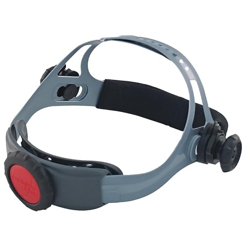
REPLACEMENT WELDING HELMET HEADGEAR - Jackson Safety's Premium 370 Speed Dial Replacement Headgear offers a perfect fit and secure hold for your welding hood

Fit Subframe Connectors and Crossmembers
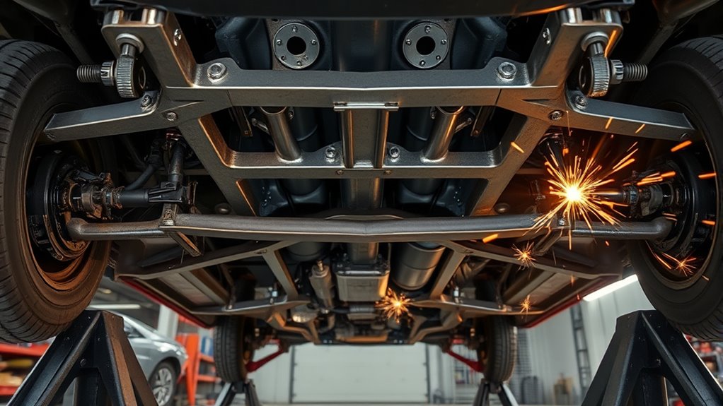
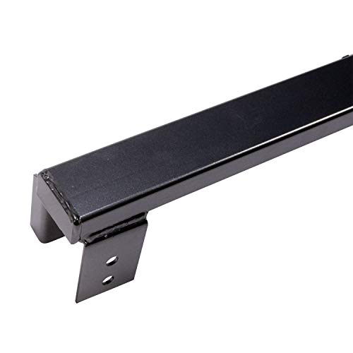
Trial-fit each connector or crossmember before removing more coating than necessary. A structural brace should sit against its intended attachment areas without using bolts, clamps, or welding heat to drag the shell or brace into shape.
Inspect the full length for exhaust, driveline, fuel, brake, vapor, wiring, battery, suspension, and ground-clearance conflicts. Check movement through the suspension’s operating range where applicable.
Tack the part only after the shell measurements and clearances are correct. Use enough tacks to prevent movement, but leave room to correct fit before the final weld sequence.
Products Worth Considering

Welding Cable Quick Connector Male & Female Pair With Accessories.
BBK is your Number One Aftermarket Performance Brand in the USA - American Designed and Built

BBK is your Number One Aftermarket Performance Brand in the USA - American Designed and Built
Subframe Connector Fitment
Fit the left and right connectors as a pair. Compare their fore-and-aft position, height, angle, attachment overlap, and clearances before welding either side completely.
- Confirm the vehicle is supported as instructed.
- Mark the connector position and all coating-removal limits.
- Trim or grind the connector, not the vehicle structure, unless the instructions specifically require body modification.
- Deburr every cut and remove sharp edges.
- Confirm the specified fit-up and joint gap.
- Clamp the connector without deforming the floor or rocker.
- Tack both sides and remeasure the shell.
If a brake, fuel, vapor, or electrical line crosses the work area, remove or relocate it only through the proper service procedure. Do not bend a line sharply, trap it between the brace and body, or leave it close enough to chafe or absorb welding heat.
Crossmember Placement Options
Place a crossmember only where the design connects meaningful load paths and provides enough attachment area. Common locations may be near reinforced floor junctions, torque boxes, rails, transmission supports, or suspension structures, but the correct position is vehicle-specific.
Maintain service access to the transmission, driveshaft, exhaust, fuel tank, battery, parking-brake cables, and suspension hardware. Check whether the part changes jacking access or creates a low point that can strike the road.
Do not attach a heavy crossmember to a broad area of unsupported floor sheet without load-spreading plates or another engineered connection. A stiff tube can tear away from a thin panel when its loads are concentrated into a few short welds.
Prepare the Metal and Welding Setup
Remove Coatings and Control Fumes
Expose clean metal only within the area required for the specified weld. Remove paint, seam sealer, undercoating, rust, adhesive, oil, and incompatible coatings from both sides where access allows.
Automotive steel may have zinc or other protective coatings. Heating galvanized surfaces can release zinc-oxide fumes. The NIOSH Pocket Guide for zinc oxide lists metal fume fever, cough, chest tightness, and breathing difficulty among possible exposure effects.
Use local fume extraction close to the arc, provide clean replacement air, and wear respiratory protection when the hazard assessment and product instructions require it. Do not rely on an open garage door alone when fumes can collect beneath or inside the vehicle.
Clear the Hot-Work Zone
Inspect both sides of every proposed weld. Sparks and heat can pass through seams or conduct into hidden areas.
- Remove carpet, insulation, foam, trim, sound deadener, and loose undercoating from the heat zone.
- Move or shield fuel, brake, vapor, hydraulic, refrigerant, and electrical components.
- Check enclosed rockers, rails, pillars, and floor cavities for foam or debris.
- Keep an appropriate extinguisher immediately available.
- Assign a second person to watch the opposite side when visibility is limited.
OSHA’s welding and hot-work requirements address combustible removal, guarding, ventilation, and fire watches. When conditions require a fire watch, maintain it for at least 30 minutes after welding and longer if heat remains or smoldering is possible.
Warning: Never weld on or near a fuel tank, fuel vapor component, pressurized line, refrigerant circuit, battery enclosure, pyrotechnic restraint device, or high-voltage component until the applicable system has been made safe through the manufacturer’s service procedure.
Verify the Welder on Test Coupons
Prepare coupons that match the base-metal type, thickness, coating condition, overlap, plug-hole size, and joint design as closely as possible. Set the machine using the equipment and repair instructions, then produce sample welds.
Inspect the samples for fusion, penetration, porosity, burn-through, cracking, excessive heat, and easy separation. Bend, peel, or otherwise destructively test the coupons as the applicable procedure requires. Do not use the vehicle as the first test piece.
Confirm wire or filler classification, shielding gas, polarity, voltage, wire speed, pulse program, tip condition, gun angle, and travel speed. Late-model structural steel may require a specific wire or attachment method rather than ordinary ER70S-6 solid wire.
Place the Welding Return Clamp Correctly
Attach the welding return clamp to clean metal as close as practical to the weld area while following the vehicle and welder instructions. The intended current path should not pass through wheel bearings, hinges, electronic modules, wiring grounds, fuel-system parts, or other sensitive assemblies.
Weld Without Warping the Body
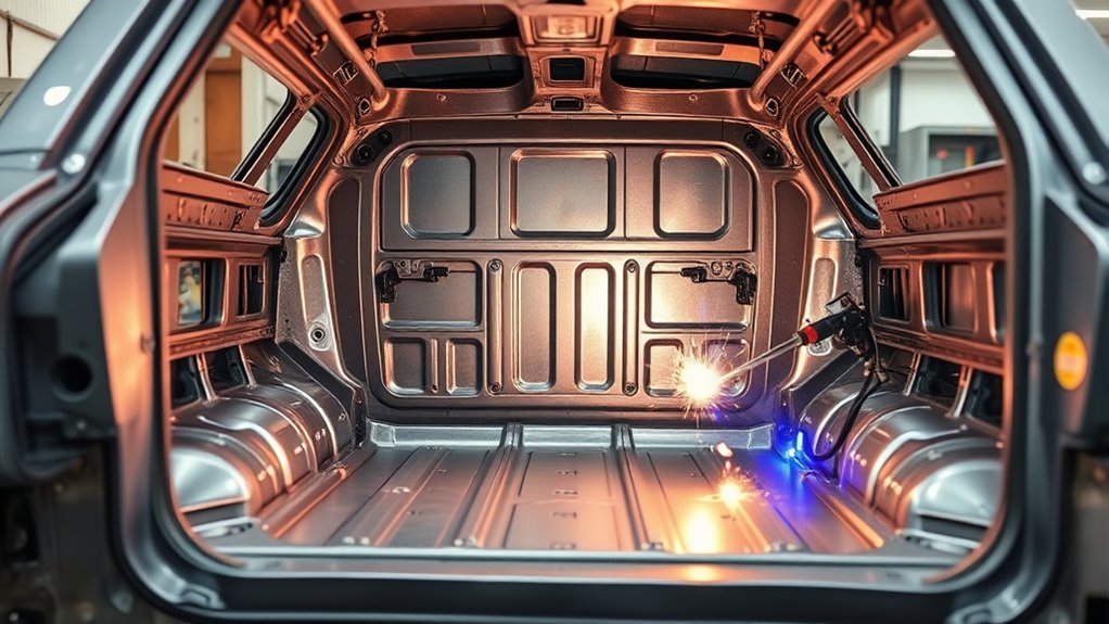
Heat control matters, but the approved joint design comes first. Follow the specified weld type, location, hole diameter, length, spacing, sequence, wire, gas, and equipment settings.
The vehicle-specific procedure or engineered kit—not a generic bead pattern—determines how structural bracing should be attached.
- Confirm all measurements, clearances, power-down steps, shielding, and fire controls.
- Tack both sides of the vehicle before completing one side.
- Recheck the recorded datum points and door gaps.
- Apply the specified welds in a balanced sequence.
- Where short alternating welds are permitted, move between separated locations and allow cooling pauses.
- Do not quench hot structural steel unless the procedure specifically allows it.
- Stop if the joint opens, the shell measurement changes, the panel oil-cans, coating catches fire, or the weld quality changes.
- Allow the structure to cool naturally before the final measurement.
Do not grind a structural weld flush merely for appearance unless the procedure permits it. Excessive grinding can reduce the weld throat, thin the attachment plate, and hide undercut or poor fusion.
Inspect the Welds Before Coating
Clean the weld area enough to inspect it without removing sound weld metal. Use the acceptance criteria supplied by the kit maker, OEM procedure, welding standard, or project engineer.
Look for:
- Cracks in the weld or heat-affected zone
- Porosity or pinholes
- Undercut along the weld toe
- Incomplete fusion
- Missed plug welds or insufficient plug fill
- Burn-through and thin surrounding metal
- Sharp starts, stops, or craters
- Distortion, opened seams, or changed body dimensions
- Damage to adjacent lines, wiring, coatings, or components
Repair defects with an approved method. Repeatedly welding over a defective joint can add excessive heat without correcting contamination, poor access, incorrect settings, or bad fit-up.
Common Mistakes That Can Weaken the Bracing
- Welding before confirming the vehicle is structurally straight
- Using an attachment point that is not part of a verified load path
- Failing to identify high-strength steel, aluminum, adhesive, or layered construction
- Using timber or other combustible temporary bracing
- Supporting the shell in an arbitrary position instead of the specified load condition
- Forcing a brace into place and locking stress into the body
- Welding over paint, rust, zinc, sealer, adhesive, or undercoating
- Using ordinary wire, gas, plug-hole size, or bead spacing without verification
- Completing one side before tacking and measuring the other
- Running long welds where the design calls for separated attachments
- Passing welding current through bearings, modules, or wiring grounds
- Failing to inspect the opposite side for fire or heat damage
- Grinding welds until the effective joint is too small
- Applying seam sealer over contamination or unprotected bare metal
- Leaving enclosed welded sections without cavity protection
- Driving before checking alignment, lines, wiring, exhaust, diagnostics, and suspension clearance
Note: A brace that fits only when heavily clamped, heated, or pulled into position is warning you that the design, support condition, part, or shell dimensions are wrong. Stop and correct the cause before adding more weld.
Seal, Paint, and Recheck Alignment
Once the welds pass inspection and the metal has cooled, restore corrosion protection in the correct order. Product compatibility and the vehicle maker’s procedure control the exact system.
- Remove weld residue, loose coating, and contamination without thinning the joint.
- Apply the specified epoxy, direct-to-metal, or other approved primer to exposed surfaces.
- Apply seam sealer over the substrate required by the product and OEM procedure.
- Restore chip coating, undercoating, paint, and heat protection where applicable.
- Apply cavity wax or another approved rust-preventive treatment inside welded rockers, rails, overlaps, and inaccessible backsides.
- Keep coatings off exhaust parts, drains, threads, electrical grounds, sensors, and moving components.
Honda’s corrosion-protection guidance specifies seam sealer over an appropriate cured primer rather than directly over bare metal and calls for cavity treatment inside welded panels.
Weld-through primer is not a universal final coating. Use it only where the applicable repair or product procedure permits it, and remove residue that would interfere with weld quality or later coatings.
Allow every primer, sealer, coating, and cavity product to flash and cure for the manufacturer’s stated time. Recheck drains and ventilation openings so coatings do not trap water inside the reinforced structure.
Final Checks Before Driving
Do not remove temporary braces until the permanent structure is complete, fully cooled, and within the recorded dimensions. Remove the temporary braces in a balanced sequence and measure again.
Complete the following checks before the vehicle returns to service:
- Confirm door, hood, hatch, roof, glass, and panel gaps.
- Measure the original datum points and diagonals.
- Inspect brake, fuel, vapor, refrigerant, hydraulic, and electrical routing.
- Check wiring clips, grounds, grommets, shields, and heat protection.
- Confirm exhaust, driveshaft, transmission, suspension, steering, tire, and parking-brake clearance.
- Check that drains, jacking points, and service access remain usable.
- Restore the SRS, 12-volt, and high-voltage systems through the approved procedure.
- Perform pre- and post-repair diagnostic scans where required.
- Complete any steering-angle, window, battery, seat, camera, radar, or other relearns.
- Inspect for fuel, brake-fluid, coolant, refrigerant, or exhaust leaks.
- Check wheel alignment and thrust angle when the work could affect suspension or body geometry.
- Perform a cautious road test only after the vehicle passes all static checks.
Reinspect the brace and surrounding metal after the initial driving period specified by the kit maker or fabricator. Look for cracked coating, fretting, contact marks, loose nearby hardware, new noises, or changes in alignment.
Sources
- OSHA 29 CFR 1910.252—Welding, Cutting, and Brazing — fire prevention, ventilation, guarding, PPE, and fire-watch requirements
- NIOSH Pocket Guide to Chemical Hazards—Zinc Oxide — zinc-oxide fume exposure symptoms and controls
- Honda 2023 Integra Body Repair Information — high-strength and ultra-high-strength steel identification and procedure-dependent welding
- Honda Corrosion Protection for Vehicle Repair — primer, seam sealer, undercoating, backside treatment, and cavity wax
- Ford Motor Company Structural Repairs Position Statement — OEM procedures, crash performance, material compatibility, and structural safety
- NHTSA Electric and Hybrid-Electric Vehicle Safety Guidance — orange high-voltage cable and component precautions
Frequently Asked Questions
How do you strengthen a unibody car?
A unibody can be strengthened with an engineered combination of subframe connectors, rocker or torque-box reinforcement, crossmembers, seam reinforcement, strut or suspension bracing, and an approved roll structure. The right method depends on the vehicle, material, intended use, and existing load paths. Structural rust or collision damage must be repaired first.
Do unibody cars have pinch welds?
Yes. Unibody vehicles commonly use pinched and welded panel flanges along rockers, floors, pillars, wheelhouses, and other body joints. A visible rocker pinch flange may also serve as a jacking location, but that does not mean it is automatically an approved place to attach a structural brace.
How much does car frame or unibody welding cost?
There is no reliable universal price. Cost depends on the vehicle, bracing kit, rust or collision repair, disassembly, access, materials, welding process, coating restoration, diagnostic scans, alignment, and labor rate. Obtain a written quote that lists preparation, welding, corrosion protection, reassembly, and final checks.
Can you repair an unibody frame?
Many damaged unibody components can be repaired or replaced by a qualified collision technician, but only where the vehicle maker provides an approved straightening, replacement, sectioning, welding, bonding, or riveting procedure. Some high-strength components must be replaced as complete parts and must not be heated or straightened.
Should you weld bracing with the suspension loaded?
Only when the bracing instructions specify a ride-height or simulated-load condition. Other procedures may require particular lift points, frame-bench fixtures, or unloaded suspension. Use the exact support method provided for the vehicle and kit rather than assuming one condition is correct for every unibody.
Can weld-in bracing make a car unsafe?
Yes. Poorly designed bracing can create concentrated loads, weak heat-affected zones, trapped corrosion, reduced ground clearance, interference with safety systems, or altered crash-energy paths. It may also lock a crooked shell in place. Use an engineered design and vehicle-specific procedures.
Can you weld modern high-strength unibody steel?
Sometimes, but not with a universal method. The permitted joint, heat input, wire, gas, equipment, sectioning location, and weld type depend on the steel grade and vehicle procedure. Some ultra-high-strength or hot-stamped components cannot be sectioned or conventionally welded except at specified factory joints.
Do you need to disconnect the battery before welding on a car?
Follow the vehicle maker’s welding power-down procedure. It commonly includes switching off the vehicle and disconnecting the 12-volt battery, but some vehicles require additional module, SRS, capacitor, hybrid, or high-voltage steps. A negative-terminal disconnect alone is not a complete procedure for every vehicle.
Conclusion
Good weld-in bracing starts with engineering, material identification, and alignment control—not with the first weld. Confirm that the proposed attachment is allowed, support the shell in the specified condition, record the body dimensions, clear every heat and electrical hazard, and fit the brace without forcing it.
Use the required welding process and verify it on matching coupons before touching the vehicle. After welding, inspect every joint, restore corrosion protection inside and outside the structure, recheck alignment, scan the vehicle where required, and confirm that brake, fuel, electrical, exhaust, driveline, suspension, SRS, and high-voltage systems are safe before driving.




