To measure weld bead width for quality control, you should use calibrated calipers, fillet weld gauges, or optical systems and measure at several points along the bead, with the midpoint as the main reference. Keep the tool or sensor perpendicular to the surface to avoid distortion, and compare results with the welding procedure specification. For image-based methods, apply fixed thresholding and validate against 3D scan data. Careful setup also helps reveal the errors that can affect results.
How to Measure Weld Bead Width
To measure weld bead width accurately, you can use a structured light vision system that projects a known pattern onto the bead and extracts its geometric profile even under intense arc radiation. You then capture the scene with high-speed cameras, often with 50 μs exposure, so image processing can resolve the bead within milliseconds. In laser welding, this approach gives you direct, noncontact measurement techniques that support quality control without slowing the process. You can improve image quality with Gaussian filters, then apply fixed thresholding to form binary images that isolate the weld bead width from the background. These vision systems work best when you keep the optics stable and the calibration consistent. For statistical validation, compare the vision result with 3D scanner data using Welch’s t-test. If the difference is insignificant, you’ve confirmed reliable performance. This frees you from guesswork and gives you measurable control over weld quality, ensuring compliance with maximum fillet weld size principles to maintain structural integrity.
Tools for Measuring Weld Bead Width
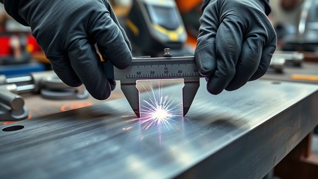
You can measure weld bead width with several tools, depending on the required accuracy and inspection method. For fast checks, you can use calipers or visual inspection tools to assess bead width while measuring the weld and spotting defects early. Fillet weld gauges give you direct, repeatable readings that support weld quality and confirm joint reinforcement against specification. When you need higher precision, digital measuring devices, including laser distance meters, provide non-contact data and work well on irregular shapes. Optical measuring systems use structured light or cameras to capture the bead profile and automate width analysis, which improves traceability and reduces operator bias.
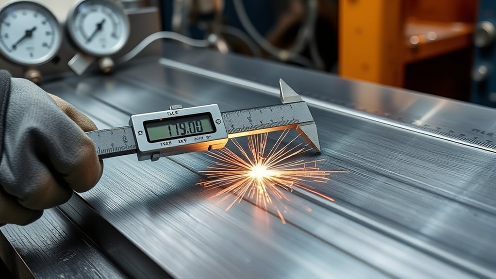
- Calipers: quick, precise millimeter readings.
- Fillet weld gauges: accurate standard compliance checks.
- Optical and digital systems: high-accuracy, automated measurement.
You should select the tool that matches your inspection tolerance and production workflow. In adaptive control environments, measured width can feed process adjustments and strengthen weld quality without reducing your freedom to verify results independently. Additionally, using tools like auto darkening goggles can enhance your overall welding experience by ensuring effective eye protection while you measure.
Products Worth Considering

【High Accuracy】This laser measuring tool features long range measuring with extreme accuracy and measures distances up to 395 feet. Delivers up to ±1/16-inch accuracy, more precise than most laser tape measures. Laser class: Class 2, 490–560nm, <1mW
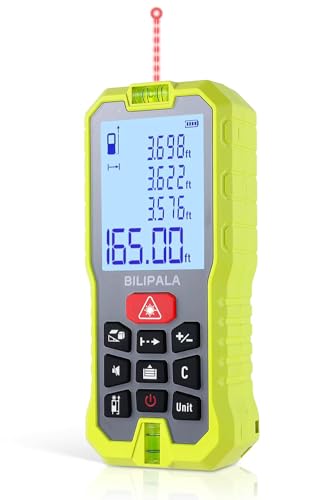
Built-in Dual Bubble Levels & Backlit LCD: 229ft/70M laser distance measure accuracy +/-1/16 inch (+/-2mm), with an inclination accuracy of up to ±0.3°.This Laser Measure features built-in high-sensitivity dual bubble levels for quick horizontal and vertical calibration, reducing measurement errors caused by handheld tilting. The 2-inch backlit LCD display ensures clear readings even in dim corners or bright outdoor conditions, making your work easier and more accurate
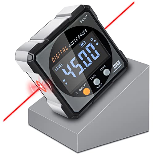
Nivel Digital Level with Laser - (Class II laser, Output<5mW) L2.4in, W2.4in, H1.2in, portable pocket size with matching belt bag. ±0.2° precise microprocessor with automatic inversion when upside down. 4*90° measurement can be used at many angles and can be zeroed at any angle for comparison.
Where to Measure Along the Weld Bead
Where along the bead should you take measurements? You should measure at multiple points along the weld bead surface to map weld bead geometry and detect variation. Use the midpoint as your primary reference point, then measure both ends to capture the full width profile. Place your calibrated measuring tool, such as a fillet weld gauge, perpendicular to the bead; angled contact can distort readings. Consistent orientation matters because welding parameters can shift local width and mask defects. Record each value for quality control and compare it against the Welding Procedure Specification to verify compliance. When you document the results, note location, orientation, and any surface irregularities. This approach gives you precise data, supports accountable inspection, and helps you identify nonuniformity before it becomes failure. By measuring systematically, you keep the evaluation transparent and technically sound. Additionally, ensure that you are aware of the potential for metal fume fever when working with certain materials, such as galvanized steel.
Weld Bead Width Standards
- Check welding procedure specifications first; they state target width ranges tied to service demands.
- Control process variables such as travel speed, current, and voltage, because small changes shift bead width quickly.
- Apply measurement techniques like laser sensors or high-speed cameras when you need accurate, repeatable data in milliseconds.
- Understanding welding parameters is crucial for achieving consistent weld quality and bead width.
You should document every reading and compare it with the WPS and ISO limits. That record shows compliance, supports audits, and lets you correct deviations before the joint enters service.
Common Weld Bead Width Measurement Errors
Even when you use the right inspection setup, weld bead width readings can drift if the camera or sensor isn’t aligned square to the bead, because perspective distortion skews the apparent edges. You should treat this as a primary source of measurement errors, especially on narrow joints where small angular offsets change bead width results. In image-based inspection, poor thresholding can miss edges or create false positives, so you need algorithms tuned to the weld texture. Environmental factors also matter: arc glare, lighting shifts, and reflective surfaces add optical noise that masks true boundaries. If your calibration isn’t consistent, the system will report systematic bias across runs, reducing repeatability. You also need to account for surface irregularities, spatter, and undercuts, since they can make the bead look wider or narrower than it is. Additionally, improper zinc removal methods can lead to contamination that affects weld quality. Careful setup helps you measure objectively and keep control in your hands.
Frequently Asked Questions
How Is the Width of the Weld Bead Controlled?
You control width by tuning welding parameters; voltage, current, travel speed, and heat input effects shape weld bead formation. Your filler material selection, joint design considerations, welder skill impact, and equipment calibration techniques refine bead profile analysis.
How to Measure Bead Width?
You measure weld bead width with measurement techniques like digital calipers, vision systems, or visual inspection, matching quality standards. Don’t guess; confirm the tools used, avoid common mistakes, and preserve the importance of accuracy.
What Is the Recommended Width of the Bead for a Good Weld?
You should aim for a bead width about 1.5 to 3 times the base metal thickness; that promotes bead formation, bead consistency, bead appearance, bead penetration, limits bead overlap, controls bead profile, reinforcement, and cooling.
What Is the Maximum Weld Bead Width for ASME?
ASME caps weld bead width like a steel gate: generally 1.5× material thickness, or 4 mm for thicker butt welds. You’ll verify weld standards, bead consistency, quality assurance, inspection techniques, welding defects, joint design, heat input.
Conclusion
By measuring weld bead width at the right points with the right tools, you keep quality control on track and catch defects early. You should compare each reading against the applicable standard, then document any variation before it grows into a bigger problem. When you stay consistent, the process runs like clockwork, and you can trust your welds to meet spec. Accurate width checks don’t just confirm appearance; they help you verify strength, consistency, and compliance.