I once burned right through a thin stainless plate because my amperage was set too high. Nothing teaches you faster than watching a carefully prepared joint turn into a hole. A strong, clean bead requires more than striking an arc. You have to balance the five operator-controlled welding parameters commonly remembered as CLAMS.
CLAMS stands for current, length of arc, angle, manipulation, and speed of travel. These controls apply most directly to stick-welding technique, but the same ideas also help with MIG and TIG. The exact settings still depend on the process, base metal, filler metal, joint, position, machine, and applicable welding procedure.
Quick Answer
The five CLAMS welding parameters are Current, Length of arc, Angle, Manipulation, and Speed of travel. Together they control heat, penetration, bead shape, fusion, and defect risk. Start with the electrode or machine chart, test on matching scrap, and follow the approved WPS for production or code-governed work.
Key Takeaways
- Current affects heat, deposition rate, and penetration, but it cannot be selected without considering the electrode, wire, polarity, position, and joint.
- Arc length changes arc voltage and stability. MIG contact-tip-to-work distance is related, but it is not another name for arc length.
- Work angle and travel angle direct the arc into the joint and affect bead shape and sidewall fusion.
- Manipulation should be smooth and only as wide as needed. Stringer beads are often the safest starting point.
- Travel speed must keep the puddle controlled without leaving undercut, excess buildup, burn-through, or incomplete fusion.
- Generic charts are only starting points. The machine manual, consumable data sheet, drawing, and WPS take priority.

Image by yeswelder
At a Glance
| Time Required | About 10–20 minutes to prepare the joint, confirm settings, and run a test bead; actual welding time varies. |
| Difficulty | Beginner to intermediate for practice work; qualified procedures and personnel may be required for structural, pressure, or pipeline work. |
| Tools Needed | Welder, correct filler metal, PPE, clamps, cleaning tools, measuring tools, and matching scrap for test beads. |
| Cost | Varies by process; setup testing normally uses only scrap metal, filler, gas, and other consumables when equipment and PPE are already available. |
Warning: Arc welding can cause electric shock, severe eye and skin burns, fire, explosion, and harmful fume exposure. Wear safety glasses under a correctly shaded welding helmet, flame-resistant clothing, dry welding gloves, and suitable hearing and respiratory protection when required. Provide effective ventilation, remove or identify coatings before welding, keep flammables away, and never weld a closed or previously flammable container unless a qualified hot-work procedure has made it safe. Keep chlorinated cleaning-solvent vapors away from the arc. Review the machine manual and OSHA welding requirements before starting.
Why Mastering These Welding Parameters Changes Everything
Cracked, porous, undercut, or poorly fused welds rarely come from one setting alone. The five CLAMS controls work together. Increasing current may enlarge the puddle, but the result can still be poor if the arc is too long, the work angle misses one side of the joint, or the operator travels too quickly.
Think of CLAMS as a checklist rather than a recipe with one fixed set of numbers. The correct combination changes with the welding process, material thickness, alloy, joint geometry, welding position, filler classification, shielding gas, transfer mode, and required mechanical properties.
For code-governed work, the project documents and welding procedure take priority over general advice. AWS D1.1/D1.1M:2025 covers applicable carbon and low-alloy structural-steel welding. ASME BPVC Section IX:2025 contains rules for qualifying welding, brazing, and fusing procedures and personnel. API Standard 1104, 22nd Edition covers pipeline and related-facility welding within its scope.
A parameter chart gets you close. The puddle, test coupon, finished bead, and applicable WPS tell you whether the setting is actually right.
What Is Welding Current and How Do You Set It Right?
Current, measured in amperes, is the flow of electrical charge through the welding circuit. It strongly affects melting rate, deposition rate, puddle size, and penetration, but it does not act alone. Arc voltage, travel speed, electrode diameter, polarity, joint design, and electrode extension also change the result.
With most stick and TIG power sources, the machine operates as a constant-current system. The selected amperage remains relatively stable while voltage changes as arc length changes. Most conventional MIG systems use constant voltage. In that process, wire-feed speed has a strong effect on welding current, while the voltage setting influences arc length and bead profile.
If stick-welding current is too low, the arc may be difficult to maintain, the electrode may stick, and the bead may sit high without wetting into the toes. If current is too high, the puddle may become difficult to control, the electrode may overheat, and the weld may develop excess spatter, undercut, burn-through, or an overly wide heat-affected zone.
A setting such as 120 amps with a 1/8-inch E7018 electrode can fall within a normal operating range, but that does not make it correct for every joint. For example, Lincoln lists a 90–160 amp DC+ range for its 1/8-inch Excalibur 7018-1 MR electrode. Position, arc length, plate temperature, machine calibration, and the approved procedure can narrow that practical range.
Stainless steel also needs more than a simple “turn the amps down” rule. Excessive total heat input and high interpass temperature can increase distortion and create metallurgical problems in susceptible alloys. Use the specified stainless grade and filler, keep the joint clean, and follow any heat-input or interpass-temperature limit in the procedure.
Pro Tip: Record the machine setting, polarity, electrode or wire, shielding gas, material thickness, position, and result after a successful test bead. That small shop log is more useful than trying to remember one “magic” amperage.
Quick Amperage Guide for a Common E7018 Electrode
The following ranges are a manufacturer example for Lincoln Excalibur 7018-1 MR. They are organized by electrode diameter, not by plate thickness. Other E7018 products can have different ranges, so check the package, product data sheet, machine chart, and WPS before welding.
| Electrode Diameter | DC+ Current Range | AC Current Range | Practical Note |
|---|---|---|---|
| 3/32 inch | 70–110 amps | 80–120 amps | Useful where a smaller puddle and lower deposition rate are needed. |
| 1/8 inch | 90–160 amps | 100–160 amps | A common shop size; the correct setting still depends on joint and position. |
| 5/32 inch | 130–210 amps | 140–210 amps | Requires a machine and joint capable of handling the higher deposition rate. |
| 3/16 inch | 180–300 amps | 200–300 amps | Normally used on heavier work with a suitable procedure and power source. |
Do not convert an E6013 setting to E7018 by adding a fixed percentage. Electrode classification, manufacturer, polarity, position, and diameter determine the operating range. Vertical and overhead settings also should not be calculated by automatically adding or subtracting a fixed number of amps.
Aluminum requires the same caution. Do not reduce a steel amperage by 20% or automatically choose 4043 filler. Select the current from an aluminum-specific machine chart or procedure, and select filler according to the base-alloy combination and required strength, ductility, corrosion resistance, crack resistance, color match, and service temperature. Depending on the alloys and service, 4043, 5356, or another filler may be required.
What’s the Ideal Arc Length for Different Welding Processes?
Arc length is the distance through the arc between the electrode and the molten weld pool or workpiece. In a constant-current process, lengthening the arc generally raises arc voltage and spreads the arc. An arc that is too long can become unstable, increase spatter, reduce shielding effectiveness, and create a wide or irregular bead. An arc that is too short can cause sticking in SMAW or tungsten contamination in GTAW.
Stick-Welding Arc Length
For basic stick practice, an arc near the electrode’s core-wire diameter is a useful visual starting point. Low-hydrogen electrodes such as E7018 normally perform best with a short, controlled arc. Cellulosic and other electrodes can require a different technique, so the consumable manufacturer’s instructions take priority.
Do not lengthen the arc just to see the puddle. Change your body position, improve lighting around the joint, clean the helmet lens, or use a more suitable lens shade while staying above the required minimum protection.
MIG Arc Length, Stickout, and CTWD
In MIG welding, contact-tip-to-work distance is not another name for arc length. CTWD is the full distance from the end of the contact tip to the work. It includes the unmelted wire extension and the arc.
- Wire stickout: The unmelted wire extending beyond the contact tip.
- Electrical stickout: The current-carrying wire length between the contact tip and the arc.
- Arc length: The distance across the electrical arc.
- CTWD: The contact-tip-to-work distance, which includes the wire extension and arc.
For common short-circuit MIG work, about 3/8 inch CTWD is a frequent starting point. Pulsed and spray-transfer procedures often use a longer distance, such as about 3/4 inch. Use the wire, transfer mode, gas, machine chart, and WPS to set the actual value.
TIG Arc Length
TIG requires a short, steady arc. A tungsten-to-work distance of about 1/16 to 1/8 inch is a practical beginner range. Keep the tungsten out of the puddle and away from the filler rod. If it touches either one, stop and regrind or replace the contaminated tip before continuing.
Note: Shielding problems are process-specific. Stick welding is more tolerant of outdoor air movement than gas-shielded MIG or TIG, but severe wind can still disturb the arc and flux-generated shielding. Gas-shielded processes may need screens or an approved wind limit.
How Do Work Angle and Travel Angle Affect Your Weld Bead?
Your torch or electrode angle directs arc force and filler metal into the joint. You must control two separate angles: the work angle and the travel angle.
The work angle is measured across the joint. For a flat square-groove butt joint between equal-thickness plates, a 90-degree work angle points the electrode or wire evenly into the joint. For a symmetrical fillet weld in a 90-degree T-joint, a 45-degree work angle divides the heat between both members. Unequal thicknesses, unequal weld legs, joint access, and position may require the angle to favor one member.
The travel angle is the tilt in the direction of travel. A 5–15-degree angle is a common starting range for many operations. Stick and flux-cored electrodes are commonly dragged according to the consumable instructions. Solid-wire MIG may be pushed or pulled depending on the transfer mode, desired bead profile, penetration needs, visibility, and procedure. TIG is normally pushed so the filler can be added to the leading edge of the puddle.
Too much travel angle can direct arc force away from the required fusion zone. It may also increase spatter, create an uneven bead, trap slag, or leave one toe poorly fused. Reposition your body and support your torch hand before changing the machine.
Manipulation Techniques: Weaving, Whipping, and Stringers
Manipulation describes the motion you make while advancing along the joint. Common patterns include straight stringers, small oscillations, controlled weaves, and process-specific whip-and-pause movements.
A stringer bead is usually the best starting point. It limits unnecessary heat input, makes travel speed easier to judge, and reduces the chance of losing the leading edge of the puddle. Thin sheet, root passes, and procedures with strict heat-input limits often favor stringers.
A weave can help fill a wider groove or produce the required fillet profile. Keep it smooth, pause only long enough at the toes to achieve tie-in, and move across the center without dwelling. Do not rely on a universal “three electrode diameters” rule. Maximum weave width may be limited by the WPS, electrode instructions, code, heat input, or mechanical-property requirements.
A whip-and-pause motion is associated with certain fast-freeze electrodes, including some E6010 applications. It is not a general instruction for E7018. Low-hydrogen electrodes normally use a steady drag or controlled weave within the approved procedure.
TIG operators may use a very small controlled motion when joint geometry requires it, but wide circles are rarely a substitute for correct torch angle, arc length, filler timing, or travel speed. MIG operators also should avoid decorative motions that do not improve fusion.
What’s the Right Welding Speed for Strong, Clean Joints?
Travel speed controls how long the arc acts on each part of the joint. Moving too fast can leave a narrow bead, poor toe wetting, undercut, insufficient fill, or incomplete fusion. Moving too slowly can create excess reinforcement, an oversized puddle, slag problems, burn-through, distortion, or excessive heat input.
There is no universal travel speed for stick, MIG, or TIG. A speed that works on a flat bead-on-plate test may be wrong for a groove weld, vertical joint, open root, cold plate, or different filler diameter.
Watch the leading edge and both toes of the puddle. The arc should melt the required joint faces before the puddle covers them. Maintain a bead size that matches the drawing or procedure rather than trying to make it a fixed multiple of electrode diameter.
The familiar “frying bacon” or steady sizzling sound is useful mainly when tuning short-circuit MIG. Spray transfer, pulsed MIG, stick, and TIG sound different. Sound can help, but it cannot replace watching the puddle and inspecting the bead.
Machine Settings That CLAMS Does Not Cover
CLAMS is useful, but it does not contain every variable needed to produce a sound weld. The following settings can be just as important:
| Variable | Why It Matters | Where to Verify It |
|---|---|---|
| Voltage | Influences arc length, bead width, bead profile, and arc stability, especially in constant-voltage MIG welding. | Machine chart, procedure, and test bead. |
| Wire-Feed Speed | Strongly affects current and deposition rate in conventional MIG welding. | Machine chart, wire data, and WPS. |
| Polarity | Affects arc behavior, penetration, electrode heating, and whether the consumable operates correctly. | Electrode or wire package and machine manual. |
| Shielding Gas and Flow | Affect transfer mode, penetration, bead profile, oxidation, porosity, and arc stability. | Wire data sheet, procedure, regulator, and flowmeter. |
| Transfer Mode | Short circuit, globular, spray, and pulsed transfer have different current, voltage, CTWD, gas, and position requirements. | Machine manual and WPS. |
| AC Balance and Frequency | Influence oxide cleaning, electrode heating, arc width, and stability during AC TIG welding. | TIG machine manual and aluminum procedure. |
| Joint Design and Fit-Up | Root opening, bevel, land, backing, and tack arrangement control penetration and deposited weld volume. | Drawing and WPS. |
| Duty Cycle | Limits how long the power source can weld at a stated output before it must cool. | Machine rating plate and manual. |
A 30% duty cycle at a stated output generally means the machine can weld for three minutes during a ten-minute test period at that output, followed by the required cooling time. Duty cycle normally increases at lower output, but use the manufacturer’s chart rather than estimating it.
Applying the 5 Parameters in Stick, MIG, and TIG Welding
The five CLAMS parameters apply across arc-welding processes, but the controls and practical starting points differ. The most important step is knowing which variable your machine is directly controlling.
| Process | Typical Power-Source Behavior | Primary Current Control | Distance to Watch |
|---|---|---|---|
| Stick/SMAW | Constant current | Machine amperage setting | Arc length from electrode to puddle |
| MIG/GMAW | Constant voltage on conventional systems | Wire-feed speed strongly affects amperage | CTWD, wire stickout, and arc length |
| TIG/GTAW | Constant current | Preset current and remote control, if used | Tungsten-to-work arc length |
Products Worth Considering

Keeps electrodes fresh and dry.

Package Contents: each package includes 2 welding rod holders in red and blue color; By providing you with 2 tubes, we help you organize your welding rods better and separate them based on type, size, or other distinguishing factor you may have, adding convenience to your work life
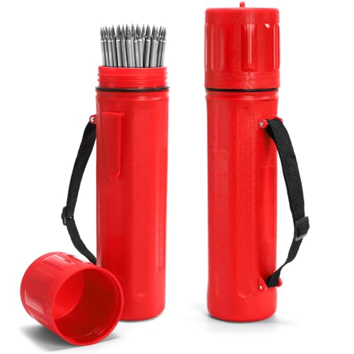
Package includes 2 welding rod holders in red color. The dimension for each tube is 14.6" H x 3" D. Holds up to 10 lb (4.54kg) capacity of any size rods, eliminating the hassles of misplaced rods and offering an organized workflow for your welding projects.
Dialing CLAMS for Stick Welding (SMAW)
Stick welding is portable and performs well outdoors because the electrode coating generates shielding and slag. That does not mean every stick electrode can weld through contamination. Remove oil, moisture, paint, heavy rust, and loose scale. Use an electrode specifically suited to the base metal, position, polarity, and required properties.
Set current from the electrode package or manufacturer data sheet. Do not calculate amperage from rod diameter alone. Hold a short, controlled arc, use the specified drag or travel angle, and begin with a stringer unless the joint or WPS requires a weave or whip technique.
Low-hydrogen electrodes require proper storage and handling. Follow the manufacturer’s exposure and reconditioning instructions rather than assuming an electrode is usable because it looks dry.
MIG Welding Parameters (GMAW)
MIG is common in automotive, fabrication, maintenance, and production work. Conventional MIG uses a constant-voltage power source. Wire-feed speed has a strong effect on current, while voltage influences arc length and bead profile.
For solid ER70S-6 steel wire, DCEP is common, but confirm the wire and machine instructions. Short-circuit transfer is widely used on sheet metal and out-of-position joints. Spray and pulsed spray require suitable wire, shielding gas, current, voltage, CTWD, machine capability, and position.
Maintain the CTWD recommended for the transfer mode. About 3/8 inch is a common short-circuit starting point. A much longer or inconsistent CTWD changes resistance heating in the wire and can reduce current, destabilize the arc, or cause poor fusion.
Here are safer baseline choices for ER70S-6 wire:
| Thickness | Common Wire Choice | Likely Transfer Approach | Starting Method |
|---|---|---|---|
| 16 gauge | .023- or .030-inch ER70S-6 | Short-circuit transfer | Use the machine door chart for the exact gas, wire, and joint; confirm on matching scrap and use short welds where distortion is a concern. |
| 1/4 inch | .035- or .045-inch ER70S-6, subject to machine capacity | Multipass short circuit, spray, or pulsed spray as permitted by the joint, gas, position, and procedure | Use the manufacturer chart or WPS. Do not copy a generic voltage and wire-speed pair without matching all listed conditions. |
Many modern machines have synergic or automatic modes that coordinate voltage and wire-feed speed. These features provide a starting point, but the operator must still verify CTWD, work angle, travel angle, gas coverage, joint preparation, and finished bead quality.
TIG Welding Parameters (GTAW)
TIG provides precise control for steel, stainless steel, aluminum, nickel alloys, and many other metals. A nonconsumable tungsten electrode creates the arc, and filler is added separately when required.
DCEN is the common TIG polarity for steel and stainless steel. AC is the normal starting choice for TIG welding aluminum because the alternating cycle provides oxide-cleaning action while welding. Specialized procedures can differ, so the machine manual and WPS still control.
For 1/8-inch steel, a maximum-current setting around 100–150 amps can be a practical starting range on many machines, but the actual pedal or fingertip output may stay below that maximum as the puddle forms. Joint design, fit-up, travel speed, filler size, and heat sinking can change the needed current.
Hold the tungsten about 1/16 to 1/8 inch from the work. Use roughly a 70- to 80-degree torch angle, which creates a small push angle, and feed filler into the leading edge of the puddle. If the tungsten touches the puddle or filler, stop and correct the contamination.
For aluminum, clean the joint with a suitable degreaser and a dedicated stainless-steel brush used only for aluminum. Choose 4043, 5356, or another filler from a verified alloy-selection chart. Do not make the choice solely by color, availability, or a fixed current rule.
Why Base Metal Prep Matters Before Tweaking Settings
You can dial in CLAMS carefully and still produce a defective weld if the base metal is contaminated. Oil, moisture, paint, plating, rust, heavy mill scale, and embedded grinding debris can cause porosity, inclusions, unstable arc behavior, or incomplete fusion.
Identify the metal and coating before grinding or heating it. Galvanized steel, stainless steel, lead- or cadmium-bearing coatings, painted components, and unknown alloys can require local exhaust ventilation, respiratory protection, coating removal, or a different work method.
Use clean tools that will not contaminate the alloy. Keep dedicated brushes and abrasives for stainless steel and aluminum. Degrease before abrasive cleaning so the abrasive does not smear oil across the joint.
Warning: Do not use chlorinated brake cleaner, degreaser, or solvent near welding. Ultraviolet energy from the arc can react with some chlorinated vapors and form extremely hazardous decomposition products. Follow the cleaning-product safety data sheet and keep solvent operations away from the welding area.
How to Read Weld Symptoms and Adjust the Parameters
Change one variable at a time after confirming the joint is clean, the consumable is correct, the work lead is secure, and the shielding system is working. Several defects can share the same cause, so avoid diagnosing a weld from appearance alone.
| Symptom | Possible Causes | First Checks |
|---|---|---|
| Electrode sticks or arc repeatedly goes out | Current too low, arc too short, poor work connection, damp or unsuitable electrode | Verify the electrode range, polarity, cables, work clamp, and arc-start technique. |
| Heavy spatter | Arc too long, voltage mismatch, incorrect wire-feed speed, wrong polarity, contamination, or poor shielding | Check polarity, consumable, arc length or CTWD, gas, and manufacturer settings. |
| Undercut at the toes | Excessive current or voltage, long arc, excessive travel angle, travel too fast, or poor manipulation | Correct angle and arc length first, then fine-tune output and travel speed. |
| High, rope-like bead | Insufficient heat, excessive travel speed, poor work angle, long MIG stickout, or inadequate sidewall fusion | Confirm the joint is clean and watch whether both joint faces melt before the puddle passes. |
| Burn-through | Excessive heat input, slow travel, large root opening, poor fit-up, or an oversized electrode or wire | Verify fit-up, reduce heat input as appropriate, increase control, and use a backing or sequence approved for the joint. |
| Porosity | Oil, moisture, coating, wind, gas leak, low or turbulent gas flow, long arc, or damp consumable | Clean the joint, inspect hoses and nozzle, verify gas flow, shield the area, and replace suspect consumables. |
| Slag inclusion | Poor cleaning between passes, low heat, incorrect angle, wide weave, poor bead placement, or trapped slag at a toe | Remove slag completely, improve access and angle, and use narrower beads if allowed. |
| Excessive distortion | High total heat input, long continuous welds, poor sequence, weak fixturing, or unnecessary weld size | Check the specified weld size, use balanced sequencing and suitable tacks, and reduce unnecessary heat. |
Common Welding Parameter Mistakes and Quick Fixes
If current appears too low, do not immediately add 10 or 20 amps. First confirm that the electrode or wire is correct, the work lead is secure, the polarity matches the consumable, and the joint is clean. Then move within the published range in small steps while watching the puddle.
If the arc is too long, shorten it without burying the electrode or tungsten in the puddle. In MIG welding, also confirm that you are controlling CTWD rather than focusing only on the visible arc.
A poor torch angle often comes from body position. Dry-run the joint before striking the arc. Make sure you can see both toes, support your hands, and move through the entire weld without twisting your wrist into an extreme angle.
If a weave becomes too wide, return to stringer beads or a narrower oscillation. Clean every slag-producing pass before depositing the next bead. Do not cover undercut, trapped slag, or incomplete fusion with another pass.
In short-circuit MIG, irregular popping can result from an incorrect balance between wire-feed speed and voltage, but gas problems, contact-tip wear, feeding resistance, contamination, and an inconsistent CTWD can sound similar. Check the complete system.
Tacks, clamps, backstepping, skip welding, and a balanced sequence can reduce distortion, but tack spacing and sequence must match the joint. Do not apply a fixed four-inch spacing to every project.
Step-by-Step: Setting Up Parameters for Your Next Weld
- Assess the job. Identify the base metal, alloy, thickness, joint type, welding position, service conditions, and required weld size. For regulated work, obtain the drawing, WPS, and applicable inspection criteria.
- Select the process and filler. Choose the electrode, wire, filler rod, shielding gas, and diameter that match the base metal, position, machine capacity, and required properties.
- Prepare a safe work area. Remove flammables, provide ventilation, inspect leads and hoses, secure gas cylinders, install welding screens, and wear the required PPE.
- Prepare and fit the joint. Remove contamination and coatings using an approved method. Set the bevel, root face, root opening, alignment, and tacks according to the drawing, tested procedure, or WPS rather than a universal gap.
- Set polarity and supporting controls. Confirm polarity, shielding gas, flow rate, wire-feed system, tungsten preparation, AC balance, pulse controls, or other process-specific settings.
- Enter the starting output. Use the machine chart, consumable data sheet, welding calculator, or WPS. Confirm that the machine has enough output and duty cycle for the planned weld.
- Run a test bead. Use matching scrap in the same position where practical. Establish the correct arc length or CTWD, work angle, travel angle, manipulation, and speed.
- Adjust one variable at a time. Make small changes and record the result. Do not compensate for dirty metal or poor fit-up by simply increasing current.
- Weld the joint. Watch the leading edge and toes of the puddle, maintain a stable posture, clean between slag-producing passes, and stay within the procedure limits.
- Inspect the work. Check weld size, profile, tie-in, crater fill, undercut, overlap, cracks, porosity, arc strikes, and distortion. Remember that visual inspection cannot confirm the absence of internal defects when additional testing is required.
Always run a test bead on matching scrap when the procedure allows it. For structural, pressure, pipeline, lifting, vehicle-safety, or other critical work, a visually attractive bead is not proof that the weld meets the required code or design strength.
Products Worth Considering

𝐏𝐫𝐨𝐟𝐞𝐬𝐬𝐢𝐨𝐧𝐚𝐥-𝐆𝐫𝐚𝐝𝐞 𝐋𝐞𝐧𝐬 𝐂𝐨𝐚𝐭𝐢𝐧𝐠: Compared to standard safety glasses, our premium coating delivers superior performance: impact-resistant, scratch-resistant, and acid/alkali-resistant on the outside, with an advanced anti-fog treatment on the inside to maintain clear vision in changing temperature and humidity conditions. Durable and easy to clean – simply rinse with water and wipe dry.

Premium Goatskin Leather: Crafted from high-quality goatskin leather, these gloves offer a superior combination of flexibility and durability. The soft leather provides excellent dexterity while ensuring long-lasting wear.

【MULTI-USE】This CAT 2 AR/FR, NFPA2112 compliant shirts is part of your PPE system. Designed for workers who may be exposed to potential flash fire and arc flash hazards. Self-extinguish garments can help prevent or reduce the severity of burn injuries for added protection.
Frequently Asked Questions
What happens if my welding current is too low?
The electrode may stick, the arc may be unstable, and the bead may have poor toe wetting or incomplete fusion. Confirm polarity, cable connections, consumable condition, and joint cleanliness before increasing current. Then move upward within the published electrode, wire, or WPS range in small steps.
How do I know if my arc length is too long?
Possible signs include an unstable or harsh arc, excess spatter, reduced shielding, undercut, and a bead that becomes wider or less controlled. In stick welding, shorten the arc toward the electrode manufacturer’s recommended distance. In TIG, keep the tungsten close without touching. In MIG, check arc behavior and CTWD separately.
What’s the best angle for welding a fillet joint?
For an equal-leg fillet in a 90-degree T-joint, begin with a work angle near 45 degrees so the arc is directed into both members. Add the process-appropriate travel angle, often around 5–15 degrees. Unequal thickness, unequal weld legs, position, and access can require a different work angle.
Why is my weld bead too narrow?
Excessive travel speed is one possible cause, but low heat, a long MIG stickout, incorrect work angle, insufficient voltage, or poor manipulation may also create a narrow bead. Watch whether the joint faces melt before the puddle moves past them, and change only one verified variable at a time.
Can I use the same parameters for aluminum and steel?
No. Aluminum and steel require different polarity choices, filler metals, cleaning methods, shielding practices, heat control, and machine settings. Do not reduce a steel amperage by a fixed percentage. Use an aluminum-specific chart or procedure and select filler according to the exact base-alloy combination and service requirements.
Do the CLAMS parameters replace a welding procedure specification?
No. CLAMS is a technique checklist. A WPS can specify the permitted process, base metal, filler, polarity, current, voltage, travel speed, position, preheat, interpass temperature, shielding gas, joint design, and other essential limits. The WPS governs when one is required.
Should I push or pull when MIG welding?
Either can be appropriate in short-circuit MIG when the wire and procedure permit it. Pushing commonly creates a flatter, wider bead and gives a better view ahead of the puddle. Pulling often produces a narrower bead with more buildup. Spray and pulsed procedures commonly use a push angle, while flux-cored wires frequently require a drag technique. Follow the consumable instructions.
Sources
- Miller — Five Steps to Improving Your Stick Welding Technique — CLAMS technique, arc length, angles, manipulation, and travel speed.
- Miller — Understanding the Basics of MIG Welding for Mild Steel — wire stickout, travel angle, work angle, and machine-setting variables.
- Miller — Guide to TIG Welding Basics — TIG polarity, torch position, tungsten selection, arc length, and troubleshooting.
- Lincoln Electric — Excalibur 7018-1 MR — manufacturer operating-current ranges for E7018 electrodes.
- OSHA 29 CFR 1910.252 — Welding, Cutting, and Brazing — fire prevention, ventilation, confined-space, coating, and cleaning-solvent precautions.
- American Welding Society — AWS D1.1/D1.1M:2025 — current structural-steel welding code scope and edition.