
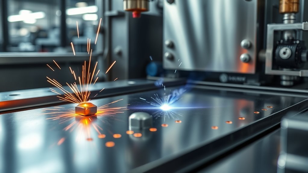
Projection welding is a resistance welding process that concentrates current and force at raised features on one part. Those projections heat and collapse to form one or more welds. The process is widely used for weld nuts, studs, brackets, crossed wires, and repeatable sheet-metal assemblies, but dependable results require controlled part geometry, tooling, machine settings, and inspection.
Quick Answer
Projection welding is a resistance welding method in which raised points, rings, or natural contact features focus electrical current and electrode force. The projections heat, soften, and collapse to create weld nuggets. It is best suited to repeatable production joints such as weld nuts, studs, brackets, wire grids, and multi-point assemblies.
Key Takeaways
- Projection welding uses resistance heat, electrode force, and a timed current pulse; it normally needs no filler metal or shielding gas.
- The projection defines the initial contact area and helps control where the weld forms.
- Projection shape, equal height, part fit-up, machine rigidity, electrode alignment, and force follow-up are as important as current and weld time.
- There is no universal projection size or weld schedule. Settings must be developed and verified on the actual material, coating, thickness, fastener, and production machine.
- Critical welds need documented acceptance criteria and regular destructive or mechanical verification, supported by process monitoring where appropriate.
- Only properly instructed and competent personnel should operate resistance-welding equipment, with guards, interlocks, ventilation, and maintenance controls in place.
What Is Projection Welding?
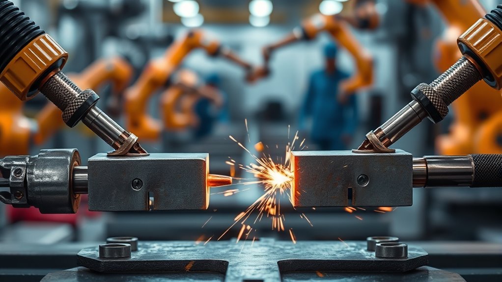
Projection welding is a specialized resistance welding process. Small raised features on one component create the first contact points between the parts. When the electrodes clamp the assembly and current flows, the projections create high local current density and heat. The heated projections deform under force, and a weld forms at each planned location.
The process is used in automotive, appliance, electrical, hardware, and wire-product manufacturing. Common parts include weld nuts, studs, bosses, clips, brackets, reinforcements, crossed wires, wire mesh, and sealed electronic packages. The American Welding Society’s projection welding handbook chapter covers its equipment, materials, variables, schedules, quality, applications, limitations, economics, and safety.
Projection welding is not an arc process. It does not create an open welding arc, and it normally does not use filler wire or shielding gas. The joint forms from resistance heating at the part interface while the electrodes apply force and carry current.
How Projection Welding Works
A projection weld is made through a short, controlled sequence. Exact timing and control names vary by machine, but the basic cycle is the same:
- Load and locate the parts. The fixture or locating pin positions the components and supports them against movement.
- Apply squeeze force. The electrodes close and reach a stable force before current starts.
- Pass welding current. Current follows the restricted path through the projections, producing concentrated heat at the interface.
- Allow controlled collapse. The heated projections soften and shorten while the welding head follows their movement and maintains force.
- Form the weld nugget or fused zone. Heat and pressure create the joint at each projection.
- Hold under force. Current stops, but electrode force remains while the weld cools and solidifies.
- Release and inspect. The electrodes open, the part is unloaded, and required visual or production checks are completed.
Warning: Projection welders combine high current, powerful clamping motion, hot metal, and sometimes stored electrical energy. Keep guards and interlocks in service, follow lockout procedures for maintenance, and do not operate the equipment unless you have been properly instructed and judged competent.
Why the Projection Heats First
Resistance heating is often described with the relationship heat is proportional to current squared × resistance × time. In a real weld, resistance changes rapidly as coatings break down, surfaces heat, and the projection collapses. That is why a projection weld cannot be controlled by current alone.
| Control | What It Changes | Typical Risk When Incorrect |
|---|---|---|
| Projection geometry | Initial contact area, heat location, and collapse behavior | Uneven heating, premature collapse, or an undersized weld |
| Electrode force | Contact resistance, containment, and projection collapse | Expulsion at low force or flattened projections at excessive force |
| Current and weld time | Rate and amount of heat input | Weak bonding, excessive indentation, thread damage, or expulsion |
| Squeeze time | How long the machine stabilizes force before current | Arcing, splash, or inconsistent contact |
| Hold time | Cooling under force | Movement, cracking, or loss of joint consistency |
| Mechanical follow-up | How well the head maintains force as the projection shortens | Force loss and expulsion during rapid collapse |
Projection Collapse and Weld Solidification
The projection should collapse in a controlled way while the weld forms. The machine frame, ram, tooling, and electrodes must remain aligned and maintain force as the joint thickness changes. After current stops, hold time keeps the assembly under pressure while the fused zone cools.
A visually flattened projection does not prove that a sound weld formed. Production settings should be established with test parts and verified by the required torque, push-out, peel, sectioning, or other acceptance test.
A repeatable projection weld is a system result: part geometry, material condition, tooling, force response, power delivery, cooling, and inspection must work together.
Projection Welding Projections and Joint Design
The projection is not merely a bump in the metal. It is a designed current and force concentrator. Its shape, height, base width, position, spacing, material hardness, and manufacturing tolerance affect how the joint heats and collapses.
Common projection types include:
- Embossed projections: formed in sheet by stamping, pressing, or coining.
- Machined or coined projections: made on thicker or solid components where tighter control is needed.
- Ring or annular projections: used around an opening or package perimeter when a circular or continuous weld path is required.
- Fastener projections: nibs, bosses, or rings built into weld nuts, studs, and threaded fittings.
- Natural projections: existing geometry, such as two wires crossing at a point.
Products Worth Considering

Durable Material: ARCCAPTAIN electrode holder is made of high quality copper as well as insulating materials to ensure high efficiency and safety while welding.
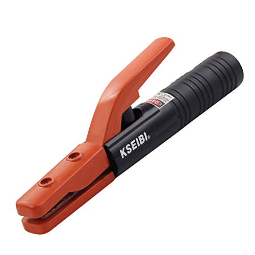
This Electrode holder is Made from high quality materials for high conductivity and improved cable connections. Supplied with an allen wrench and cable connection ferrule, assuring efficient connnection and minimizing cable strand breakage at the connection.

Projection Design Factors
- Equal height: Multiple projections should contact the mating part as evenly as practical so one point does not take most of the current and force.
- Stable base: The surrounding sheet or fastener body must support the projection without buckling or distorting before the weld forms.
- Adequate spacing: Projections placed too close together can divide current and force unevenly.
- Edge distance: Projections near an unsupported edge may distort the part or produce an incomplete weld.
- Collapse allowance: Tooling and locators must allow the moving electrode to follow the shortening joint without binding.
- Thread protection: Weld-nut and stud tooling should prevent misalignment and keep weld splash away from usable threads.
Note: There is no universal diameter-to-height ratio for every projection. Embossed sheet projections, annular projections, weld-nut nibs, crossed wires, and sealed packages use different geometries. Start with the applicable part or fastener standard, machine supplier guidance, and a qualified weld-development plan rather than a generic ratio.
Materials, Coatings, and Surface Condition
Projection welding is most straightforward when the parts are electrically conductive, compatible with resistance welding, and consistent in thickness and surface condition. Low-carbon steel and coated low-carbon steel are common production materials. Stainless steel, aluminum, copper alloys, high-strength steel, and dissimilar combinations may also be possible, but they can require different electrodes, power supplies, force response, and acceptance testing.
Coatings change contact resistance and heat balance. Zinc, galvanneal, aluminum-silicon, paint, primer, oil, scale, and plating should not be treated as interchangeable. ISO 16432:2006 covers embossed projection welding for specified uncoated and metallic-coated low-carbon steels, but it does not cover organic-coated or primer-coated steels. Always confirm the material and coating in the drawing, supplier data, and qualified procedure.
Pro Tip: For weld nuts and studs, inspect more than attachment strength. Verify thread condition, hole alignment, seating, distortion, and the failure mode at every projection. A fastener can pass a quick visual check and still fail assembly or service requirements.
Projection Welding Equipment and Setup
A projection-welding system normally includes a power supply and control, transformer or stored-energy circuit, welding head or press, electrodes, fixture, part locators, cooling system, and safety controls. The machine must provide enough current and force without operating at the edge of its capacity.
Products Worth Considering

💥【What You Get】------ In this kit, you will receive a weld nuts set which comes with 10pcs M10 black weld nuts, the length is 0.5 inches (14mm) and the width is 0.7 inches (18mm), in total of 10pcs. Weld nut can install the caster and connect threaded. Sufficient quantity for you to apply in your daily life or work. Wonderful products can't be missed.
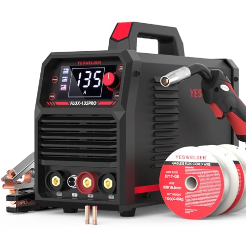
READY OUT OF THE BOX: Start welding immediately! It masterfully handles Gasless Flux Core MIG, Stick, and Lift TIG (Extra Lift TIG torch required). This budget-friendly 3-in-1 machine includes extra E71T-GS .030''&.035'' flux core wires, known for its smooth arc and high feedability. Say goodbye to heavy shielding gas cylinders—perfect for outdoor, windy, or all-position welding.

【200Amp Power for Home Repairs & DIY】 This 110V stick welder Adjustable Current: 20-200A. Easily weld metal materials with 0.06-0.2 inch thickness, such as cast iron, mild steel, etc. For stainless steel, use E308L-16 rods only. Includes 20 welding rods right out of the box, so you can start your first project immediately.
Power Supply Options
| Power Type | General Characteristic | Where It May Fit |
|---|---|---|
| AC | Line-frequency current controlled by cycles or portions of cycles | Many conventional steel projection-welding applications with suitable current and force capacity |
| MFDC or inverter DC | Faster electronic control and feedback than conventional line-frequency AC | Automated applications that benefit from precise current control and process monitoring |
| Capacitor discharge or stored energy | Stores energy and releases it in a short pulse | Applications needing rapid localized heating, provided the frame and follow-up system can maintain force during fast collapse |
No power-supply type is automatically best for every part. Material resistance, coating, projection mass, required pulse shape, machine stiffness, available force, follow-up speed, electrical service, and production rate all affect the choice.
Electrodes, Fixtures, and Cooling
Projection welding commonly uses broad, flat electrode faces because the part geometry defines the weld location. The electrode material and face design must carry current, resist deformation, support the work, and remove heat without damaging the part. Weld-nut tooling often uses an insulated locating pin so current does not bypass the intended projections.
Fixtures should locate the part without rocking, support thin sheet around the weld, and keep the load centered under the ram. Water-cooled electrodes and tooling must have adequate flow, and leaks or blocked passages should be corrected before production continues.
When to Use Projection Welding
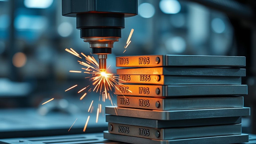
Use projection welding when the part can include a reliable projection and the process benefits from fast, repeatable joining. It is especially useful when fixtures can control alignment and when one machine stroke can make several welds.
Best Applications
- Weld nuts and studs: attaching threaded hardware to sheet metal for later assembly.
- Brackets, clips, and reinforcements: making localized joints without a long arc-weld bead.
- Cross-wire products: joining racks, baskets, screens, and mesh where wire crossings act as natural projections.
- Multi-point assemblies: making several welds in one cycle when projection height and force distribution are controlled.
- Ring-welded components: joining circular or perimeter features in selected sealed or structural assemblies.
- Mixed-thickness stacks: joining compatible conductive parts after testing confirms heat balance and strength.
When Not to Use Projection Welding
Projection welding may be a poor choice when the part cannot hold a repeatable projection, the joint cannot be reached by opposed electrodes, the assembly cannot be clamped and supported, or production volume does not justify the tooling and process development.
Choose another process when the joint needs a long continuous structural bead, field-repair flexibility, one-sided access without specialized equipment, or a material combination that cannot be qualified with available power, force, tooling, and inspection methods.
Process Advantages
- Fast cycle time: Multiple projections can be welded in one cycle when current and force divide evenly.
- No added filler: The joint normally forms from the base materials alone.
- Defined weld location: Part geometry establishes the planned weld points.
- Localized heating: Focused heat can limit overall distortion when the schedule is correct.
- Broad electrode faces: Larger supporting electrodes can reduce visible marking and may improve electrode life in suitable applications.
- Automation potential: Feeders, fixtures, sensors, and weld controls can support high-volume production.
The tradeoff is tighter control of part design, tooling, projection tolerance, machine response, and preventive maintenance. A small error can repeat across an entire production batch.
Projection Welding vs Spot Welding
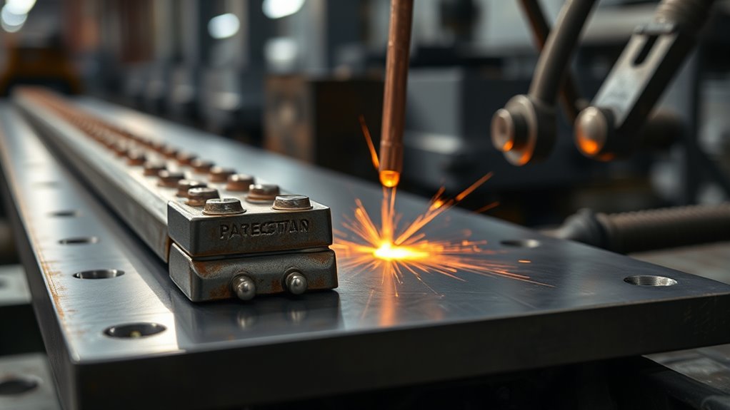
Projection welding and resistance spot welding both use current and electrode force, but they define the weld area differently. Spot welding relies mainly on electrode-tip location and face size. Projection welding relies on a raised or naturally restricted feature in the workpiece.
| Factor | Projection Welding | Spot Welding |
|---|---|---|
| Weld location | Set by projections or natural contact points | Set mainly by electrode-tip position |
| Typical uses | Fasteners, bosses, brackets, crossed wires, and multi-point joints | Overlapping sheet-metal lap joints |
| Electrode shape | Often broad and flat to support the part | Usually has a defined tip face that helps establish weld size |
| Part preparation | Requires controlled projection geometry or a natural projection | Usually requires a suitable lap stack and electrode access |
| Multi-weld potential | Several projections can weld in one press cycle | Often one spot per gun, unless multi-spot equipment is used |
| Main control challenge | Equal projection contact, collapse, and force distribution | Tip condition, shunting, fit-up, and sheet-stack consistency |
Use projection welding when a fastener, boss, ring, or designed contact point should define the weld. Use spot welding for simpler overlapping sheets when projections are unnecessary.
How to Develop and Control a Projection-Weld Schedule
A weld schedule is the documented combination of force, current or energy, timing, pulse shape, electrode arrangement, cooling, and part conditions used to produce an acceptable joint. Do not copy a schedule from a different fastener, coating, sheet thickness, or machine without verification.
- Define the requirement. Record the material, coating, thickness, fastener or projection standard, joint load, appearance limits, thread requirements, and required tests.
- Confirm machine capability. Check current, force, duty cycle, frame stiffness, ram travel, follow-up response, electrode cooling, and control resolution.
- Inspect trial parts. Measure projection height and uniformity, fit-up, flatness, hole location, surface condition, and coating lot.
- Establish safe starting settings. Use applicable standards, fastener data, and machine-supplier guidance as starting points.
- Run controlled trials. Change one main variable at a time and record current, force, time, displacement, expulsion, indentation, and part condition.
- Test the joint. Use the specified torque, push-out, peel, cross-section, leak, or load test and confirm the required failure mode.
- Find a stable operating window. Verify that acceptable welds are produced across expected part, coating, voltage, cooling, and electrode-wear variation.
- Document and lock the process. Record approved limits, setup checks, inspection frequency, reaction plan, and maintenance triggers.
ISO 15614-12:2021 addresses qualification testing for spot, seam, and projection welding procedures. Product drawings, customer specifications, applicable codes, and contract requirements still control the final acceptance criteria.
Key Process Variables
- Electrode force: Low force can allow expulsion; excessive force can crush the projection before enough heat develops.
- Weld current or energy: Too little produces weak bonding; too much can cause splash, indentation, overheating, or thread damage.
- Weld time and pulse shape: The current must heat the interface before the projection loses its concentrating effect.
- Squeeze time: Force should be stable before the weld pulse begins.
- Hold time: Pressure remains after current stops so the joint can solidify.
- Electrode alignment and condition: Worn, dirty, tilted, or overheated tooling changes force and current paths.
- Part fit-up: Gaps, burrs, rocking, distorted sheet, and unequal projections can make one weld form before the others.
- Cooling: Changing water temperature or flow can alter electrode condition and process stability.
Common Defects and Troubleshooting
Use troubleshooting as a structured process. Confirm the defect with the required test, then check part geometry, force, current, timing, tooling, cooling, and material condition. Do not correct every problem by simply increasing current.
| Problem | Likely Causes | Checks and Corrective Direction |
|---|---|---|
| Weak weld or loose fastener | Low heat input, poor fit-up, unequal projections, contamination, or force loss | Verify the test method, clean and measure parts, check force and follow-up, inspect electrodes, then re-establish the approved schedule |
| Expulsion or heavy sparks | Excessive current or energy, low force, short squeeze time, poor alignment, coating variation, or slow follow-up | Confirm stable force before current, check ram response and alignment, inspect coating and projection height, and reduce excessive heat input within the qualified window |
| Projection flattens before welding | Excessive force, weak or over-tall projection, soft fastener, or unsupported sheet | Run a no-current force check, review projection design and material hardness, improve support, and requalify the schedule |
| Nut or stud misalignment | Worn locator, bent pin, poor feeder placement, fixture movement, or off-center force | Inspect locating hardware, fixture repeatability, part feeding, ram alignment, and hole position |
| Thread damage or weld splash in threads | Excess heat, long weld time, inadequate locating-pin protection, or heavy expulsion | Check thread gauges, locator insulation, force, follow-up, and pulse duration; correct expulsion before resuming production |
| Electrode sticking or rapid wear | Overheating, wrong electrode material, poor cooling, contamination, or excessive current density | Check water flow and temperature, clean parts, verify electrode alloy and face condition, and review the schedule |
| Uneven multi-projection welds | Unequal height, warped parts, uneven force distribution, shunting, or fixture deflection | Measure every projection, check flatness and tool parallelism, support the sheet, and verify current and force balance |
| Good appearance but failed strength test | Surface collapse without adequate fusion, incorrect acceptance test, or process drift | Section a sample, review the failure mode, compare monitored data with the approved baseline, and stop relying on appearance alone |
Projection Welding Pros and Cons
Projection welding can improve speed and consistency, but only when the joint and production system are designed for it.
| Pros | Cons |
|---|---|
| Can form several welds in one cycle | Requires controlled projection geometry and contact |
| Well suited to nuts, studs, brackets, bosses, and wire products | Tooling, locating, and process development add upfront cost |
| Normally needs no filler metal or shielding gas | Not ideal for changing, low-volume field repair |
| Localized heating can limit overall distortion | Coatings, hardness, flatness, and lot variation can narrow the process window |
| Broad electrodes can support the part and reduce marking | Machine stiffness, follow-up, cooling, and electrode maintenance remain critical |
| Integrates well with automation and monitoring | Hidden welds require planned verification rather than visual inspection alone |
Common Projection Welding Applications by Industry
Projection welding appears in many production settings where localized heat, short cycle time, and repeatable placement matter.
- Automotive: weld nuts, studs, fastener plates, reinforcements, brackets, filters, and selected brake or chassis-related parts.
- Appliances: brackets, tabs, mounting hardware, frames, and reinforcements.
- Wire products: racks, baskets, grilles, guards, mesh, and screens.
- Electrical and electronics: terminals, contact assemblies, enclosures, and ring-projection package seals where the design is qualified.
- General hardware: bosses, threaded fittings, clips, hinges, and stamped subassemblies.
Because several projections can be welded in one cycle, the process can reduce assembly time. The best results come when the projection, tooling, machine, inspection plan, and downstream assembly requirement are developed together.
Projection Welding Safety
Projection welding may not produce a bright open arc, but it still creates serious hazards. These include pinch and crush points, flying sparks or expelled metal, hot parts, electrical energy, stored capacitor energy, moving feeders, water leaks near electrical equipment, and fumes from coatings or contamination.
OSHA 29 CFR 1910.255 requires resistance-welding operators to be properly instructed and judged competent. It also addresses guarded controls and foot switches, point-of-operation guarding, spark shields, interlocked access panels, grounding where technically practical, emergency stops on specified multispot equipment, and periodic inspection by qualified maintenance personnel. General welding ventilation and fire-prevention requirements appear in OSHA 29 CFR 1910.252.
- Use the required eye and face protection for sparks, hot particles, and the specific operation.
- Keep hands clear of electrodes, clamps, locators, feeders, and moving fixtures.
- Do not bypass two-hand controls, light curtains, interlocks, guards, emergency stops, or grounded circuits.
- Use effective ventilation for coated, plated, oily, painted, or contaminated materials, and follow the material-specific hazard assessment.
- Keep combustible materials away from expelled metal and provide shields for nearby workers.
- Follow lockout/tagout and stored-energy discharge procedures before servicing the machine.
- Stop production for damaged cables, leaking cooling lines, overheated tooling, unusual noise, repeated expulsion, or failed safety devices.
How Projection Welds Are Inspected and Verified
The weld is hidden between the parts, so appearance alone is not enough for a critical joint. The inspection plan should match the drawing, customer requirement, load, failure consequence, and qualified weld procedure.
| Method | What It Can Confirm | Important Limit |
|---|---|---|
| Visual and dimensional inspection | Position, seating, alignment, indentation, expulsion, distortion, and thread condition | Cannot directly prove hidden fusion or strength |
| Torque, push-out, or pull test | Fastener attachment strength and failure behavior | Test setup and minimum value must come from the applicable requirement |
| Peel, chisel, or destructive separation | Weld button or parent-metal failure at individual projections | Destroys the sample and may not suit every geometry |
| Macro section | Fusion-zone shape, penetration, cracks, voids, and projection collapse | Represents only the sectioned location and requires careful preparation |
| Leak testing | Seal performance of qualified annular or package welds | Does not replace structural acceptance tests unless the specification says so |
| Validated nondestructive examination | Selected internal conditions when the joint and method are suitable | Ultrasonic, radiographic, thermographic, or other methods must be proven for the actual geometry and defect types |
| Process monitoring | Changes in current, voltage, force, displacement, resistance, timing, or energy | Monitoring detects deviation; it does not automatically prove weld strength without correlation to tested parts |
For production control, combine periodic destructive or mechanical testing with setup verification, electrode maintenance, part checks, and monitored process limits. A reaction plan should state when to stop the machine, quarantine parts, correct the cause, and revalidate the weld.
Frequently Asked Questions
What is projection welding used for?
Projection welding is used for weld nuts, studs, bosses, brackets, clips, reinforcements, crossed wires, wire grids, and selected ring-welded parts. It is most useful when parts and fixtures are repeatable and one or more welds must be made quickly in a controlled production process.
Is projection welding easy to learn?
The principle is simple, but safe production operation requires machine-specific training. Operators must understand guards, controls, fixtures, part loading, approved weld limits, quality checks, emergency stops, and the response to expulsion or failed tests.
Can projection welds be inspected?
Yes. Common methods include visual and dimensional checks, torque or push-out tests for fasteners, peel or destructive separation, macro sections, leak tests for sealed parts, and process monitoring. Specialized nondestructive methods may be used only after they are validated for the joint.
What are the different types of projection welding?
Common forms include embossed projection welding, machined or coined projection welding, annular or ring projection welding, weld-nut and weld-stud projection welding, and cross-wire welding. Each uses a restricted initial contact area to focus heat and force.
What is the difference between projection welding and resistance spot welding?
Both use resistance heat and electrode force. Spot welding mainly uses the electrode tip to define the weld area. Projection welding uses a raised or natural feature in the part, making it especially useful for fasteners, bosses, crossed wires, and multiple welds in one cycle.
Does projection welding need filler metal or shielding gas?
No. Projection welding normally forms the joint from the base materials and does not use filler metal or shielding gas. Ventilation may still be required because heated coatings, oils, plating, or contamination can produce hazardous fumes.
What causes projection-weld expulsion?
Common causes include excessive current or energy, low or unstable force, short squeeze time, poor electrode alignment, unequal projection height, coating variation, and a welding head that cannot follow rapid projection collapse. The cause should be verified before changing settings.
Can I use a generic projection-welding settings chart?
A chart can provide a starting point only when it matches the fastener, material, coating, thickness, electrode arrangement, and machine type. Final settings must be tested on real production parts and documented with the required strength and quality checks.
Conclusion
Projection welding is a fast, controlled resistance welding method for parts that include reliable raised or natural contact points. It is especially effective for weld nuts, studs, brackets, bosses, reinforcements, crossed wires, and multi-point assemblies. Compared with spot welding, the part geometry—not only the electrode tip—defines where heat and force are concentrated.
Strong, repeatable welds depend on the complete system: projection design, material and coating, part fit-up, electrode force, current or energy, timing, machine rigidity, follow-up response, cooling, inspection, and maintenance. Develop the schedule on actual parts, qualify it against the governing requirement, and keep safety devices and process controls in service throughout production.
Sources
- American Welding Society: Projection Welding — process fundamentals, equipment, variables, applications, quality, and safety.
- AMADA WELD TECH: Projection Welding — manufacturer explanation of projection features, current paths, heat balance, and electrode life.
- ISO 16432:2006 — procedure requirements and material scope for embossed projection welding of specified low-carbon steels.
- ISO 15614-12:2021 — qualification testing for spot, seam, and projection welding procedures.
- OSHA 29 CFR 1910.255: Resistance Welding — operator competence, guarding, interlocks, shields, grounding, and inspection requirements.
- OSHA 29 CFR 1910.252: General Welding Requirements — ventilation, fire prevention, eye protection, and general welding controls.




