
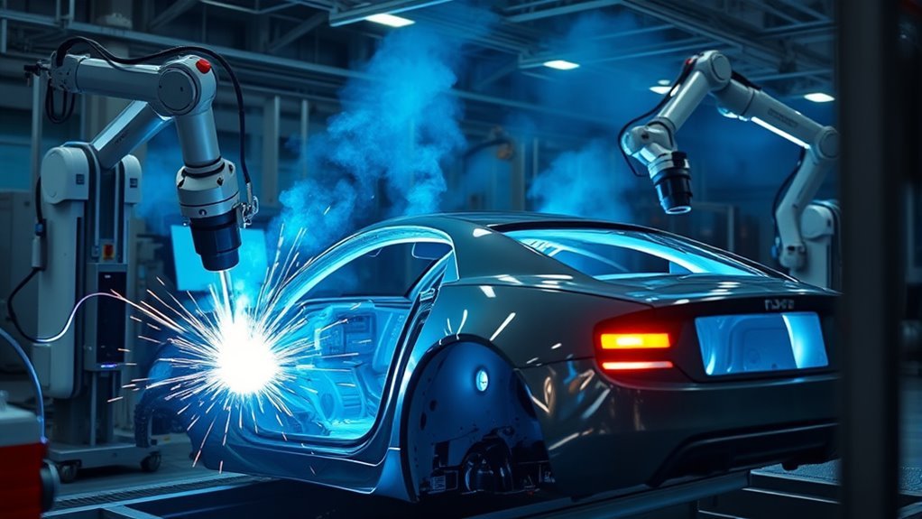
Robotic welding is one of the main reasons modern vehicle plants can join large numbers of parts at a steady pace. A robot can repeat the same motion, gun force, travel speed, and weld settings across many cycles. The result depends on more than the robot arm, though. Fixtures, welding equipment, sensors, inspection, maintenance, and trained people all affect the finished joint.
Quick Answer
Robotic welding in car manufacturing uses programmed industrial robots to make resistance spot, arc, laser, and other welds on repeatable vehicle parts. Automakers use it mainly for body-in-white, frame, underbody, seat, exhaust, suspension, and electric-vehicle components because it can improve consistency, throughput, traceability, and worker protection.
Key Takeaways
- Resistance spot welding is a core process for joining overlapping body panels in body-in-white production.
- MIG/MAG and TIG are arc-welding processes, not separate alternatives to arc welding; robotic TIG is usually reserved for narrower, lower-volume needs.
- A stable fixture, correct part fit-up, maintained electrodes or torch parts, and validated weld settings matter as much as robot accuracy.
- Process monitoring can flag abnormal conditions, but it does not automatically prove that every weld is sound.
- People still program cells, approve weld procedures, inspect parts, maintain equipment, and control hazardous energy.
At a Glance
| Primary Automotive Use | Repeatable joining of body, chassis, underbody, seat, exhaust, suspension, and EV parts |
| Common Processes | Resistance spot welding, MIG/MAG arc welding, laser welding or brazing, stud welding, and selected TIG applications |
| Main Quality Inputs | Part fit-up, fixture accuracy, weld schedule, tool condition, material coating, shielding, calibration, and inspection |
| Main Limits | High integration cost, sensitivity to variation, maintenance needs, changeover work, and the need for skilled oversight |
What’s in This Article
- What Is Robotic Welding in Car Manufacturing?
- What Makes Up a Robotic Welding Cell?
- How Does Robotic Welding Work on the Line?
- What Types of Robotic Welding Do Auto Plants Use?
- How Do the Main Robotic Welding Processes Compare?
- Why Do Automakers Use Robotic Welding?
- What Parts Get Robotic Welding Most Often?
- How Is Robotic Welding Used in Body, Frame, and Underbody Assembly?
- How Do Auto Plants Control Robotic Weld Quality?
- Where Does Robotic Welding Still Need People?
- What Safety Controls Do Robotic Welding Cells Need?
- What Challenges Do Robotic Welding Systems Face?
- What Maintenance and Troubleshooting Do Robotic Weld Cells Need?
- When Does Robotic Welding Make Economic Sense?
- What’s Next for Robotic Welding in Cars?
- Frequently Asked Questions
What Is Robotic Welding in Car Manufacturing?
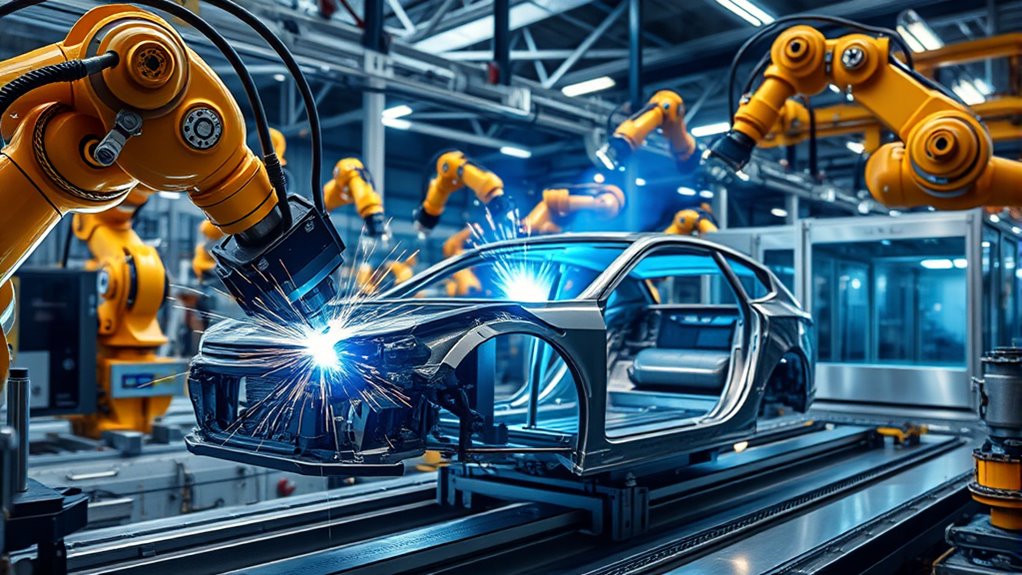
Robotic welding uses a programmed industrial robot to move a welding gun, torch, laser head, or workpiece through a controlled cycle. The controller coordinates robot motion with the welding power source, clamps, positioners, wire feeder, sensors, and safety system.
In automotive plants, the best-known example is resistance spot welding on body-in-white assemblies. Robots also automate MIG/MAG, pulsed MIG, selected TIG, plasma, laser, and stud-welding processes. FANUC’s automotive application guidance lists robotic spot welding and several automated arc-welding processes used for vehicle components.
The main benefit is repeatability. A robot can return to programmed positions and repeat a validated weld schedule without fatigue. That does not mean every weld will be good by default. A shifted part, worn contact tip, dirty electrode, poor ground, wrong recipe, or loose fixture can still produce a defect.
The robot repeats the process it is given. Weld quality still depends on correct parts, tooling, settings, maintenance, and verification.
What Makes Up a Robotic Welding Cell?
A complete cell includes more than a robot arm. OSHA describes an industrial robot system as the manipulator, controller, end effector, power sources, sensors, programs, and communication interfaces that work together. OSHA’s industrial robot safety guidance also treats the surrounding application as part of the hazard picture.
- Robot and controller: Move the weld tool or part along the programmed path.
- Welding equipment: Includes the spot-weld gun, arc-welding power source and wire feeder, laser system, cooling, shielding gas, cables, and consumables required by the process.
- Fixture or positioner: Locates parts, controls gaps, and may rotate the assembly so the robot can reach the joint.
- Tooling and dress package: Carry power, water, air, wire, gas, and signals to the end effector without restricting motion.
- Sensors and controls: Confirm part presence, clamp state, gun force, current, voltage, wire feed, seam position, or other process signals.
- Safety system: Uses guarding, interlocks, safe controls, emergency stops, and hazardous-energy procedures.
- Inspection and data system: Records results, flags abnormal cycles, and links weld data to a part or production batch when traceability is required.
Some cells automatically load and unload parts. Others are semiautomatic, with an operator loading a fixture while the robot performs the weld cycle. The correct layout depends on takt time, part size, reach, process hazards, maintenance access, and how often the product changes.
How Does Robotic Welding Work on the Line?
A robotic weld cycle follows a controlled sequence. The exact steps vary by process, but most automotive cells use the same basic logic: locate the part, confirm the recipe and safety state, execute the weld, check process signals, and release or route the part.
Part Loading and Fixturing
The system places stamped panels, tubes, castings, or other components into a fixture. Locating pins, nests, clamps, and sensors hold the assembly in a known position. Good fixture design controls part gaps and keeps the joint within the robot’s working range.
If the part is not seated correctly, a perfectly programmed robot can still weld in the wrong place. Plants therefore use part-present sensors, clamp confirmation, vision, or dimensional checks before enabling the weld cycle.
Recipe Selection and Path Setup
The controller selects the approved program and weld schedule for the part. Engineers may create paths with a teach pendant, offline programming software, vision guidance, touch sensing, or a mix of these methods.
The weld procedure sets the variables that matter for the process. Spot welding depends on items such as current, weld time, electrode force, squeeze time, and tip condition. Arc welding depends on current, voltage, wire feed, travel speed, torch angle, contact-tip-to-work distance, gas flow, and joint fit-up. Laser welding depends on power, focus, speed, beam position, shielding, and gap control.
Automated Weld Execution
After the part and cell status are confirmed, the robot follows its programmed motion. A spot-weld gun clamps the sheets and sends current through the joint. An arc-welding robot starts the arc and coordinates wire feed with torch travel. A laser system positions and controls the focused beam along the seam.
| Step | Typical Cell Action |
|---|---|
| Verify | Confirm part identity, position, clamp state, recipe, and safety status |
| Weld | Run the approved path and process settings |
| Monitor | Record selected process signals and alarms |
| Decide | Pass the part, route it for inspection, stop the cell, or allow a validated repair cycle |
Monitoring, Inspection, and Traceability
Process monitoring compares measured signals with approved limits. Depending on the system, it may watch current, voltage, resistance, force, displacement, arc stability, seam position, bead shape, or laser-weld images. Advanced systems may adapt selected settings, but many installations only record and flag abnormal conditions.
A normal signal does not always prove that the joint has the required strength. Plants may combine in-process monitoring with visual checks, peel or chisel tests, destructive sectioning, ultrasonic inspection, leak testing, dimensional inspection, or other methods defined by the part-control plan.
Note: “Real-time monitoring” and “closed-loop control” are not the same. Monitoring records or flags a condition. Closed-loop control also changes the process in response, and it must be validated for the specific weld.
What Types of Robotic Welding Do Auto Plants Use?
Automotive plants select the welding process from the material, coating, thickness, joint shape, access, heat limit, appearance target, strength requirement, and production rate. Upstream laser or plasma cutting can improve edge accuracy, but the welding cell still needs controlled fit-up and a qualified joint design.
Resistance Spot Welding
Resistance spot welding joins overlapping metal sheets between copper-alloy electrodes. The gun applies force, then current flows through the stack to form a weld nugget at the interface. Robots are well suited to this work because they can carry heavy guns and reach many programmed locations around a vehicle body.
FANUC’s spot-welding application page shows robotic spot welding on moving automotive body assemblies and highlights repeatability, access, throughput, and maintenance monitoring.
Important controls include electrode force, current, weld time, sheet stack, coatings, cooling-water condition, tip alignment, and electrode wear. Tip dressing and cap replacement are routine production tasks, not optional cleanup.
Arc Welding: MIG/MAG and TIG
Arc welding creates an electric arc between an electrode and the workpiece. In automotive production, robotic MIG/MAG, also called gas metal arc welding, is common on parts such as subframes, suspension members, seats, exhaust components, brackets, hitches, and thicker structural fabrications.
A controlled wire feed supplies filler metal during MIG/MAG welding. Stable wire delivery, a clean liner, correct drive-roll pressure, a sound electrical connection, shielding-gas control, and maintained contact tips help prevent burnback, porosity, lack of fusion, and erratic arcs.
Robotic TIG, or gas tungsten arc welding, uses a nonconsumable tungsten electrode. It offers precise heat control and can produce clean welds, but it is generally slower and more sensitive to fit-up than high-production MIG/MAG or spot welding. Automakers therefore use it selectively rather than as the default body-assembly process.
Laser Welding and Laser Brazing
Laser systems concentrate energy into a small area and can make narrow seams at high travel speeds. Automotive uses include body components, tailored blanks, roof seams, battery parts, electric-motor hairpins, and electrical contacts. Laser brazing may be chosen where a smooth visible seam is important.
Laser processes demand accurate beam position, focus, surface condition, and joint gap. Camera-based inspection can evaluate seam features immediately after welding. A 2025 TRUMPF automotive laser-welding release describes image-based quality checks for body, battery, motor, and electronic-component welds.
Stud Welding and Other Joining Processes
Robotic stud welding attaches threaded studs or other fasteners to sheet or structural parts. Plants may also use seam welding, friction stir welding, laser hybrid welding, or specialized processes where the part and production case justify them.
Not every mixed-material joint should be welded. Aluminum-to-steel or coated-material assemblies may use adhesives, self-piercing rivets, clinching, flow-drill screws, or other mechanical joining methods. The joint designer must address strength, fatigue, corrosion, heat effects, sealing, and repair requirements.
How Do the Main Robotic Welding Processes Compare?
| Process | Common Automotive Uses | Strengths | Main Controls or Limits |
|---|---|---|---|
| Resistance spot | Body-in-white sheet stacks | Fast cycle, repeatable points, no filler wire | Two-sided access, electrode wear, coatings, force and current control |
| MIG/MAG arc | Frames, subframes, seats, exhaust, brackets, hitches | Good deposition rate, flexible joint access, broad material range | Fit-up, spatter, wire feeding, shielding, torch wear, distortion |
| TIG | Selected thin, sealed, or appearance-sensitive components | Precise heat control and clean welds | Lower speed, close fit-up, electrode condition, shielding |
| Laser | Body seams, tailored blanks, batteries, motors, contacts | High speed, narrow heat-affected zone, remote access options | Capital cost, beam safety, gap and focus control, reflective materials |
| Stud | Mounting points, brackets, clips, and grounding locations | Fast attachment with access from one side | Surface condition, stud feed, arc timing, placement accuracy |
Why Do Automakers Use Robotic Welding?
Automakers use robots where part geometry and production volume support a repeatable process. The goal is not simply to replace a person. It is to control the joining system more consistently and move workers away from repetitive motion, hot metal, arc radiation, sparks, and some fume exposure.
- Repeatability: The robot follows the same approved path and sequence when the parts and tooling remain within limits.
- Throughput: Coordinated robots can weld different areas of an assembly while keeping cycle time predictable.
- Traceability: Controllers can store recipes, alarms, process signatures, inspection results, and maintenance events.
- Access: Multi-axis robots can reach joints that are awkward or tiring for a manual welder.
- Worker protection: Guarded cells separate routine production from robot motion, heat, sparks, and radiation.
- Material control: Validated recipes help manage heat input and distortion on advanced steels, aluminum, and thin components.
These benefits depend on uptime and first-pass yield. A fast robot that makes defective welds, waits on part shortages, or stops for repeated maintenance does not improve the line.
Warning: A guarded robotic cell is still a welding area and a hazardous machine system. Risk assessment, interlocked safeguards, control of hazardous energy, fume control, laser or arc shielding, fire prevention, and trained access procedures must cover the complete application.
What Parts Get Robotic Welding Most Often?
Robotic welding works best on parts that repeat often enough to justify dedicated tooling and programming. Common examples include:
- Body side panels, floor pans, roof structures, doors, hoods, liftgates, and other body-in-white assemblies
- Frame rails, crossmembers, subframes, cradles, control arms, axle housings, and suspension brackets
- Seat frames, instrument-panel supports, reinforcement brackets, and pedal assemblies
- Exhaust pipes, mufflers, catalytic-converter shells, and hangers
- Tow hooks, trailer-hitch receivers, and other accessory structures
- Fuel-system, cooling-system, and fluid-handling components where the validated process includes leak testing
- Battery trays, battery enclosures, busbars, motor hairpins, and electrical contacts in electric vehicles
Structural parts benefit from robotic repeatability only when the fixture holds the correct geometry and the weld procedure delivers the required joint strength.
Robotic MIG/MAG is often a practical choice for repeated structural seams. Robotic TIG may fit selected precision or appearance-sensitive parts. Resistance spot welding remains central where overlapping sheet-metal joints and two-sided gun access make it suitable.
How Is Robotic Welding Used in Body, Frame, and Underbody Assembly?
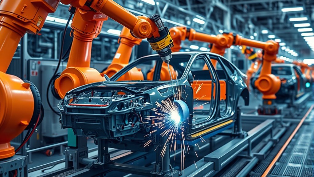
Body-in-white lines locate stamped panels in large fixtures, then use spot-weld robots to create the planned joining pattern. Other stations may add laser seams, brazed roof joints, studs, adhesives, rivets, or clinched joints. Dimensional checks confirm that the body remains within assembly limits before paint and final assembly.
Frame and underbody cells commonly use robotic arc welding on rails, crossmembers, mounts, subframes, and brackets. Positioners rotate the assembly to improve torch access and help keep welds in favorable positions. Joint design and the approved weld procedure determine fillet-weld size, penetration, sequence, and heat input; plate thickness alone does not set a universal maximum fillet size.
Surface condition matters. Oil, scale, oxide, coatings, moisture, and inconsistent gaps can change arc stability, porosity risk, resistance, and fusion. Proper cleaning must match the base metal and coating requirements without removing needed corrosion protection.
- Load and verify the part set.
- Clamp the assembly to the approved datum scheme.
- Run spot, arc, laser, stud, or mixed joining operations in the planned sequence.
- Monitor selected signals and tool condition.
- Inspect critical dimensions and weld features.
- Release, repair, or reject the part under the control plan.
How Do Auto Plants Control Robotic Weld Quality?
Quality control starts before the robot moves. Engineers define the joint, material stack, weld procedure, acceptance criteria, inspection method, and reaction plan. Production then has to keep each input inside its validated range.
- Part and fixture control: Check dimensions, gaps, clamp force, locator wear, and part-present sensors.
- Parameter control: Protect approved recipes and record changes to current, voltage, time, force, speed, wire feed, gas, focus, and other critical settings.
- Tool control: Track electrode caps, tip dressing, contact tips, nozzles, liners, cables, cooling, optics, and calibration.
- Process monitoring: Use electrical, mechanical, optical, acoustic, thermal, or vision signals where they have been correlated with accepted welds.
- Inspection: Apply the visual, destructive, nondestructive, leak, fatigue, dimensional, or proof tests required by the control plan.
- Traceability: Store part identity, program version, alarms, inspection results, and repair history when the risk and customer requirements justify it.
Inspection frequency should follow the part’s risk, process capability, customer requirements, and quality plan. A safety-critical joint normally needs stronger controls than a nonstructural bracket.
Pro Tip: Treat the fixture, cables, cooling system, wire feeder, electrodes, torch, and sensors as part of the welding process. Many “robot problems” begin outside the robot arm.
Where Does Robotic Welding Still Need People?
People define, validate, and maintain the process. A robotic cell needs welding knowledge as well as automation knowledge.
- Welding engineers and technicians develop procedures, set acceptance limits, and investigate defects.
- Robot programmers create paths, manage tool frames, avoid collisions, and control changeovers.
- Controls and safety specialists integrate interlocks, safe functions, networks, and recovery logic.
- Tooling teams maintain fixtures, locators, clamps, dress packages, and positioners.
- Maintenance staff service guns, torches, feeders, cooling, extraction, optics, cables, and robots.
- Quality staff inspect welds, review trends, approve repairs, and verify corrective action.
- Operators load parts, watch the process, respond to alarms, and follow approved restart procedures.
Manual welders also remain useful for prototypes, repairs, low-volume options, hard-to-fixture assemblies, and work with too much variation for the installed cell. Training and qualification should match each person’s actual task; a general welding certificate alone does not qualify someone to change a robot safety system or approve an automotive weld procedure.
What Safety Controls Do Robotic Welding Cells Need?
Robot safety must cover motion, stored energy, welding hazards, and the way people enter or recover the cell. The current international references are ISO 10218-1:2025 for industrial robots and ISO 10218-2:2025 for industrial robot applications and robot cells.
- Perform and document a task-based risk assessment for operation, setup, teaching, maintenance, jam clearing, and recovery.
- Use fixed or interlocked guarding, presence sensing, safe controls, and controlled access as required by the risk assessment.
- Apply lockout/tagout or the approved hazardous-energy procedure before servicing when unexpected startup or released energy could cause harm.
- Control arc radiation, laser radiation, sparks, hot parts, fire risk, electrical hazards, compressed gas, hydraulic or pneumatic pressure, and stored mechanical energy.
- Capture fumes near the source and evaluate worker exposure. NIOSH’s welding-fume guidance explains that fume composition and exposure depend on the wire, rod, flux, base metal, and work conditions.
- Provide safe teaching and recovery methods, clear restart rules, emergency stops, training, and routine safeguard tests.
Collaborative operation is not automatic just because a cobot is used. The welding torch, hot workpiece, sharp fixture, fumes, and application speed may still require separation or additional safeguards.
What Challenges Do Robotic Welding Systems Face?
Robotic welding is sensitive to variation. The robot may repeat its path accurately while the joint moves because stamped parts spring back, castings vary, tubes rotate, clamps wear, or heat distorts the assembly.
- Fit-up and tolerance stack: Gaps and part position may exceed what the weld process can bridge.
- Material behavior: Advanced steels, aluminum, coated sheets, dissimilar metals, and copper connections respond differently to heat and current.
- Tool wear: Electrode caps, contact tips, liners, nozzles, cables, optics, and fixtures change during production.
- Programming and changeover: New models need paths, recipes, reach studies, collision checks, validation, and operator training.
- False confidence in data: A process signature can look normal even when a hidden joint condition is wrong.
- Capital and downtime: The cell must repay its integration, tooling, maintenance, training, floor-space, and support costs.
- System integration: Robot, PLC, welder, sensors, safety controls, conveyors, and plant networks must exchange reliable signals.
Mixed-material vehicle design adds another limit: some combinations cannot be fusion welded reliably without special interlayers, coatings, joint geometry, or an alternative joining method. Corrosion protection around dissimilar metals must be part of the design.
What Maintenance and Troubleshooting Do Robotic Weld Cells Need?
Preventive maintenance protects both uptime and weld quality. The schedule should follow the equipment maker’s instructions, production history, and the control plan.
| Symptom | Possible Causes | Checks |
|---|---|---|
| Weld location shifts | Loose fixture, locator wear, wrong tool frame, moved part, collision, calibration drift | Verify datums, clamps, mastering, TCP, program version, and collision history |
| Erratic arc or burnback | Wire-feed restriction, worn contact tip, poor ground, wrong drive-roll pressure, damaged cable | Inspect feeder, liner, tip, rolls, cable path, ground, and recipe |
| Porosity | Contamination, poor shielding, leak, draft, wet material, wrong gas flow | Check surface condition, hoses, flow at the torch, nozzle, gas supply, and airflow |
| Weak or inconsistent spot weld | Worn or misaligned caps, low force, current variation, coating change, poor cooling | Check cap geometry, dressing, force calibration, current, water flow, and sheet stack |
| Frequent nuisance stops | Intermittent sensor, cable damage, utility pressure, network timing, dirty optics | Review alarm history, I/O timing, connectors, air quality and pressure, and sensor condition |
Clean, dry compressed air matters where pneumatic clamps, valves, tip dressers, or cleaning devices depend on it. It is a support-utility issue, not a universal weld variable. Maintenance teams should troubleshoot the complete cell instead of changing weld settings first.
When Does Robotic Welding Make Economic Sense?
Automation usually makes the strongest case when parts repeat, annual volume is stable, weld locations are accessible, fixtures can control variation, and quality or safety benefits have measurable value. High-mix work can still be automated, but it needs flexible tooling, fast programming, recipe control, and a realistic changeover plan.
A business case should include more than robot purchase price:
- Robot, controller, welding package, positioner, fixtures, guarding, extraction, and utilities
- Integration, simulation, programming, risk assessment, validation, and training
- Consumables, spare parts, preventive maintenance, software, and technical support
- Floor space, material flow, upstream part quality, and downstream inspection
- Expected uptime, cycle time, first-pass yield, scrap, rework, and model-change costs
A pilot cell or simulation can expose reach, collision, takt-time, and fit-up problems before a full line is built. The best return comes from a stable process, not from choosing the fastest robot on paper.
What’s Next for Robotic Welding in Cars?
Future systems will use more vision, seam finding, adaptive path control, tool-condition monitoring, and part-level traceability. Better analytics can help teams find drift before it becomes a large batch of rework.
Electric vehicles are expanding laser and precision-joining work on battery enclosures, busbars, cells, power electronics, and motor components. These parts may need low distortion, electrical performance, leak tightness, or very small process windows. Inspection and traceability therefore become as important as robot speed.
| Capability | What It Adds | Important Limit |
|---|---|---|
| Vision and seam finding | Locates joints and checks part position | Needs calibration, clean optics, and a visible feature |
| Adaptive control | Adjusts selected settings within validated limits | Cannot rescue every bad joint or wrong part |
| AI-assisted inspection | Classifies images or process patterns | Needs representative training data and ongoing validation |
| Digital traceability | Links process and inspection data to parts | Data quality and reaction plans must be controlled |
| Offline programming | Reduces line-side teaching and tests reach | The digital model must match the real cell |
Smarter tools will help operators make faster decisions, but they will not remove the need for process engineering. The strongest plants will combine automation data with physical inspection, disciplined maintenance, and workers who understand both welding and robotics.
Frequently Asked Questions
How do robots handle weld quality checks in real time?
The cell records selected signals such as current, voltage, force, resistance, wire feed, seam position, or weld images and compares them with approved limits. It may flag the part, stop the cycle, or make a validated adjustment. Plants still use inspection because a normal process signal does not guarantee joint strength.
Can robotic welding work on mixed-material vehicle assemblies?
Yes, but the process must match the material pair, coating, thickness, heat limit, joint design, corrosion risk, and inspection plan. Some mixed-material joints use laser or specialized welding. Others are better suited to adhesives, rivets, clinching, or flow-drill screws.
What safety measures protect workers near welding robots?
Typical controls include a task-based risk assessment, fixed or interlocked guarding, presence sensing, safe control functions, emergency stops, lockout/tagout, arc or laser shielding, fume extraction, fire prevention, and trained access and recovery procedures.
How long does it take to program a new robot weld path?
A simple path may be taught quickly, but a production-ready change can take much longer. The team must also confirm reach, collision clearance, fixture accuracy, weld settings, safety logic, cycle time, inspection, documentation, and repeatability. Complex assemblies may require offline simulation and several validation runs.
What happens when a robotic weld fails during production?
The reaction plan may stop the cell, flag the part, route it to inspection, or allow an approved repair. Technicians review the part, alarms, process data, tool condition, fixture, material, and program version before changing settings. The part is released only under the plant’s quality rules.
Is MIG welding different from arc welding?
MIG is a type of arc welding. In industry, the broader term MIG/MAG or gas metal arc welding describes a process that feeds a wire electrode through the torch while shielding gas protects the arc and weld pool. TIG is also an arc-welding process, but it uses a nonconsumable tungsten electrode.
Can a robot weld a part without a fixture?
Some vision-guided or positioner-based applications use minimal tooling, but most automotive welds still need controlled part location and fit-up. A robot can adapt to limited variation; it cannot make an unstable or incorrectly assembled joint reliable.
Does robotic welding eliminate manual welders?
No. Robots take over many repetitive production welds, while people handle process development, programming, setup, maintenance, inspection, repair, prototypes, low-volume work, and assemblies that vary too much for the installed tooling.
Conclusion
Robotic welding helps automotive plants make repeated joints at a stable pace, but the robot is only one part of the result. Fixtures must hold the assembly, welding equipment must deliver the approved process, sensors and inspection must detect problems, and trained people must maintain and improve the cell.
The best starting point is the same for spot, arc, and laser welding: control part fit-up, use a validated procedure, maintain the tool, protect workers, and verify the finished joint. When those basics are strong, automation can reduce variation, improve traceability, support safer work, and keep high-volume vehicle production under control.
Sources
- ISO 10218-1:2025 — Industrial robots — current safety requirements for the robot as machinery.
- ISO 10218-2:2025 — Industrial robot applications and robot cells — integration, operation, maintenance, and cell-safety requirements.
- OSHA Technical Manual: Industrial Robot Systems and Robot System Safety — system components, hazards, risk reduction, and applicable standards.
- NIOSH: Welding Fumes and Manganese — welding-fume composition, exposure factors, and health guidance.
- FANUC: Robotic Spot Welding — automotive spot-welding applications, repeatability, throughput, and maintenance monitoring.
- TRUMPF: AI Inspection for Automotive Laser Welding — in-cell weld-image inspection for body and EV components.



