
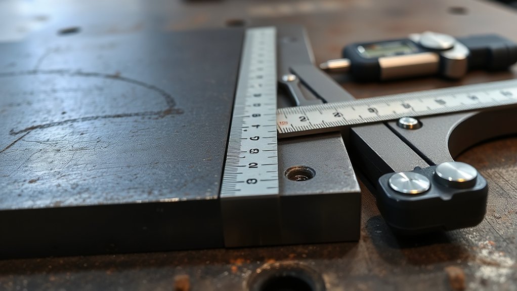
Good welds start before the arc does. Weld joint fit-up controls the root opening, alignment, bevel geometry, contact between parts, and the position of backing or inserts. A gap that looks small can still fall outside the approved joint detail. Check the drawing, project specification, applicable code edition, and Welding Procedure Specification (WPS) before you tack or weld.
Quick Answer
There is no universal maximum weld gap or hi-lo limit. The accepted fit-up comes from the approved joint detail, project specification, governing code, and WPS. Measure root opening, root face, bevel angle, alignment, socket position, and tack condition before welding, then correct any out-of-tolerance joint before heat locks it in place.
Key Takeaways
- Do not treat 1/16 inch, 1/8 inch, or any other shop number as a code-wide limit.
- Confirm the drawing, project specification, code edition, and WPS revision before checking fit-up.
- Measure the full joint, because a short local tight spot or wide spot can matter even when the average gap looks acceptable.
- Use the correct gauge for the joint; a straightedge cannot show internal pipe hi-lo when the inside surface is inaccessible.
- Recheck fit-up after tack welding and before production welding begins.
At a Glance
| Time Required | About 5–20 minutes per joint, depending on size, access, and documentation needs |
| Difficulty | Moderate; code work should be checked by qualified personnel |
| Tools Needed | WPS and drawing, ruler or gap gauges, feeler gauges, bridge-cam or weld gauge, square, bevel gauge, straightedge, and pipe hi-lo gauge when applicable |
| Cost | No added cost when approved gauges are already available; specialty or calibrated tools vary by job |
Warning: Support heavy parts, control pinch points, remove fire hazards, and use the required welding PPE and ventilation. Do not use clamps, wedges, heat, or impact to force a joint into position unless the approved fabrication procedure permits it.
What’s in This Article
- What Is Weld Joint Fit-Up?
- How Big Can a Weld Gap Be?
- How Is Hi-Lo Misalignment Measured?
- What Do the Welding Codes Allow?
- How to Read Weld Joint Fit-Up Limits by Code
- Why Root Opening Affects Weld Quality
- Socket Weld Gap and Insertion Depth
- When Small Gaps Become Weld Defects
- Fit-Up Checks by Weld Type
- How to Control Weld Joint Fit-Up Before Welding
- Frequently Asked Questions
- Conclusion
- Sources
What Is Weld Joint Fit-Up?
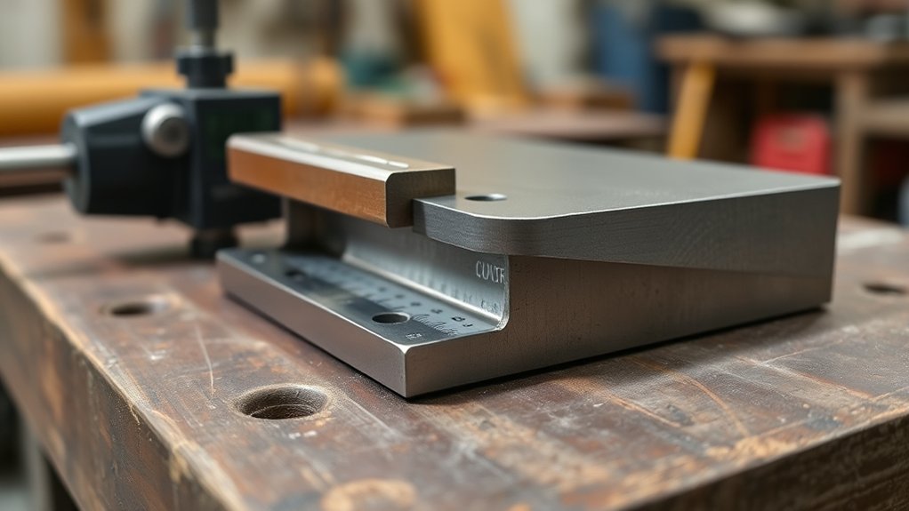
Weld joint fit-up is the condition of the parts immediately before welding. It includes more than the visible space between two edges. A complete check may cover:
- Root opening: the separation at the joint root.
- Root face or land: the unbeveled edge at the root.
- Groove or bevel angle: the prepared angle that gives the electrode or arc access to the joint.
- Mismatch or hi-lo: the offset between adjoining surfaces.
- Angular alignment: whether the parts meet at the required angle.
- Contact and overlap: the faying-surface condition in lap, T-, and fillet-weld joints.
- Backing, inserts, and consumable rings: their type, position, and contact where the joint design uses them.
- Tack welds: their size, spacing, quality, and placement.
- Cleanliness: removal of oil, paint, moisture, scale, coatings, and other contamination as required by the procedure.
Good fit-up supports consistent access to the root and helps the welder keep the arc, electrode, and filler metal where the procedure expects them. It also reduces avoidable variation in penetration, weld profile, distortion, and deposited weld metal.
Fit-up is a preweld inspection. Nondestructive examination after welding may find certain discontinuities, but it does not replace the need to verify the joint before it is covered by weld metal. The National Board’s weld-inspection guidance emphasizes checking joint preparation and using the approved procedure before welding begins.
Note: The WPS is not the only controlling document. The drawing, contract specification, adopted code, engineering instructions, and approved procedure must agree. Stop and request clarification when they conflict.
How Big Can a Weld Gap Be?
A weld gap can be only as large—or as small—as the approved joint permits. There is no single gap that applies to every groove weld, pipe weld, pressure vessel, structural connection, or sheet-metal joint.
You may see nominal root openings around 1/16 to 1/8 inch on some groove-weld details, but that range is an example, not a universal acceptance limit. Other qualified details may use zero root opening, a different opening, backing, a consumable insert, or a process-specific range.
Do not copy a value from another job. A pressure-vessel procedure that uses a comparatively wide opening—such as a nominal 1/4 inch on a specific qualified joint—does not make that opening acceptable for a different vessel, pipe, process, material, or structural detail.
Check both the nominal dimension and its tolerance. A drawing may state a target opening plus or minus an allowed amount. Inspect the entire joint, including starts, stops, corners, tack locations, and areas pulled by clamps.
A familiar shop number is not an acceptance criterion until it appears in the approved documents for that joint.
How Is Hi-Lo Misalignment Measured?
Hi-lo is the offset between adjoining surfaces at a butt joint. The correct measuring method depends on whether you can reach the inside surface and whether the parts are plate, pipe, or tubing.
- Plate or accessible outside surfaces: place a straightedge across the joint and use a feeler gauge, depth gauge, or bridge-cam gauge to measure the step.
- Pipe with access to the bore: use an internal hi-lo gauge or another approved tool that contacts both inside surfaces.
- Pipe without bore access: use the specified external method and confirm that it represents the required internal alignment. Outside diameters, wall thicknesses, ovality, and end preparation can make an external reading misleading.
- Different thicknesses: verify whether the drawing requires a transition, taper, counterbore, or other preparation before judging mismatch.
Take readings around or along the joint rather than at one convenient point. Record the largest out-of-tolerance condition when the quality plan requires traceability. Also check angular misalignment, because two surfaces can have little visible hi-lo while the members still meet at the wrong angle.
A blanket 1/16-inch hi-lo limit is not safe to apply to every structural or piping weld. Use the exact limit and measuring method stated by the approved joint detail, code provision, project specification, or WPS.
What Do the Welding Codes Allow?
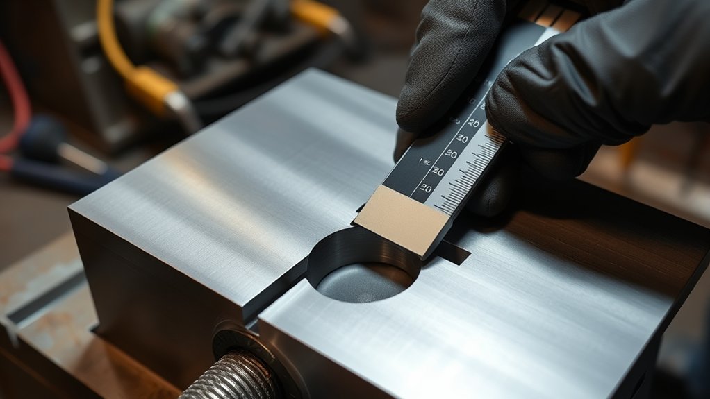
Welding codes have different scopes, joint details, qualification rules, fabrication requirements, and acceptance criteria. They should not be compressed into one generic table of root-gap numbers.
As of July 2026, the current structural-steel code page identifies AWS D1.1/D1.1M:2025-AMD1. The amendment was issued in January 2026. The current ASME B31.3 Process Piping product page lists the 2024 edition. API Standard 1104, 22nd Edition covers welding used in pipeline construction and in-service repair within its stated scope.
Code-Specific Fit-Up Limits
| Standard | Primary scope | What to verify for fit-up |
|---|---|---|
| AWS D1.1/D1.1M | Structural steel within the code’s scope | Applicable prequalified or qualified joint detail, fabrication tolerances, WPS, drawing, and contract requirements |
| ASME B31.3 | Process piping | Joint preparation and assembly rules, engineering design, project specification, qualified procedure, and examination plan |
| API Standard 1104 | Covered pipeline and related-facility welding | Qualified procedure, production joint preparation, alignment method, project specification, and inspection requirements |
WPS-Defined Gap Allowances
A WPS may state the qualified or permitted range for root opening, root face, groove angle, backing, and other joint variables. Read the complete joint-design entry, not just one number. Also verify that the WPS applies to the base-metal group, thickness, diameter, process, position, backing condition, and service involved.
Do not assume the WPS can override the governing code or engineering documents. When the limits disagree, hold the work and obtain direction from the responsible welding engineer, inspector, or authorized representative.
How to Read Weld Joint Fit-Up Limits by Code
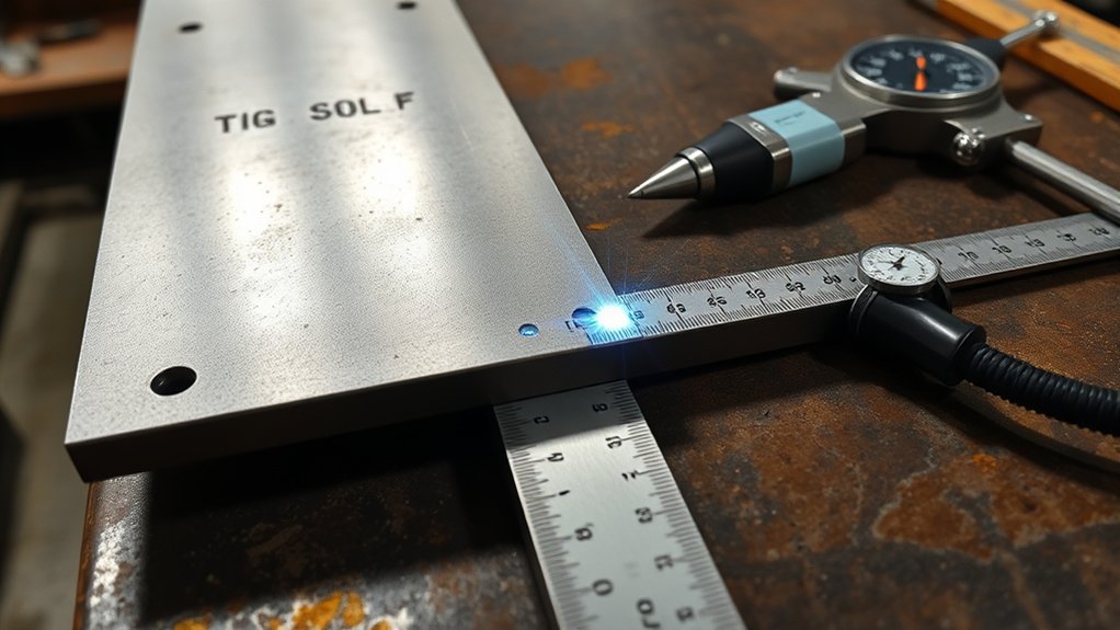
Use a document-based process instead of searching for one universal tolerance:
- Identify the application. Structural steel, process piping, pressure equipment, and transmission pipelines may fall under different standards.
- Confirm the adopted edition. A project may legally or contractually use an earlier edition even when a newer edition is available.
- Find the joint detail. Check the drawing, weld symbol, standard joint designation, backing, groove angle, root face, and nominal root opening.
- Read the WPS range. Confirm that the procedure matches the joint and materials being welded.
- Check project tolerances. Contract documents may be more restrictive than a general code allowance.
- Confirm the inspection point. Know who must accept the fit-up and whether measurements need to be recorded before tacking, after tacking, or immediately before welding.
This approach avoids a common error: treating a nominal joint dimension as though it were the full acceptance rule. The tolerance, measurement location, local variation, taper requirements, and approved repair method may be just as important as the nominal gap.
Why Root Opening Affects Weld Quality
The root opening changes arc access, puddle support, filler-metal demand, and the welder’s ability to fuse both sides of the root. Its effect depends on the process, electrode size, backing, root face, groove angle, material thickness, position, and heat input.
- Too narrow for the approved detail: can restrict access and increase the risk of incomplete root penetration or fusion.
- Too wide for the approved detail: can increase burn-through risk, root reinforcement, filler-metal use, distortion, and difficulty controlling the puddle.
- Uneven opening: forces the welder to change travel speed, manipulation, or deposition within the same joint.
- Correct and uniform fit-up: gives the welder a repeatable joint that matches the qualified procedure.
Porosity and incomplete fusion have many possible causes, so do not blame every discontinuity on gap size alone. Contamination, shielding, technique, parameters, and access also matter.
Socket Weld Gap and Insertion Depth
Socket-weld fit-up is controlled by the fitting dimensions, pipe engagement, alignment, cleanliness, and the assembly method required by the piping code and project procedure. ASME B16.11 covers dimensions, tolerances, ratings, marking, and material requirements for forged socket-welding and threaded fittings.
Many piping procedures require the pipe to be fully inserted and then withdrawn slightly—often about 1/16 inch (1.5 mm)—before welding. Treat that as a procedure-dependent assembly step, not a universal free gap for every socket joint. The adopted piping code, fitting type, engineering specification, and WPS control.
Do not use a generic “minimum 1/4-inch insertion” rule. The correct engagement depends on the actual socket dimensions and applicable requirements. Marking the pipe at the socket face before withdrawal can help the inspector confirm that the pipe was inserted and positioned as required.
Warning: Do not deliberately bottom the pipe and leave it there when the approved procedure requires withdrawal. Do not create an excessive withdrawal gap in an attempt to “make room” for expansion.
When Small Gaps Become Weld Defects
A fit-up condition is not automatically a weld defect, because the weld has not yet been made. It becomes a fit-up nonconformance when it falls outside the approved requirement. If welding continues, that condition may contribute to a rejectable weld or dimensional problem.
Stop and obtain approval when you find:
- a local root opening, root face, bevel angle, or mismatch outside the allowed range;
- joint faces pulled together only by heavy force or temporary restraint;
- damaged, contaminated, laminated, cracked, or poorly cut edges;
- tacks with cracks, porosity, slag, lack of fusion, or an unapproved size or location;
- backing, inserts, or purge dams installed incorrectly;
- a change in wall thickness or diameter that creates unexpected internal mismatch;
- preheat, interpass-control, or environmental conditions that do not meet the procedure.
NDE after welding should not be used as permission to weld over known bad fit-up. Correct the joint first or use a documented disposition approved by the responsible authority.
Fit-Up Checks by Weld Type
Different joints require different checks. The table below identifies the variables to inspect without inventing one gap for every application.
| Weld or joint type | Main fit-up checks | Common concern |
|---|---|---|
| Open-root groove weld | Root opening, root face, groove angle, mismatch, tack quality, backing or purge requirements | Uneven gap changes puddle control and root penetration |
| Backed groove weld | Backing type, contact, continuity, root opening, alignment, and access | Poor backing contact or wrong backing material |
| Pipe butt weld | Internal hi-lo, root opening, land, bevel, ovality, diameter and wall-thickness transition | External alignment can hide internal mismatch |
| Fillet, lap, or T-joint | Contact between faying surfaces, overlap, angle, root condition, weld access, and member position | Gaps may require a changed weld size or engineering disposition |
| Socket weld | Insertion, required withdrawal, alignment, cleanliness, socket dimensions, and fillet-weld placement | Bottoming or excessive withdrawal |
| Thin sheet or autogenous TIG joint | Edge match, uniform contact or specified micro-gap, cleanliness, fixture support, and distortion control | Small changes can cause burn-through or edge mismatch |
Products Worth Considering

PASS X-RAY INSPECTIONS WITH CONFIDENCE: Designed to cut radiographic rejects by accurately measuring internal misalignment after fit-up. Delivering professional-grade precision up to ±0.001 inches, this gauge is NBS calibration capable, making it the trusted choice for Certified Welding Inspectors (CWI) and serious pipefitters.

[Measure Internal Misalignment]: This is a Hi Lo gauge for measuring size of welding,and it can measure internal misalignment (Range: 0-5/32" )and fit-up gap ( Range:0-3/16" ) in Standard Reading Only

[Precision Measurement]: Designed for internal alignment and fit-up/misalignment, it can measure internal misalignment (Range: 0-5/32") and fit-up gap (Range:0-3/16") in Standard Reading Only.
How to Control Weld Joint Fit-Up Before Welding
Products Worth Considering

Angle of Preparation, 0° to 60° and Excess Weld Metal (capping size)

Compatible with CGA-580 tanks: Easily attach this Gas Pressure Regulator/Flowmeter to your Argon, Helium, and CO2 tanks with its CGA-580 inlet connector
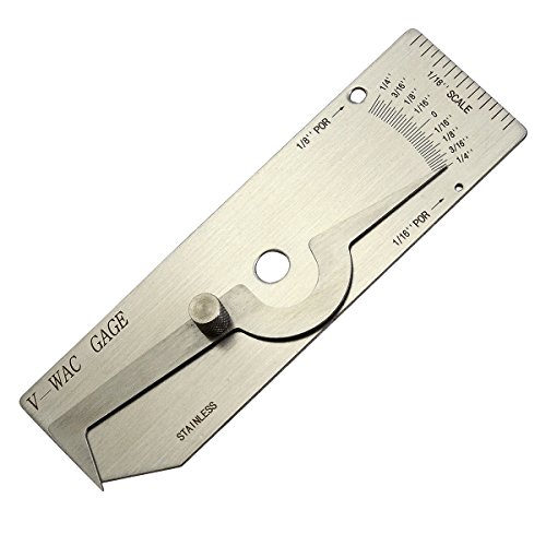
V-WAC Single Weld Gage
1. Verify the Job Documents
Confirm the drawing revision, weld symbol, material identification, governing code edition, WPS number and revision, and any inspection hold point. Make sure the joint you see matches the joint the procedure covers.
2. Inspect the Prepared Edges
Check cut quality, bevel angle, root face, edge damage, laminations, coatings, moisture, oil, and grinding marks. Measure rather than judging by eye. A simple filler-wire or rod gauge may provide a quick comparison, but use calibrated or approved tools when the quality system requires them.
3. Assemble Without Harmful Force
Use approved fixtures, dogs, clamps, strongbacks, or internal alignment tools. Support the parts so they cannot drop, roll, or pinch workers. Do not hide spring-loaded misalignment with temporary force that will release during welding or after the restraint is removed.
4. Measure the Complete Joint
Check root opening, mismatch, angle, offset, socket position, backing, and dimensional alignment at enough points to find local variation. For circular joints, measure around the circumference. For long seams, check both ends, tack locations, corners, and intermediate points.
5. Make and Inspect Tack Welds
Use qualified welders, approved consumables, required preheat, and the procedure specified for tacks that remain in the weld. Remove cracked or defective tacks by an approved method. Feather tack ends when the procedure requires it so the production weld can tie in smoothly.
6. Recheck After Tacking
Tack shrinkage can change the opening and angular alignment. Recheck the same variables before production welding. Record the measurements and inspector acceptance when the inspection and test plan requires proof.
7. Correct Out-of-Tolerance Fit-Up
Use an approved correction method, such as re-beveling, trimming, realigning, replacing a damaged part, adjusting a fixture, or obtaining an engineered repair or disposition. Do not bridge an oversized gap with random scrap, excessive weld metal, or an unapproved buildup.
Pro Tip: Mark the target and tolerance on a traveler or fit-up sheet, then use go/no-go gauges where practical. This reduces arithmetic errors and makes repeat inspections faster.
Follow applicable hot-work controls before striking the arc. OSHA’s general welding requirements address ventilation and other welding hazards. The fit-up inspection does not replace fire prevention, PPE, fume control, electrical safety, or confined-space requirements.
Frequently Asked Questions
Which standard applies to weld fit-up and tolerances?
It depends on the application and contract. Structural steel may use AWS D1.1, process piping may use ASME B31.3, and covered pipeline work may use API Standard 1104. Confirm the adopted edition, drawing, project specification, joint detail, and WPS before accepting the fit-up.
What is the fit-up tolerance for AWS D1.1?
AWS D1.1 does not have one root-gap or hi-lo number for every weld. The allowed dimensions depend on the applicable prequalified or qualified joint detail, WPS, fabrication requirements, drawing, and contract specification. Use the edition adopted by the project.
How big should a weld gap be?
Use the nominal root opening and tolerance shown in the approved joint detail and WPS. Some groove-weld details use openings around 1/16 to 1/8 inch, while others use zero gap or different values. The process, backing, root face, thickness, position, and material all matter.
What is the Rule of 33 in TIG welding?
The Rule of 33 is a pulse-TIG starting point, not a fit-up rule. It commonly means about 33 pulses per second, 33% background current, and 33% peak-time or duty-cycle setting. Machine controls differ, and the settings do not replace a qualified procedure.
What tool should you use to check hi-lo?
Use a straightedge and feeler gauge or a bridge-cam-style gauge for accessible surface mismatch. Use an internal hi-lo gauge for pipe when the bore is accessible. Follow the project’s approved method when internal alignment cannot be measured directly.
Can you weld across an oversized root gap?
Not without an approved basis. Stop the work and use the correction or disposition allowed by the code, engineering documents, and WPS. Adding scrap, excessive filler, or unqualified buildup can create a nonconforming joint.
Do tack welds have to follow the WPS?
Tacks that remain in the completed weld generally need the required welder qualification, consumable, preheat, and quality controls for the work. Defective tacks must be removed or repaired by an approved method. Follow the governing code and project procedure for temporary tacks.
Conclusion
You should treat weld joint fit-up as a controlled part of weld quality, not a minor shop detail. Root opening, bevel geometry, mismatch, backing, tacks, cleanliness, and alignment can affect penetration, distortion, weld profile, and compliance.
Before welding, check the drawing, project specification, governing code edition, and WPS. Measure the complete joint, correct nonconforming conditions through an approved method, recheck after tacking, and document acceptance when the quality plan requires it.
Sources
- American Welding Society — AWS D1.1/D1.1M:2025-AMD1 — current structural-steel code edition, scope, qualification, fabrication, and inspection context
- ASME — B31.3 Process Piping — current edition and process-piping scope
- American Petroleum Institute — API Standard 1104, 22nd Edition — pipeline welding and in-service repair scope
- ASME — B16.11 Forged Fittings, Socket-Welding and Threaded — socket-fitting dimensions, tolerances, ratings, marking, and materials
- OSHA — 29 CFR 1910.252 — welding safety and ventilation requirements
- National Board — Basic Weld Inspection, Part 1 — practical preweld joint-preparation and root-gap inspection guidance




