

To read a weld inspection report, start by matching the report to the job drawings, weld ID, WPS, inspection method, and acceptance standard. Then review the findings, defect notes, measurements, photos, final disposition, and any required corrective action. A good report should show what was inspected, how it was inspected, what was found, and whether the weld meets the required code or needs repair.
Quick Answer
Read a weld inspection report by checking the weld identification, drawing or WPS reference, inspection method, acceptance criteria, recorded indications, measurements, photos, final status, and required repairs. Do not treat a finding as accepted or rejected until you compare it with the governing code, project specification, and inspector’s disposition.
Key Takeaways
- A weld inspection report is only useful when you can trace it to the exact weld, drawing, WPS, inspection date, inspector, and acceptance standard.
- Visual testing mainly finds surface and fit-up issues, while methods such as ultrasonic testing or radiographic testing may be used to evaluate internal flaws.
- An “indication” is not always a rejectable defect. The report must compare the finding with the project’s acceptance criteria.
- If the report lists nonconformance, look for the corrective action, repair method, reinspection result, and final sign-off.
At a Glance
| Time Required | 10 to 30 minutes for a basic report; longer if you must compare code clauses, drawings, photos, or repair records. |
| Difficulty | Moderate. You need basic welding terms plus the correct acceptance standard for the job. |
| Tools Needed | Inspection report, drawings, WPS/PQR, applicable code or project specification, weld map, photos, and any repair or reinspection records. |
| Cost | Reviewing an existing report costs nothing; reinspection, engineering review, or additional NDT may add project-specific costs. |
Warning: A weld inspection report can affect structural safety, pressure containment, code compliance, and job acceptance. Use this guide to understand the report, but rely on the project specification, engineer of record, owner requirements, and qualified welding inspector for final acceptance decisions. On active job sites, follow all hot-work, PPE, fire-watch, and confined-space rules.
Understanding the Purpose of a Weld Inspection Report

A weld inspection report documents the condition of one or more welds at a specific point in the project. It helps prove traceability, supports quality control, and shows whether a weld meets the required acceptance criteria. A complete report should connect the inspection result to the exact weld location, drawing, joint type, welding process, inspection method, inspector, and code or specification used for acceptance.
The report may cover visual inspection, dimensional checks, photographs, repair notes, or non-destructive testing. Depending on the job, the inspection may be performed before welding, during welding, after welding, or after a repair. For example, a pre-weld review may confirm fit-up, joint preparation, material condition, and whether coatings such as paint, oil, rust, or zinc have been addressed before welding. If galvanized material is involved, proper preparation matters because welding over zinc can create quality and safety problems. You can review related preparation guidance in this article on removing zinc coating before welding.
The purpose is not just to “pass” or “fail” a weld. The report should make the inspection decision clear enough that a supervisor, welder, quality manager, engineer, or owner can see what happened and what needs to happen next.
Before You Start: Match the Report to the Job Documents
Before reading the findings, confirm that you are looking at the right report for the right weld. Many mistakes happen when a report is separated from the weld map, drawing revision, or WPS used on the job.
- Weld ID or joint number: Match the report to the weld map, drawing, spool number, beam mark, pipe number, or assembly number.
- Drawing and revision: Confirm that the report references the same drawing revision used for fabrication or installation.
- WPS and PQR: Check whether the listed welding procedure matches the process, base metal, filler metal, position, thickness range, and joint design.
- Inspection date and stage: Note whether the inspection was pre-weld, in-process, final, after repair, or after post-weld heat treatment.
- Acceptance standard: Look for the governing code, project specification, owner requirement, or contract document. The exact edition matters.
- Inspector information: Look for the inspector name, signature, company, certification level, and NDT method qualification when applicable.
Note: A weld can look acceptable in a photo but still fail the project criteria because of size, length, location, internal indications, missing documentation, or an unqualified procedure. Always read the finding against the acceptance standard named in the report.
Key Components of a Weld Inspection Report
A strong weld inspection report gives a clear trail from job requirements to inspection results. Use the sections below as your checklist when reviewing one.
Report Identification and Traceability
Start with the header information. It should identify the project, client, report number, inspection date, location, drawing number, revision, and weld or component ID. If any of these are missing, the report may be hard to defend during audit, turnover, or later repair work.
Weld Details and Welding Process
Next, check the weld description. This may include the joint type, weld type, process, base metal, filler metal, thickness, diameter, position, and WPS number. Processes may be listed by common names, such as MIG, TIG, stick, or flux-cored welding, or by technical abbreviations such as GMAW, GTAW, SMAW, and FCAW.
Inspection Method and Acceptance Criteria
The report should state how the weld was inspected. Visual testing may check surface profile, weld size, undercut, overlap, cracks, and workmanship. NDT methods may be used when the job requires more than surface inspection. Common methods include penetrant testing, magnetic particle testing, ultrasonic testing, and radiographic testing.
The acceptance criteria are just as important as the method. A report that says “porosity observed” is incomplete unless it also explains whether the porosity is acceptable under the applicable code, project specification, or acceptance level.
Measurements, Findings, and Disposition
Look for actual measurements, not just general comments. Weld size, length, reinforcement, undercut depth, indication length, location, density, and repair area should be recorded when relevant. The final disposition may be listed as accepted, rejected, repair required, hold, retest required, or accepted after repair.
| Report Field | What to Check |
|---|---|
| Weld ID | Matches the weld map, drawing, component, or spool number. |
| WPS / Procedure | Correct process, material, thickness range, position, filler, preheat, and essential variables. |
| Inspection Method | VT, PT, MT, UT, RT, or other method required by the job documents. |
| Findings | Clear notes, dimensions, photos, sketches, indication location, and severity. |
| Disposition | Accepted, rejected, repair required, retest required, or accepted after repair. |
How to Read a Weld Inspection Report Step by Step
- Confirm the report belongs to the weld you are reviewing. Match the weld ID, drawing number, revision, and location before reading the result.
- Check the inspection scope. Make sure the report says whether the inspection covered one weld, a sample group, a repair area, or all welds in a lot.
- Find the acceptance standard. Look for the code, specification, contract requirement, or owner acceptance criteria. Do not assume every job uses the same limits.
- Review the inspection method. Identify whether the result came from visual inspection, dimensional checks, PT, MT, UT, RT, or another method.
- Read the findings carefully. Note the type, size, location, orientation, and number of indications or defects.
- Compare the finding with the acceptance criteria. An indication becomes a rejectable defect only when it exceeds the allowed limit or violates the project requirements.
- Check the final disposition. Look for accepted, rejected, repair required, retest required, or hold for engineering review.
- Verify corrective action. If a repair was required, the report should show the repair method, repair date, reinspection method, and final sign-off.
Pro Tip: Do not stop at the word “acceptable.” Check who accepted it, what standard was used, and whether the report covers the exact weld and repair cycle you are reviewing.
How to Interpret Visual and Non-Destructive Testing Results
Visual inspection and NDT results should be read in context. The report should identify the method used, the area inspected, the equipment or calibration information when required, and the acceptance criteria. NDT is designed to inspect materials or components without damaging them, but each method has limits.
| Method | What It Usually Helps Find | Important Limit |
|---|---|---|
| VT / Visual Testing | Surface cracks, profile, size, undercut, overlap, spatter, fit-up, and workmanship. | Does not prove the weld is free of internal flaws. |
| PT / Liquid Penetrant Testing | Surface-breaking cracks, porosity, seams, and leaks on suitable nonporous materials. | Only finds flaws open to the surface. |
| MT / Magnetic Particle Testing | Surface and near-surface discontinuities in ferromagnetic materials. | Not used on nonmagnetic metals such as aluminum or austenitic stainless steel. |
| UT / Ultrasonic Testing | Internal flaws, lack of fusion, laminations, cracks, and thickness-related issues. | Results depend on operator skill, calibration, geometry, access, and material condition. |
| RT / Radiographic Testing | Volumetric flaws such as porosity, slag inclusions, and some internal discontinuities. | Requires radiation controls and may be less effective for some planar flaws depending on orientation. |
When you see a note such as “linear indication,” “rounded indication,” “lack of fusion,” or “porosity cluster,” do not guess the result. Find the size and location, then compare it with the acceptance criteria. If the report gives only a vague comment without dimensions or disposition, ask for clarification before approving the weld.
Products Worth Considering

Easy-to-use pouch provides industry leading presumptive testing results.

Standard grade kit

DIY Asbestos Sample Test Kit
Identifying Common Weld Defects and Anomalies

A report may use the words indication, discontinuity, defect, or nonconformance. These terms are related, but they are not always the same. An indication is a response found during inspection. A discontinuity is an interruption in the expected material or weld structure. A defect is a discontinuity that fails the acceptance criteria. A nonconformance means the weld, procedure, documentation, or inspection result does not meet a requirement.
| Finding | What It Means | What to Check Next |
|---|---|---|
| Crack | A fracture-like separation in the weld, heat-affected zone, or base metal. | Location, length, orientation, repair procedure, and whether engineering review is required. |
| Porosity | Gas pockets or voids in the weld metal. | Size, spacing, cluster pattern, process gas, cleanliness, and acceptance limits. |
| Slag Inclusion | Nonmetallic material trapped in the weld, often related to cleaning or technique. | Length, depth, location, process used, and interpass cleaning records. |
| Lack of Fusion | The weld metal did not properly fuse with the base metal or previous weld pass. | UT/RT result, joint prep, heat input, travel speed, and repair instructions. |
| Incomplete Penetration | The weld did not reach the required root depth or fusion at the joint root. | Joint design, root opening, backing, welding position, and code limits. |
| Undercut | A groove melted into the base metal along the weld toe and not filled with weld metal. | Depth, length, location, weld size, and whether repair grinding or rewelding is allowed. |
| Burn-Through | Excessive heat or poor support creates a hole or excessive root melt-through. | Material thickness, amperage, root gap, backing, repair limits, and reinspection method. |
| Oversize or Undersize Weld | The weld dimension does not match the drawing, symbol, or code requirement. | Weld gauge reading, drawing callout, fillet size, effective throat, and length. |
Many defects can be reduced by better joint preparation, controlled travel speed, correct heat input, proper shielding, and clean metal. If you are dealing with flux-cored welding, review these flux-core welding tips for practical setup and cleaning habits.
Products Worth Considering
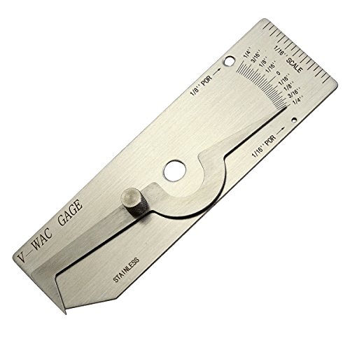
V-WAC Single Weld Gage

Durable: Made of high-quality 304 stainless steel, this gauge set has great rust resistance and wear resistance.

【7 pieces Weld Fillet Gauges】: 7 pieces weld fillet gauges are held by bolt and nut that can be disassembled, each weld gauge can be used to check the size of fillet legs and fillet throats
How to Evaluate Compliance With Industry Standards
To evaluate compliance, first identify the exact standard, specification, or contract requirement used for acceptance. A structural steel job may reference AWS D1.1. A pressure-related job may involve ASME construction-code requirements, and procedure or welder qualification may reference ASME BPVC Section IX. Some international or fabrication projects may reference ISO quality levels or customer-specific criteria.
Do not treat these codes as interchangeable. Each code has its own scope, terminology, acceptance limits, and documentation requirements. The report should show the exact edition or project document that controlled the inspection.
The most important question is not “Does the weld look good?” It is “Does this exact weld meet the acceptance criteria named for this exact job?”
- Confirm that the report lists the correct governing code, standard, drawing, or project specification.
- Check whether the inspection method required by the project was actually performed.
- Verify that any NDT equipment calibration, procedure, and personnel qualification requirements are documented when applicable.
- Compare every recorded indication with the acceptance criteria, not with personal opinion.
- Check whether repair, reinspection, and final acceptance are clearly documented.
- Make sure weld size and geometry match the drawing. For fillet welds, this may include leg size, length, contour, and effective throat. For more detail, review this guide to maximum fillet weld size for plate thickness.
Common Terms and Abbreviations in Weld Inspection Reports
Inspection reports often use short codes and abbreviations. Use this section to decode the most common ones.
- VT: Visual testing or visual inspection.
- PT: Liquid penetrant testing.
- MT: Magnetic particle testing.
- UT: Ultrasonic testing.
- RT: Radiographic testing.
- WPS: Welding Procedure Specification, the written procedure used to make the weld.
- PQR: Procedure Qualification Record, the record used to support or qualify the WPS.
- CWI: Certified Welding Inspector.
- NCR: Nonconformance report.
- CJP: Complete joint penetration.
- PJP: Partial joint penetration.
- 1G, 2G, 3G, 4G: Groove welding positions. 1G is flat, 2G is horizontal, 3G is vertical, and 4G is overhead.
- Field weld: A weld made at the job site rather than in the shop. Field welds may have added fit-up, access, weather, and documentation concerns.
Next Steps After Your Weld Inspection Report
Once you receive the report, review the final disposition first, then work backward through the findings. If the weld is accepted, file the report with the turnover package, quality records, or job documentation. If the weld is rejected or marked repair required, do not proceed as if the weld is complete.
For a rejected or repair-required weld, confirm the reason for rejection, the repair method, who is authorized to approve the repair, and what reinspection is required. Some repairs may need a written repair procedure, additional NDT, engineering review, or owner approval before the weld can be accepted.
After repair, the final documentation should show:
- the original finding and location;
- the repair method used;
- the welder or crew that performed the repair;
- the date of repair;
- the reinspection method and result;
- the final acceptance signature or disposition.
If any part of that trail is missing, ask for a corrected report or supporting documentation. Clear records protect the project later if questions come up during commissioning, warranty work, maintenance, or failure analysis.
Frequently Asked Questions
How do you read a weld inspection report?
Start with the weld ID, drawing, WPS, inspection method, and acceptance standard. Then review the recorded indications, measurements, photos, final disposition, and any corrective action. A report is not complete unless you can trace the finding to the exact weld and see whether it passed, failed, or requires repair.
What does 1G, 2G, 3G, and 4G mean in welding?
These terms describe groove welding positions. 1G means flat, 2G means horizontal, 3G means vertical, and 4G means overhead. Position matters because it affects welder qualification, technique, access, and how the weld may be inspected.
What does “field weld” mean on an inspection report?
A field weld is made at the job site instead of in a shop. Field welds may involve tighter access, weather exposure, fit-up changes, temporary supports, or different inspection timing. The report should still identify the weld location, procedure, inspection method, and acceptance criteria.
What are the most common welding defects listed in reports?
Common findings include cracks, porosity, slag inclusions, lack of fusion, incomplete penetration, undercut, overlap, burn-through, underfill, and incorrect weld size. Whether a finding is rejectable depends on the governing acceptance criteria.
Is an indication the same as a defect?
No. An indication is something detected during inspection. It becomes a defect only when it fails the acceptance criteria. Always check the size, type, location, and code limit before deciding whether the weld is acceptable.
What should you do if a weld inspection report says “repair required”?
Stop treating the weld as accepted. Confirm the defect location, repair procedure, approval requirements, and reinspection method. After repair, make sure the report or supporting records show the reinspection result and final acceptance.
Conclusion
A weld inspection report




