
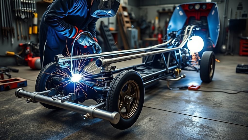
Welding ladder bars is an advanced chassis and suspension job. The welds matter, but the layout matters just as much. You need the vehicle at its intended ride height, the rear axle centered and square, the front crossmember fixed to strong structure, and every rod end free to move before you make final welds. Start with the exact kit instructions, the current rulebook for your class, and a written measurement sheet.
Quick Answer
To weld ladder bars, establish ride height and axle centerline, fixture the front crossmember and housing brackets square, set the driveline angles to the kit and driveshaft maker’s specifications, tack everything, cycle the suspension, then final-weld in short alternating passes. Install the lateral locator and hardware, torque every fastener, and inspect the finished structure before use.
Key Takeaways
- Use the dimensions, materials, welding process, and hardware specified by the ladder-bar kit, chassis plan, and current racing rules.
- Build from a marked chassis centerline and fixed datum points, not from body panels, old holes, or unverified frame edges.
- Set ride height and axle location before checking ladder-bar or driveline angles.
- Tack first, measure again, and control heat so the crossmember and axle housing do not pull out of square.
- A complete installation also needs a suitable lateral locator, shocks or coilovers, travel clearance, correctly installed rod ends, and a post-weld inspection.
At a Glance
| Time Required | Several hours to multiple days, depending on chassis condition, floor or frame reinforcement, axle-bracket work, and inspection requirements |
| Difficulty | Advanced structural chassis fabrication |
| Tools Needed | Correctly sized MIG or TIG welder, stable stands and fixtures, plumb bob, tape measure, digital angle finder, level, clamps, grinder, tube notcher, torque wrench, welding PPE, ventilation, and fire extinguisher |
| Cost | Varies by kit, crossmember, brackets, rod ends, lateral locator, shocks, hardware, reinforcement plates, coating, and professional inspection |
Warning: Ladder bars carry high launch loads and help locate the rear axle. A cracked weld, weak load path, binding rod end, failed lateral locator, or incorrect geometry can cause sudden loss of control. If you are not experienced with structural chassis welding and suspension layout, use a qualified race-chassis fabricator and have the car inspected before road or track use.
Check Rules, Safety, and Kit Specs First
Read the complete ladder-bar kit instructions before cutting the floor, frame, crossmember, or axle brackets. Also check the current rulebook for the sanctioning body and class you plan to run. Chassis requirements can change with vehicle type, construction, weight, elapsed time, and speed. The SFI Foundation lists separate drag-racing chassis specifications for full-bodied cars, dragsters, altereds, funny cars, and roadsters.
Do not copy a tubing diameter, wall thickness, bracket thickness, rod-end size, or mounting dimension from another car. A number that is correct for a roll cage or one ladder-bar kit may be wrong for your crossmember or suspension. Use only the material and dimensions named by the kit maker, chassis designer, and applicable rulebook.
Identify the Material and Welding Procedure
Confirm whether every part is mild steel, 4130 chromoly, cast material, or another alloy before choosing a welding process and filler. Mild-steel brackets and tubing may be suitable for MIG or TIG when the kit permits it. Some chromoly or certified chassis work requires a specific TIG procedure, filler, joint design, and welder qualification.
Do not guess at preheat, interpass temperature, filler wire, or post-weld treatment. Follow the component maker’s procedure. Make sample joints from matching scrap when practical, cut or bend-test them, and correct the machine settings before welding the chassis.
Prepare the Vehicle and Hot-Work Area
Treat the job as hot work. Remove or shield carpet, sound deadener, seam sealer, undercoating, wiring, hoses, brake lines, fuel lines, and other combustibles near the weld area. Follow the vehicle maker’s service instructions for protecting electronics. Disconnect power as directed, and place the welding return clamp on clean metal close to the joint so current does not pass through bearings, rod ends, or sensitive components.
Never weld near fuel vapor or on an uncleaned tank, cell, tube, or enclosed section. Keep suitable fire-extinguishing equipment ready. OSHA requires a fire watch in specified combustible conditions and says that the watch must continue for at least 30 minutes after welding or cutting ends. Use local exhaust or effective ventilation, and keep your head out of the fume plume. Clean paint, solvent residue, plating, oil, and other coatings from the weld zone before heating them.
Note: A disconnected battery does not make the entire vehicle safe to weld. Fuel vapor, hidden seam sealer, wiring on the far side of a panel, and current paths through bearings still need separate controls.
Tools and Materials for Ladder Bar Welding
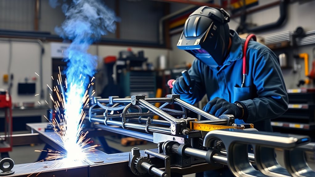
Start with a complete ladder-bar kit or a professionally engineered plan that matches the chassis, vehicle weight, power level, tire, intended use, and racing class. The system normally includes the bars, front crossmember or mounts, axle brackets, rod ends or bushings, spacers, jam nuts, and specified fasteners. It may also require a panhard bar, diagonal link, wishbone, shock mounts, reinforcement plates, and gussets.
Use the tubing, brackets, rod ends, spacers, and fasteners specified for the exact kit and class. Generic chassis dimensions can create weak load paths, poor geometry, or a car that does not pass inspection.
You will need a welder with enough output and duty cycle for the specified material, a tube notcher, grinder, clamps, level, plumb bob, tape measure, digital angle finder, straightedge, squares, torque wrench, and stable stands or fixtures. A paint marker, masking tape, notebook, and labeled measurement diagram make it easier to repeat every check.
Prepare bright, clean metal around each joint. Remove paint, mill scale, rust, oil, plating, and seam sealer far enough from the joint to prevent contamination. Fit tubes and brackets tightly to the joint design. Do not bridge a large gap with weld metal or hide poor fit-up under a gusset.
Products Worth Considering

Universal Fit Design: Weld-on ladder bar rear suspension kit provides strength, stability, and improved traction for custom street rods, hot rods, and race applications.

Safe and Reliable Steel Handles: These playground safety handles are made of excellent quality steel pipe and thick metal plate, more security than plastic, with smooth black powder coated surface, comfortable to touch, sturdy and durable, won't deform and bend, can be used for a long time.

LESS COMPLICATED and easier to set up than a four link
Measure the Chassis Before You Place the Bars
Mark the vehicle centerline before installing the front crossmember or axle brackets. Drop a plumb bob from reliable frame or chassis points and mark the floor with masking tape. Then mark the rear axle centerline, wheelbase points, tire centerlines, driveshaft path, exhaust clearance, brake-line route, shock locations, and the floor areas that may need trimming or reinforcement.
Measure both sides from the same fixed datum points. Do not assume old sheet metal, frame edges, factory holes, or body openings are square. A car may have prior collision damage, chassis twist, uneven body placement, or earlier repairs. Record the measurements before you cut anything.
- Chassis centerline to each frame rail or connector
- Front spindle centerline to rear axle centerline on both sides
- Diagonal measurements between fixed chassis points
- Axle housing end or wheel-mounting surface to chassis centerline
- Planned front-pivot height and side-to-side spacing
- Tire, driveshaft, exhaust, shock, floor, and brake-line clearance
Pro Tip: Label every floor mark and write the matching number on a measurement sheet. Use names such as chassis centerline, axle centerline, left front pivot, right front pivot, and tire centerline so you do not compare the wrong points after tacking.
Support the Car at Ride Height
Place the vehicle on a level work surface and establish its intended ride height with stable stands and fixtures. Represent normal operating weight as closely as practical, including the engine, transmission, rear axle, wheels, tires, fuel load, and driver ballast. Inflate the tires to the intended pressure when the tires are part of the setup.
Do not rely on hydraulic jacks. Support the chassis so it cannot move, and use separate axle or wheel fixtures to hold the rear axle at the planned loaded position. The suspension may need to be unloaded later for travel checks, but the geometry should first be established at ride height.
Measure from the floor to fixed chassis points on both sides. Correct any lean or twist in the setup before locating the crossmember or checking driveline angles.
Position the Crossmember and Support Structure
Position the crossmember where the ladder-bar kit places the front pivots and where the chassis can carry the launch load. It must sit square to the chassis centerline, level side to side, and high enough for safe ground clearance without forcing an incorrect ladder-bar angle.
On a full-frame car, tie the crossmember into sound frame structure as the design requires. On a unibody car, the load often needs to spread through frame connectors, boxed structures, back plates, or other engineered reinforcement. Thin floor sheet metal alone is not a suitable front anchor.
If the chassis plan connects the crossmember to a main hoop or other cage structure, align that structure before final welding. A main-hoop connection is not universal, so do not add or relocate cage tubes without the chassis plan and rulebook.
Crossmember Placement
Set the front pivots so the bars sit at the planned angle when the car is at ride height. Front-pivot height affects the suspension’s instant center, anti-squat behavior, and how quickly load reaches the rear tires. Moving the pivot can change separation, squat, wheel hop, and launch consistency.
Do not use a generic wheelbase fraction as the final location. Use the kit layout, available adjustment holes, tire size, ride height, and chassis designer’s guidance. Confirm clearance to the floor, driveshaft, driveshaft loop, exhaust, brake lines, shocks, tires, and service points through the full travel range.
Main Hoop or Support Alignment
When the approved design uses a main hoop or support tubes as part of the ladder-bar load path, verify that the structure is square to the chassis centerline and matches the chassis plan. Use a level, plumb bob, and equal measurements from fixed datums.
If the support leans or the crossmember twists during tacking, stop and correct it. Do not pull a misaligned structure into place with final welds. Recheck it from the front, rear, and side after every significant tack sequence.
Diagonal Support Braces
Fit any required diagonal braces between the crossmember and the reinforced frame, connector, hoop, or support structure. The tubes should meet the specified nodes with tight fit-up so launch load follows a direct path into strong chassis structure.
- Match the brace locations and material to the chassis plan.
- Keep paired braces equal when the design is symmetrical.
- Back plate or box thin attachment areas as specified.
- Use gussets only where the design calls for them.
- Do not use a gusset to cover a gap, weak tack, or misaligned tube.
Set Ladder-Bar and Driveline Angles
With the chassis and axle fixed at ride height, place a digital angle finder on the transmission output or an approved parallel surface, the driveshaft tube, and the pinion yoke or an approved parallel surface. Record the slope and direction of each component. Pinion angle alone does not describe the complete driveline.
Set ride height before finalizing ladder-bar and driveline angles. Changing chassis height, tire diameter, transmission height, or axle position can change the measured operating angles.
Use the Spicer Driveline Operating Angle Calculator or the driveshaft maker’s method to calculate each U-joint operating angle. Spicer advises that the operating angles should be equal or within 1 degree of each other and notes that 3 degrees or less supports maximum universal-joint life. A performance driveline may have additional limits based on shaft speed, joint series, length, and intended use.
Many rigid-link street and strip cars are initially set with the pinion nose slightly down at rest so it can move toward the target under load. That is not a universal specification. Use the ladder-bar kit, driveshaft maker, chassis builder, and actual loaded measurements to establish the final setting.
Adjust both bars in small, equal steps unless the kit’s setup procedure calls for preload. After every change, recheck axle centerline, wheelbase, bar length, thread engagement, ride height, and all three driveline slopes.
Tack Weld the Brackets in Place
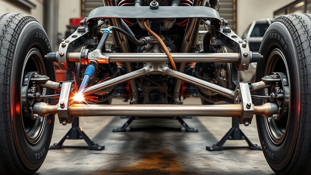
Install the bars with temporary hardware, spacers, and fixtures. Seat every bracket against clean metal without using the bolt to force it sideways. A bolt should pass through aligned holes without loading the rod end or pulling the bracket ears together.
Verify the axle’s fore-aft position, side-to-side position, housing angle, front-pivot spacing, and bar parallelism. Then place small tacks at several points around the brackets and crossmember. Keep the tacks strong enough to hold the layout but easy to remove if a measurement changes.
- Confirm the rear axle is centered to the chassis.
- Check wheelbase on both sides.
- Measure each mount from the chassis centerline.
- Compare matching bar lengths and diagonal measurements.
- Confirm rod-end articulation and bracket spacing.
- Recheck ride height and driveline angles after tacking.
Do not run full beads yet. Tacks let you correct a shifted bracket, twisted crossmember, or housing-angle error before heat locks it into the car.
Square the Ladder Bars Before Final Welding
Measure from each front mount to its matching rear mount, then compare diagonal measurements across the chassis. The ladder bars should sit in the designed planes, with equal side-to-side spacing and no unintended toe, twist, or side load.
Square the axle housing to the chassis datums, not to quarter panels or wheel openings. Body panels can be uneven even when the chassis is straight. Check the wheel-mounting surfaces or verified housing references against the chassis centerline.
Keep the setup at ride height while confirming the primary geometry. Turn each rod end through its expected range by hand. If a joint tightens, reaches its misalignment limit, or drags a bracket, correct the spacing or alignment before welding.
Control Axle-Housing Distortion
Welding suspension brackets to an axle tube can pull the tube, disturb housing-end alignment, damage seals, or create a leak. Use the axle or ladder-bar maker’s fixture and welding sequence. Keep the housing supported, alternate short welds around the assembly, and allow natural cooling between passes.
Do not weld a bracket to a cast center section unless the housing maker or an approved procedure specifically allows it. Cast iron, cast steel, fabricated steel centers, and steel axle tubes require different procedures. When housing alignment is critical, use an alignment bar or have a driveline shop verify the ends after welding.
Warning: Never use a differential bearing, axle bearing, rod end, or installed bolt as the path for welding current. Place the return clamp on the same clean component, close to the weld area.
Weld the Crossmember, Diagonals, Brackets, and Gussets
Remove rod ends, bearings, seals, wiring, hoses, and other heat-sensitive parts when the procedure requires it. Protect threads and machined surfaces from spatter. Confirm the welding sequence before the first final pass.
Weld the crossmember to the prepared chassis structure using the specified joint design. Complete back plates, boxes, and frame-connector ties as shown in the plan. Weld required diagonal braces into the same load path, then add the specified gussets at high-stress junctions.
Use short, controlled passes and alternate sides to balance heat. Stop between groups of welds to check the centerline, front-pivot spacing, axle angle, and diagonal measurements. Let the assembly cool naturally unless the approved welding procedure says otherwise.
Note: Do not weld on installed rod ends, bearing races, bolts, or locking hardware. Heat can damage liners and seals, while spatter can ruin threads and bearing surfaces.
Crossmember Back Plating
Where the design requires back plating, fit the plate tightly to sound chassis metal and prepare the complete joint area. The plate should spread load into the rail, connector, box, or reinforced structure rather than create a stiff patch ending in weak sheet metal.
- Match plate material and thickness to the approved plan.
- Remove coating from the required weld area on every accessible side.
- Use the specified weld length and joint pattern.
- Connect braces to useful structural nodes.
- Inspect for gaps, undercut, porosity, cold lap, and missed edges.
Main-Hoop or Support Diagonals
If the design includes hoop or support diagonals, keep them straight and tied into the specified nodes. Tight tube fit-up and direct load paths are more useful than oversized weld beads on poorly fitted joints.
Recheck the front mounts after welding each diagonal. A brace can pull the crossmember upward, sideways, or into twist if the heat is concentrated on one side.
Gusset Placement Points
Place gussets only at the high-load junctions named by the kit or chassis plan. Fit them tightly and keep their shape clear of rod-end movement, hardware access, floor panels, and suspension travel.
- Front-pivot bracket to crossmember, where specified
- Crossmember to reinforced frame or connector
- Diagonal brace to approved structural node
- Axle bracket reinforcement, when included in the kit
- Shock or locator mounts, when covered by the suspension design
More gussets are not automatically safer. An oversized or abruptly ended gusset can move stress into a weaker area. Follow the engineered design.
Install the Lateral Locator, Shocks, and Travel Controls
Ladder bars mainly control axle rotation and fore-aft movement. Most installations also need a separate lateral locator, such as a panhard bar, diagonal link, or wishbone. Install the type named by the kit and place it so it controls side movement without binding through compression, droop, and body roll.
Install the approved shocks or coilovers, upper and lower mounts, bump stops, and droop limiters. Confirm that the shocks do not bottom internally before the bump stops engage and do not become the unintended droop limit unless the manufacturer designed them for that load.
Check the driveshaft slip travel, U-joint clearance, brake-hose length, tire-to-body clearance, exhaust clearance, and locator clearance at both ends of suspension travel. A ladder-bar assembly can be square at ride height and still bind or hit another part when the axle moves.
Products Worth Considering

[Application] Fit for Chevrolet Suburban 1500 & 2500 2000-2020; for Chevy Tahoe 2000-2020; for Cadillac for Escalade 2000-2020; for Hummer H2 2000-2020
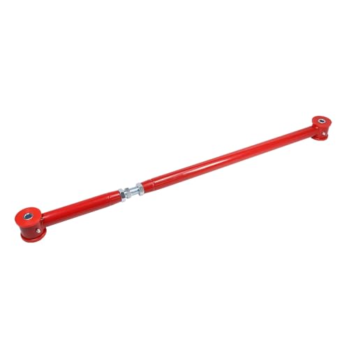
Compatible Vehicles: JDMSPEED Adjustable Rear Panhard Track Bar with polyurethane bushings Compatible with 2000-2020 Chevy Suburban 1500/2500, compatible with 2000-2020 Chevy Tahoe, compatible with 2000-2020 Chevy Avalanche, compatible with 2000-2020 GMC Yukon, compatible with 2000-2020 Cadillac Escalade, compatible with 2000-2020 Hummer H2.

Fitment:for 2005 2006 2007 2008 2009 2010 2011 2012 2013 2014 Ford Mustang 2-Door;BST BSSP track bar is Single adjustable after installation and comes with maintenance free thermofuse bushing;
Install Rod Ends and Final Hardware
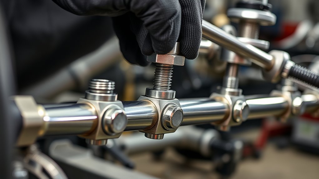
Thread each rod end into the ladder bar in the correct direction and to at least the minimum engagement specified by the rod-end or kit maker. Keep left-hand and right-hand adjusters identified. Do not lengthen a bar until too few threads remain engaged.
Use the specified spacers or misalignment spacers so the rod end is centered in the bracket and can articulate without side-loading. Brackets should support the joint in the intended single- or double-shear arrangement. Add safety washers only when the joint maker or kit design calls for them.
Install the supplied or specified fasteners, nuts, and locking method. Do not replace them with a generic “equivalent” based only on diameter. Grip length, unthreaded shank position, material, finish, thread pitch, nut type, and installation torque all affect the joint.
Tighten every fastener to the kit or hardware maker’s torque specification with a calibrated torque wrench. Apply anti-seize, oil, or threadlocker only when the instructions call for it. Lubrication changes thread friction and can change clamp load at the same torque.
Set the final bar length and any approved preload, then hold the adjuster while tightening the jam nuts. Mark each critical nut and bolt with torque stripe paint so later movement is easier to see.
Check Alignment and Full Suspension Travel
Confirm that the bars, brackets, and lateral locator match the chassis plan. Measure both bar lengths, front-pivot spacing, axle position, wheelbase, housing angle, and distance from the wheel-mounting surfaces to the chassis centerline.
Cycle the rear suspension through full compression and full droop with the springs removed or safely unloaded when practical. Move one side at a time as well as both sides together so you can detect roll bind. Watch every rod end and locator joint while the axle moves.
- No rod end reaches its angular limit.
- No bracket pinches a spacer or joint.
- The axle does not walk sideways beyond the designed amount.
- The driveshaft retains safe slip and U-joint clearance.
- Brake hoses, wiring, and vent lines remain free.
- Tires clear the body, ladder bars, shocks, and locator.
- Shocks and bump stops control travel in the intended order.
Return the car to ride height and measure the driveline angles again. Record the final values, hardware torque, rod-end exposure, shock settings, tire pressure, and ride-height datums.
Inspect Welds and Recheck the Setup
Inspect every accessible weld under good lighting. Look for consistent tie-in, the required weld size, complete edges, and no visible cracks, porosity, undercut, cold lap, missed sections, or burn-through. Check the opposite side of panels for heat damage and hidden fire.
A visual check cannot prove internal weld quality. Use the inspection method required by the sanctioning body, chassis specification, or fabricator. Certified cars may need inspection by an authorized chassis inspector. Correct defects with an approved repair procedure rather than grinding and covering them without identifying the cause.
| Check | What You Want | Why It Matters |
|---|---|---|
| Welds and load paths | Correct joint size, sound tie-in, no visible defects | Reduces the risk of bracket or crossmember failure |
| Geometry | Square, centered, and within the kit tolerances | Supports predictable launches and handling |
| Driveline angles | Within the kit and driveshaft maker’s limits | Reduces vibration and U-joint wear |
| Travel | No bind, contact, hose stretch, or shock overtravel | Keeps the suspension controlled through bump, droop, and roll |
| Hardware | Correct engagement, torque, locking, and torque stripes | Prevents joint movement and loss of adjustment |
Coat and Test the Finished Installation
After inspection and any required nondestructive testing, clean the bare steel and apply a suitable corrosion-resistant coating without covering inspection labels, moving joints, or required identification. Do not coat questionable welds to hide them.
Begin with a static brake, steering, and clearance check. Then make a slow, controlled test away from traffic before any hard launch. Reinspect the welds, brackets, torque stripes, rod ends, shocks, locator, and driveline after the first heat cycle and short test. Recheck them again after the first track session.
Troubleshooting Ladder-Bar Setup Problems
| Problem | Likely Cause | What to Check |
|---|---|---|
| Car pulls left or right on launch | Axle not square, unequal bar length, unapproved preload, tire mismatch, or chassis twist | Centerline datums, wheelbase, diagonals, bar settings, tire pressure, corner weights, and locator position |
| Driveline vibration | Incorrect operating angles, shaft runout, balance problem, worn U-joints, or inadequate slip travel | Transmission, driveshaft, and pinion slopes; U-joints; shaft speed; balance; and slip-yoke position |
| Suspension binds | Side-loaded rod ends, nonparallel brackets, incorrect spacers, or locator conflict | Joint articulation, bracket spacing, panhard or wishbone travel, shocks, bump stops, and roll movement |
| Axle shifts sideways | Loose, damaged, misaligned, or missing lateral locator | Locator mounts, rod ends, bushings, hardware torque, and clearance through full travel |
| Weld or paint cracks near a bracket | Poor fit-up, weak reinforcement, excessive distortion, wrong material procedure, or chassis flex | Stop using the vehicle; inspect the weld, bracket, back plate, gussets, housing alignment, and surrounding structure |
| Rod end loosens or changes adjustment | Loose jam nut, inadequate thread engagement, worn liner, or incorrect locking method | Thread exposure, jam-nut torque, torque stripes, rod-end wear, and kit hardware instructions |
Frequently Asked Questions
What pinion angle should a ladder-bar suspension use?
There is no universal pinion angle. Set the vehicle at ride height, measure the transmission, driveshaft, and pinion slopes, then calculate both U-joint operating angles. Follow the ladder-bar kit, chassis builder, and driveshaft maker. A slight pinion-nose-down static setting is common on some rigid-link cars, but it is only a starting point.
What is the best rear suspension setup for drag racing?
The best setup depends on the chassis, tire, power, vehicle weight, track surface, class rules, and tuning needs. A four-link offers more adjustment. Ladder bars are simpler and can be strong and consistent when the mounts, lateral locator, shocks, and geometry are correctly designed and installed.
Are ladder bars the same as traction bars?
No. Ladder bars are suspension links that locate the rear axle fore and aft and resist axle rotation through front pivots. Traction bars usually work with leaf springs to reduce spring wrap and wheel hop. The parts, geometry, and adjustment methods are different.
How does a ladder-bar suspension work?
Each ladder bar connects the rear axle housing to a forward chassis pivot. Under acceleration, the bars resist housing rotation and transfer load into the chassis. Front-pivot position, bar angle, shock settings, tire behavior, and the car’s center of gravity all influence the launch.
Can I weld ladder bars with a MIG welder?
A properly sized MIG welder may be acceptable for many mild-steel ladder-bar parts when the kit and rules permit it. Some chromoly or certified chassis work requires TIG and a defined procedure. Identify the material first, then use the process, filler, joint preparation, and inspection required by the manufacturer and sanctioning body.
Do ladder bars need a panhard bar, diagonal link, or wishbone?
Most ladder-bar systems need a separate lateral locator because the bars mainly control axle rotation and fore-aft movement. The approved choice may be a panhard bar, diagonal link, or wishbone. Use the device specified for the kit and verify that it does not bind or hit the tires, housing, driveshaft, or chassis through full travel.
Can I weld ladder-bar brackets to any rear axle housing?
No. First identify the axle-tube and center-section materials. Follow the housing or kit maker’s bracket location, joint design, fixturing, and weld sequence. Do not weld to a cast center section without an approved procedure, and verify housing-end alignment after welding when distortion could affect the bearings or axles.
Can ladder bars be used on a street-driven car?
They can be used in some street and strip builds, but the complete design must suit road travel, body roll, ride height, ground clearance, shock travel, driveline movement, and local vehicle laws. A rigid race-only arrangement may bind or ride poorly on uneven streets, so follow the chassis builder’s street-use guidance.
Conclusion
A safe ladder-bar installation follows a repeatable sequence: confirm the design and rules, prepare the hot-work area, establish ride height and chassis datums, fixture the axle and front mounts, set the driveline angles, tack and remeasure, control heat during final welding, then install the lateral locator, shocks, rod ends, and hardware. Cycle the suspension and inspect the complete load path before the car moves under its own power.
Do not tune around a fabrication error. If a bracket cracks, a rod end binds, the axle walks sideways, or the measurements change after welding, stop and correct the cause. A square, reinforced, inspected setup gives the suspension a stable foundation for a safer and more repeatable launch.
Sources
- OSHA 29 CFR 1910.252, General Requirements: fire prevention, fire-watch duration, PPE, ventilation, cleaning-compound, and hot-work precautions.
- OSHA Fact Sheet: Controlling Hazardous Fume and Gases during Welding: coating removal, fume positioning, local exhaust, general ventilation, and respiratory-protection guidance.
- Spicer Measuring Angles Guide: measuring transmission, driveshaft, and axle slopes and comparing U-joint operating angles.
- Spicer Driveline Operating Angle Calculator: calculating operating angles for the driveline joints.
- SFI Foundation Drag Racing Chassis Specifications: selecting the applicable chassis specification by vehicle type and performance category.
- NASA Fastener Design Manual: fastener selection, locking methods, thread lubrication, friction, and torque relationships.



