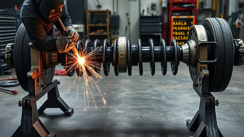
Welding leaf spring perches is a structural suspension job, not a quick bracket repair. You must center and square the axle, match the perch spacing to the spring centerlines, set the pinion angle for the actual driveshaft, and control welding heat. Verify the axle housing and perch materials before you begin, because not every housing uses the same tube, weld procedure, or bracket design.
Quick Answer
To weld leaf spring perches, support the suspension at ride height, measure the spring centerlines, center and square the axle, set the correct driveline operating angles, clean the tube and perches, tack both sides, recheck everything, then complete the specified seams with a balanced welding sequence and natural cooling.
Key Takeaways
- Measure the actual spring centerlines and chassis instead of copying a generic perch-spacing number.
- Identify the axle-tube material and confirm that the housing manufacturer permits bracket welding.
- Calculate U-joint operating angles for your driveline type instead of using a universal pinion-angle target.
- Use clean fit-up, balanced weld sequencing, and only the weld size and seam pattern required for the perch.
- Install suitable new U-bolts when required, torque them to the correct specification, and recheck the complete installation before normal driving.
At a Glance
| Time Required | Several hours for measurement, old-bracket removal, preparation, tacking, welding, cooling, coating, and final checks |
| Difficulty | Advanced; the final welds require structural welding skill and accurate suspension and driveline measurement |
| Tools Needed | Wheel chocks, rated stands or drive-on supports, tape measure, plumb bob, straightedge, angle finder, clamps, grinder, wire brush, non-chlorinated cleaner, suitable welder and consumables, torque wrench, PPE, and fire extinguisher |
| Cost | Varies by perch kit, U-bolts, consumables, coating, axle condition, and whether a professional performs the welding or alignment |
Warning: This is structural suspension work. Do not weld an unidentified or damaged axle housing, and do not attempt the final welds unless you can produce sound structural fillet welds with adequate fusion. Keep fuel, brake, electrical, and rubber parts away from heat and sparks. Follow OSHA hot-work fire-prevention guidance, including suitable fire protection and a fire watch when conditions require one.
Measure Spring Perch Spacing and Pinion Angle
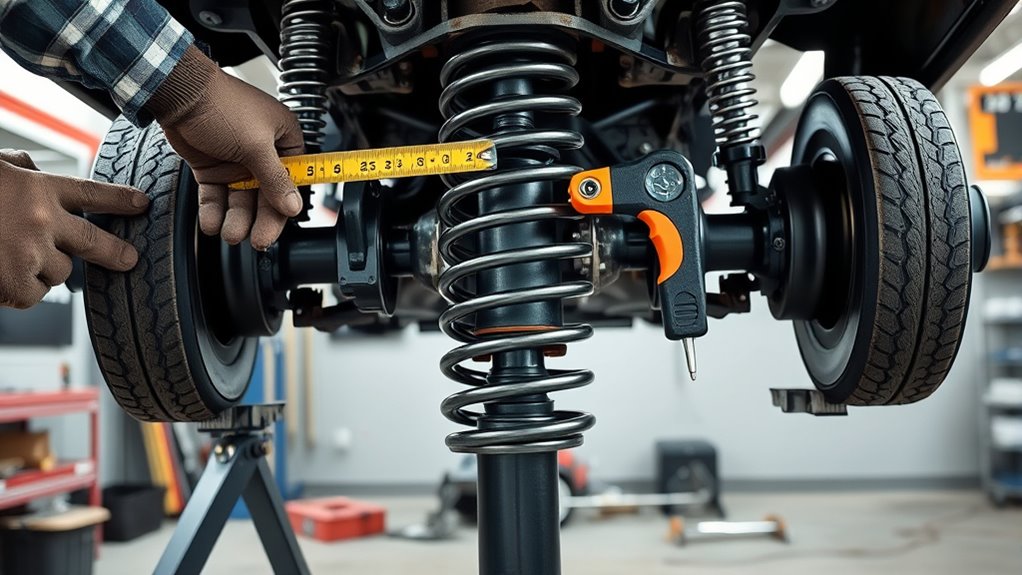
Start by measuring the center-to-center distance between the leaf springs where the axle will sit. Measure from one spring center pin to the other, or copy the original axle only after you confirm that it belonged to the same chassis and spring arrangement. Measure twice from both sides so a bent tape, shifted spring, or off-center center bolt does not mislead you.
Published perch dimensions for classic cars and axle swaps can differ by model year, spring package, and previous modifications. Treat any generic number as a reference only. The vehicle’s actual spring centerlines, verified against reliable service or manufacturer information, control the final perch spacing.
Use a plumb bob, laser, or square from fixed chassis points to locate the axle centerline. Mark the floor, axle tube, and perch positions. Also compare diagonal measurements from the same chassis reference points to the axle ends or brake flanges. Equal side measurements center the axle; equal diagonals help confirm that it sits square to the chassis.
Next, measure the pinion angle with an angle finder. Record the transmission or transfer-case output slope, driveshaft slope, and pinion-yoke slope. Do not copy a fixed “5 degrees up” target. The correct setting depends on the shaft design, vehicle height, suspension movement, driveshaft speed, and manufacturer guidance.
- For a conventional shaft with one single-Cardan U-joint at each end, set the system so the front and rear U-joint operating angles are equal or nearly equal under the intended load.
- For a double-Cardan or CV-style shaft, follow the driveshaft maker’s instructions. The pinion often points more directly toward the shaft, while retaining the small working angle that the joint and bearing require.
- For lifted vehicles, high-torque builds, traction bars, multi-piece shafts, or horizontal driveline offsets, use a driveline specialist or the component manufacturer’s calculation method.
Spicer’s measuring guidance says operating angles at the two ends of a shaft should be equal within 1 degree, and its calculator notes that angles above 3 degrees can reduce U-joint life and cause vibration. Check the manufacturer’s limits for your shaft speed and application rather than treating 3 degrees as permission for every setup.
Note: Measure with the suspension at normal ride height and the vehicle level. Also check the angles at the expected operating load when possible, because spring compression and axle wrap can change the readings.
Verify the Axle Housing Before Welding
Confirm the axle-tube outside diameter, wall condition, and material before selecting the perch or welding procedure. Most weld-on perches attach to steel tubes, but housing construction varies. Do not weld to a cast center section, an unknown alloy tube, a thin or heavily pitted tube, or a heat-treated housing without a procedure approved by the axle manufacturer or a qualified welding professional.
Gather Tools and Set Up Safely
Park on a level, noncombustible surface. Chock the wheels and support the vehicle with equipment rated for the load. To measure at ride height, use drive-on supports or support the axle and spring assembly in a stable way that keeps the vehicle’s weight on the springs. Add secondary stands before working underneath. Never depend on a hydraulic jack alone.
Follow the vehicle service manual’s battery-disconnect and welding precautions. Move flammable materials away and shield the fuel tank, fuel and brake lines, wiring, shocks, bushings, seals, parking-brake cables, and vent hoses. Keep a suitable fire extinguisher within reach, and check hidden cavities where sparks can collect.
Place the welder’s work clamp on clean metal on the axle tube, as close to the weld area as practical. Do not route welding current through wheel bearings, differential bearings, U-joints, or other moving joints. Reposition the clamp when you move to the opposite side of the housing.
Wear a welding helmet with the correct shade, safety glasses, gloves, hearing protection, and flame-resistant clothing. Use ventilation that removes fumes without blowing away shielding gas. OSHA’s welding requirements cover eye protection, protective clothing, ventilation, combustibles, and fire-watch duties.
Warning: Do not use chlorinated brake cleaner or let chlorinated-solvent vapors reach the welding arc. OSHA requires degreasing operations with chlorinated hydrocarbons to stay away from welding atmospheres because arc radiation can create highly toxic gases.
Products Worth Considering
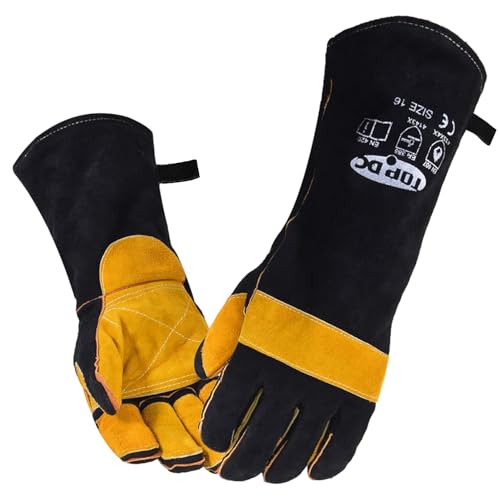
EXTREME HEAT RESISTANT PROTECTION: Reinforced Kevlar stitching, double leather reinforcement and high-strength sewing on the fingers, palms, elbows and backs. An aluminum foil layer in the palm adds insulation. A fully lined interior helps protect against heat, flames, spatter and sparks during welding tasks. Heat resistant up to 932°F (500°C)

✅Arc & Flame Resistant for Life - This 7 oz material is a soft, breathable cotton. They will remain arc and flame retardant regardless of the washes and wear cycles. These cotton fr balaclavas are NFPA 70E Compliant, HRC / CAT 2, EBT = 12 cal/cm² and meet ASTM F1506.

High Quality-100% Heavy Duty Leather Apron with Gloves
Clean and Prep the Axle Housing
With the perch spacing and target angles recorded, clean the axle housing to bare metal. Remove paint, rust, scale, grease, old bracket material, and weld residue from the tube where each perch will sit. The perch saddle must contact the tube evenly without rocking, forced clamping, or a large gap.
Use a compatible non-chlorinated degreaser first and let the surface dry fully. Then use a wire brush, flap disc, or grinder to expose sound metal. Keep grinding dust out of axle vents, seals, brakes, and open housings. For more preparation detail, review this guide on how to clean mild steel for welding.
| Surface | Prep Goal |
|---|---|
| Axle tube | Sound, bare, dry metal with enough clean area for the full required weld |
| Perch saddle | Correct radius, clean edges, and even contact with the tube |
| Old weld areas | Old brackets removed without gouging or thinning the axle tube |
| Grease or oil film | Removed with a compatible non-chlorinated cleaner before welding |
| Moisture and coatings | Eliminated from the weld zone to reduce porosity, fumes, and contamination |
Inspect the axle tube for dents, deep pitting, cracks, bent sections, previous heat damage, or grinder gouges. Check the perch for the correct tube radius, spring width, center-pin hole, and required weld edges. Stop if the tube is damaged or the perch does not fit closely. Welding over poor fit-up can hide a weak joint and lock an alignment problem into the housing.
Products Worth Considering

High performance, contaminant free

Cost-Effective 6 Pcs Angle Grinder Wire Wheel: WENORA Angle grinder brushes are made of high strength hardened carbon steel wire for better performance than comparable products. Wire brush sets for angle grinders are a better value than buying from your local tool store.

4"X5/8"-11 HP.014 CARBNCRIMPWIRECUPBRUSH
Center the Axle Under the Vehicle
Place the axle on the springs at normal ride height, with each spring center pin seated in its perch hole or aligned with the planned locating mark. Use temporary U-bolts or strong clamps only to hold the assembly for measurement. Do not use damaged or undersized hardware as a substitute for the final installation parts.
Measure from the axle ends, brake-flange faces, or wheel-mounting surfaces to fixed chassis points on both sides. Then compare the diagonals and the perch-to-spring positions. The goal is an axle that sits at the intended lateral position and square to the chassis centerline. Also confirm that wheel and tire clearance will remain acceptable at full suspension compression.
Trust repeatable measurements more than appearance. An axle can look centered while still sitting crooked enough to cause dog tracking, tire rub, driveline vibration, or uneven tire wear.
Mark reference points on the floor and tube so you can return to the same position after each correction. Record every final measurement before you move the axle for welding.
Position the Perches for a Flat, Secure Fit
Confirm that each new spring perch matches the axle-tube diameter, spring width, and center-pin size. The saddle should sit flat against the tube. Do not force a perch with the wrong radius down with clamps or try to fill a large gap with weld metal. Replace it with the correct part.
Place both perches on the tube and rotate the axle until the driveline readings match the target for your shaft. Recheck perch spacing, axle centering, and diagonals after every angle adjustment. Keep the left and right perches parallel unless the vehicle or perch manufacturer specifies a different arrangement.
Pro Tip: Scribe a centerline around the tube and mark both edges of each perch. Paint-marker lines can burn away near a tack, while light scribe marks remain visible during fit-up.
Check Spring-Over and Spring-Under Clearance
Confirm whether the axle will sit above or below the leaf springs before you tack the perches. A spring-over-axle conversion changes ride height, driveshaft angle, axle wrap, shock travel, bump-stop clearance, brake-hose length, steering behavior, and rollover characteristics. Cycle the suspension through compression and droop, or model those positions safely, before final welding.
Tack Weld the Spring Perches in Place
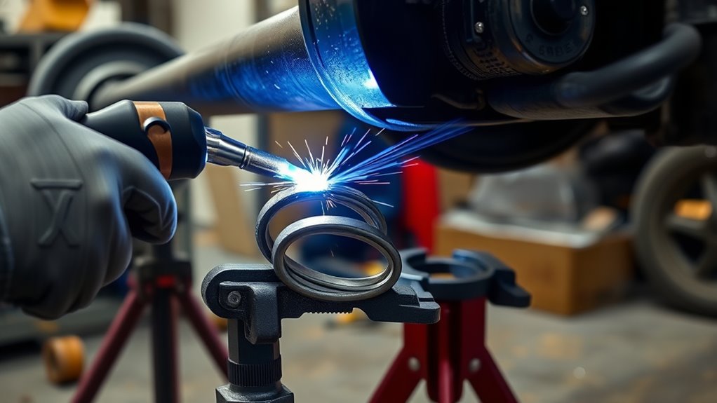
Once the axle sits centered and the perches match the planned positions, place small, sound tacks on both perches. Tack in a balanced sequence so one side does not pull before the other. Let the tacks cool, then repeat every measurement before committing to the final welds.
Do not fully weld one perch while the other remains loose. Heat and weld shrinkage can rotate or pull the first perch. Balanced tacks hold the fit-up while still allowing you to remove a tack if the spacing or angle changes.
- Confirm both spring center pins seat fully in the perch holes.
- Check that both saddles contact the axle tube without a visible gap.
- Remeasure the axle from fixed chassis points and compare both diagonals.
- Verify the output, driveshaft, and pinion readings at ride height.
- Confirm clearance around brake lines, hoses, wiring, seals, shocks, and the fuel system.
- Mark the location of the work clamp for each side of the housing.
After the tacks cool, remove the axle for final welding when that gives safer access and keeps heat and sparks away from the vehicle. Support the housing in a stable fixture without twisting it. Protect open ends, vents, seals, and machined surfaces from grinding dust and spatter.
Weld Spring Perches Without Warping
Follow the axle and perch manufacturer’s weld pattern, weld size, filler-metal, and preheat instructions. There is no universal 3/4- to 1-inch segment length for every housing. When the approved procedure allows segmented welding, complete the required seams in short alternating passes, switching sides and perches to balance heat and shrinkage. Do not leave an intermittent structural weld unless the design specifically calls for one.
Use the smallest sound fillet weld that meets the approved design. Oversized beads add heat without automatically adding useful strength. TWI’s distortion guidance explains that uniform fit-up, adequate tacking, controlled heat input, and a balanced welding sequence help limit distortion.
Let the housing cool in still air unless the manufacturer’s welding procedure specifies another method. Do not quench the weld with water. Avoid uncontrolled heating or forced cooling that could increase residual stress or damage nearby seals and components.
MIG, flux-cored, or stick welding may be suitable when the process, filler metal, polarity, shielding, and machine output match the verified axle-tube and perch materials. Practice the joint on metal of the same type and thickness if you have any doubt. Stop if the arc will not fuse both edges cleanly, the tube overheats, or you cannot maintain the required bead profile.
Weld only the seams required by the perch design. Do not add random beads across unsupported edges, onto U-bolts, or onto the leaf springs. Leaf springs are heat-treated spring steel. EATON Detroit Spring warns that welding heat or spatter can create stress risers and lead to spring failure. Keep the leaves shielded from the arc and hot spatter.
Good fit-up and the correct completed weld matter more than an arbitrary bead length. Balance the sequence, control heat, and stop to remeasure before a small error becomes permanent.
Calculate and Confirm the Pinion Angle for Your Setup
Set the pinion angle before final welding and confirm it again after the housing cools. Do not compare only the pinion to the floor. Calculate the operating angle at each U-joint from the difference between the slopes of the two parts that meet at that joint.
For a conventional rear-wheel-drive shaft with one single-Cardan U-joint at each end, the transmission or transfer-case output and pinion are commonly set parallel in the same plane so the front and rear operating angles cancel each other. Verify the actual operating angles with the Spicer Driveline Operating Angle Calculator. Spicer recommends at least 0.5 degree of operating angle, equal angles within 1 degree, and generally no more than 3 degrees for vibration-free performance, subject to shaft-speed limits.
For a double-Cardan or CV-style shaft, follow the shaft manufacturer’s instructions. The double-Cardan joint handles most of the angle at one end, so the pinion usually points closer to the driveshaft centerline. The rear joint still needs the small angle specified by the manufacturer for bearing movement and lubrication.
Leaf-spring axle wrap can rotate the pinion upward under acceleration, but the amount varies with spring rate, torque, traction, load, and traction bars. Do not add a generic downward correction. Ask the driveshaft builder for the loaded target when the vehicle has a lift, high torque, a short shaft, compound angles, or a vibration history.
Use clean, repeatable surfaces such as the output-yoke face, driveshaft tube, and pinion-yoke face. Write down each slope and whether it rises or falls from front to rear. Recheck with normal tire pressure, the vehicle level, and the intended load.
Recheck Alignment After Welding
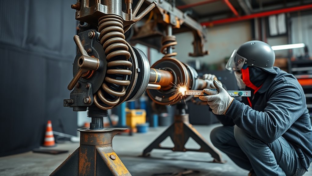
Let the housing cool naturally before taking final measurements. Then remeasure from the axle or brake flanges to the same fixed chassis points, compare the diagonals, and check the perch center-to-center distance. The axle should return to the recorded lateral position and remain square to the chassis.
Check the pinion angle and both U-joint operating angles again. Welding heat and shrinkage can move a perch even when the tacks looked secure. If the readings changed beyond the driveline manufacturer’s tolerance, correct the housing before final assembly.
Post-Weld Measurement Check
Recheck every critical dimension with the same tools and reference surfaces you used before welding. Switching reference points can hide a change.
- Measure from fixed chassis points to the axle on both sides.
- Compare both diagonals to confirm the axle remains square.
- Confirm the perches face the same direction and match the spring centerlines.
- Check that the spring center pins seat fully without forcing the axle sideways.
- Inspect brake lines, cables, hoses, shocks, seals, wiring, and vent parts for heat or spatter damage.
- Verify wheel, driveshaft, exhaust, shock, and bump-stop clearance through suspension travel.
Verify Pinion Angle
Install the axle with the correct hardware, place the vehicle at ride height, and measure the output, driveshaft, and pinion slopes again. Calculate the operating angle at both ends of the shaft. If the vehicle will carry a regular load, repeat the check at that load or use the driveshaft builder’s loaded target.
Correct an angle error before driving at road speed. Driveline vibration during acceleration, deceleration, or cruise can also come from shaft runout, balance, worn U-joints, compound angles, or a loose axle, so do not assume the pinion angle is the only possible cause.
Inspect Perch Welds
Inspect every weld in bright light after cleaning off slag and spatter. The bead should fuse into both the perch and axle tube, follow the required seam, and show no cracks, visible lack of fusion, large pores, overlap, severe undercut, or missed edges. Do not grind a structural fillet weld flush for appearance. If the joint is questionable, have a qualified welder inspect and repair it.
After inspection, clean and coat the bare steel with a compatible primer and chassis finish. Keep paint off spring contact surfaces, threads, brake friction surfaces, and any area where the hardware manufacturer requires clean metal-to-metal contact.
Install U-bolts that match the axle diameter, spring pack, plate, thread, and strength requirements. Torque the nuts evenly in a crisscross sequence to the vehicle, spring, or U-bolt manufacturer’s specification. Do not guess from bolt diameter alone. EATON Detroit Spring recommends new U-bolts for spring installation and warns that reused rolled threads may not maintain the required clamp load.
Note: Recheck U-bolt torque at the interval specified by the vehicle, spring, or hardware manufacturer. Paint, surface coatings, and newly assembled spring packs can settle, but the correct interval and torque depend on the exact hardware.
Final Road Check
Before normal driving, check brake operation, fluid leaks, driveshaft clearance, shock travel, parking-brake cables, axle vent routing, and every fastener. Perform a short, low-speed test in a safe area. Listen for clunks and scraping, and feel for vibration or a vehicle that does not track straight.
Stop immediately if you notice a loose axle, shifting U-bolts, a cracked weld, a new driveline vibration, tire rub, brake-line contact, or dog tracking. Reinspect the installation after the test and obtain a professional alignment or driveline check when the vehicle has a suspension-height change, an axle swap, or any questionable measurement.
Frequently Asked Questions
Can you weld leaf springs?
You should not weld the spring leaves, U-bolts, or clips. Leaf springs use heat-treated spring steel, and welding heat or spatter can change the material and create a crack-starting stress riser. Weld the correct perches to an approved axle tube, then clamp the axle to the springs with suitable hardware.
How do you attach leaf springs to an axle?
The axle rests on correctly positioned spring perches. Each spring center pin locates in the perch hole, and U-bolts clamp the axle, spring pack, and plate together. The perches are welded to a compatible axle tube, but the springs and U-bolts are not welded.
What holds the leaf spring to the axle?
The perch supports and locates the axle, the center pin indexes the spring, and the U-bolts provide the clamping force. A damaged center pin, loose U-bolt, wrong perch, or weak weld can allow movement, so inspect the entire connection rather than one part alone.
Can you put leaf springs on top of an axle?
Yes. A spring-over-axle layout places the springs above the axle and often raises the vehicle. It also changes the center of gravity, driveline angle, axle wrap, shock and bump-stop travel, brake-hose routing, and handling. Treat the conversion as a full suspension redesign, not only a perch relocation.
Should you weld all the way around a spring perch?
Follow the perch and axle manufacturer’s weld drawing. Many perches use completed fillet welds along specified side seams rather than random beads around every open edge. Do not leave gaps in a required seam or add extra weld metal that increases heat without serving the design.
Can you drive right after welding the perches?
Drive only after the housing has cooled, the welds have passed inspection, the bare metal has been protected, the axle has been assembled with correct hardware, the brakes and lines are safe, and the axle position and U-joint operating angles have been verified. Begin with a low-speed test and inspect everything again.
Should you weld the perches with the axle in the vehicle?
Tacking in the vehicle can help preserve ride-height measurements, but final welding is often safer with the axle removed and supported in a fixture. Removal improves access and keeps heat and sparks away from the fuel system, brake parts, wiring, bushings, and underbody coatings.
Can you reuse leaf spring U-bolts?
Use new U-bolts when the vehicle, spring, or hardware manufacturer requires them, and replace any bolt that is rusty, stretched, damaged, cut, or previously torqued if reuse is not approved. Match the new hardware to the axle and spring pack, then torque and recheck it to the specified procedure.
Conclusion
After welding the leaf spring perches, verify the complete system before normal driving. Recheck perch spacing, axle centerline, diagonals, pinion angle, U-joint operating angles, weld quality, brake and shock clearance, and U-bolt torque. Correct measurement, verified materials, controlled welding, and careful inspection keep the rear axle secure and reduce the risk of vibration, poor tracking, or suspension movement.
Sources
- OSHA 1910.252 General Requirements – fire prevention, fire-watch duties, PPE, ventilation, coatings, and solvent precautions for welding.
- Spicer Measuring Angles – measuring driveline slopes and matching U-joint operating angles.
- Spicer Driveline Operating Angle Calculator – operating-angle calculations, minimum angle, matching tolerance, and speed-related limits.
- TWI: Distortion, Types and Causes – fit-up, tacking, heat input, and balanced welding-sequence principles.
- EATON Detroit Spring: Never Weld to a Spring – why welding heat and spatter can damage leaf springs.
- EATON Detroit Spring: Reinstalling U-Bolts – U-bolt thread deformation, replacement, and clamp-load guidance.