
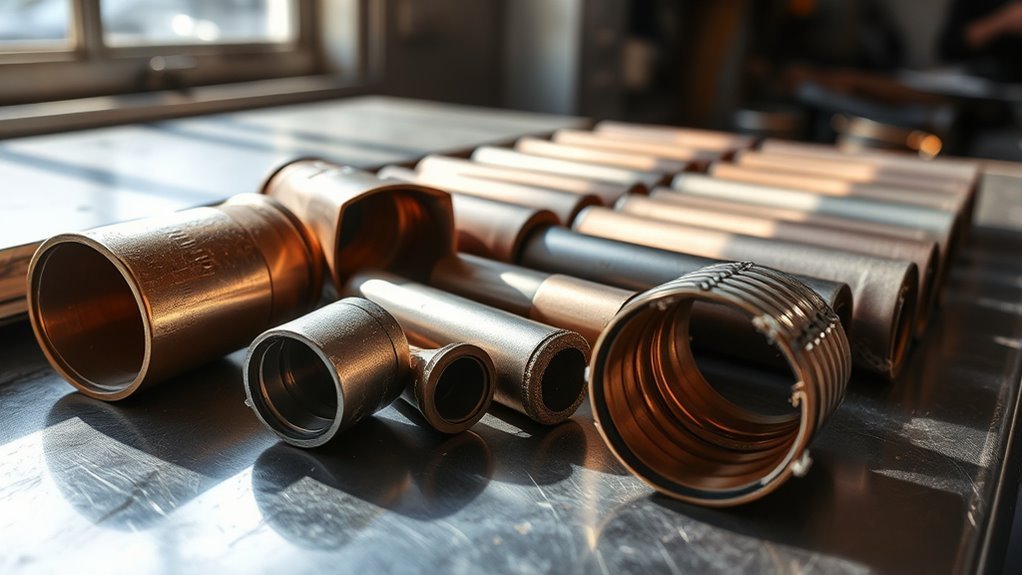
A MIG gun liner is easy to overlook because it sits inside the gun cable, but it has a direct effect on wire feeding and arc consistency. A dirty, kinked, incorrectly sized, or badly trimmed liner can contribute to wire drag, birdnesting, burnback, unstable feeding, and unnecessary strain on the drive system. This guide explains how to select, inspect, clean, troubleshoot, and replace a MIG gun liner without confusing liner problems with contact-tip, drive-roll, spool, or shielding-gas faults.
Quick Answer
A MIG gun liner guides welding wire from the feeder to the contact tip. Match its material, diameter range, length, and connection style to your gun and wire. Use an approved steel liner for compatible steel wires and a nonmetallic liner for aluminum. Replace it when cleaning and basic feed-system adjustments no longer restore smooth wire movement.
Key Takeaways
- Select the liner by gun model, cable length, wire material, and the manufacturer’s stated wire-diameter range.
- Use an approved steel liner for compatible steel wire and a PTFE, nylon, graphite, or other approved nonmetallic liner for aluminum.
- Do not diagnose a bad liner from birdnesting or burnback alone. Check the spool, drive rolls, contact tip, cable bends, and wire condition first.
- Straighten the gun cable during installation and trim the liner with the gun manufacturer’s gauge or specified dimension.
- Replace a kinked, crushed, heavily worn, corroded, or persistently clogged liner. There is no universal replacement interval for every shop.
At a Glance
| Time Required | About 20 to 45 minutes for a typical conventional liner, depending on the gun design and wire condition |
| Difficulty | Beginner to intermediate |
| Tools Needed | Welding pliers, gun-specific wrench or hex key, side cutters or liner cutter, trim gauge or manual, clean cloth, eye protection, and regulated compressed air if approved |
| Cost | Low, but it varies by gun length, liner material, loading system, and manufacturer |
Understanding the Function of MIG Gun Liners
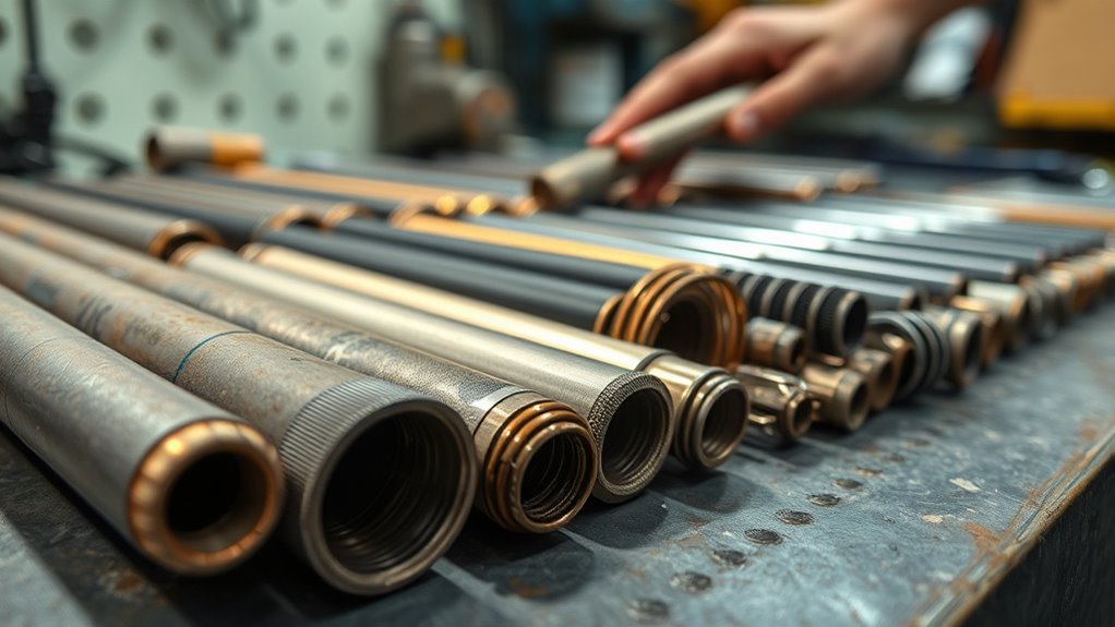
The liner is the replaceable guide that carries welding wire through the MIG gun cable and neck toward the contact tip. It supports the wire between the feeder and the front-end consumables so the drive rolls can push it without excessive wandering, buckling, or friction.
The complete wire path usually includes the spool, spool brake, inlet guide, drive rolls, outlet guide, gun liner, neck or jump liner, and contact tip. A restriction anywhere in this path can look like a liner problem, which is why the liner should not be replaced until the rest of the feed system has been checked.
According to Bernard and Tregaskiss liner guidance, the liner’s basic purpose is to guide welding wire from the feeder through the gun to the contact tip. It does not drive the wire by itself. The drive rolls supply the pushing force, while the liner keeps the wire supported and aligned.
Four liner characteristics must work together:
- Material: The liner surface must be compatible with the welding wire.
- Inside-diameter range: The liner must support the selected wire without pinching it.
- Length: The liner must match the gun cable and be trimmed correctly at the front or rear connection.
- Connection design: The liner must fit the gun’s power pin, neck, retainer, seal, and loading system.
Note: Liner color codes, part numbers, trim lengths, and wire-size ranges are not universal. Always confirm the replacement against the MIG gun manual or the gun manufacturer’s compatibility chart.
Steel vs. Plastic: Which Liner Material Should You Choose?
Start with the welding-wire material rather than choosing a liner by price or appearance. Hard steel wire and soft aluminum wire place very different demands on the feed path.
Products Worth Considering

Perfect for Aluminum Welding: The Graphene Welding Liner is adaptable to aluminum, copper, and other soft metal welding wire.
For Aluminum Welding: The Graphene Welding Liner is adaptable to aluminum, copper, and other soft metal welding wire, compatible with a wide range of wire sizes ( .030"-.045").

Premium Tweco style MIG welding gun Teflon conduit liner 35T-40-15 and 45T-40-15 for use with soft metal MIG welding wire. 15-ft long. Random colors; colors vary by batch.
Material Properties Comparison
Steel liners use a wound metal construction that supports compatible steel solid and cored wires. They are durable and common in general fabrication, repair, and production welding.
Nonmetallic liners may use PTFE, nylon, graphite, polyamide, or another low-friction material specified by the gun manufacturer. Their smoother surface helps reduce shaving and drag when feeding soft aluminum wire.
Some manufacturers also offer composite or reinforced nonmetallic liners for specific temperatures, wire alloys, or gun designs. Terms such as PA, composite PA, graphite, and reinforced liner do not describe one universal performance class. Use them only when the manufacturer lists the liner for your gun, wire, and duty cycle.
Application Suitability
Use the following table as a starting point, then verify the exact liner part number with the gun manufacturer.
| Wire or Application | Common Liner Family | Important Check |
|---|---|---|
| Carbon-steel solid wire | Approved steel liner | Match the liner range, contact tip, and drive-roll groove to the wire diameter. |
| Stainless-steel wire | Gun-approved steel or specialty liner | Follow the filler-metal and gun recommendations, especially when controlling cross-contamination matters. |
| Flux-cored or metal-cored wire | Approved steel liner | Cored wire and knurled rolls can create more debris, so inspect the liner and front-end consumables regularly. |
| Aluminum wire | Approved PTFE, nylon, graphite, or other nonmetallic liner | Use smooth feeding components, minimize cable bends, and consider a spool gun or push-pull system when necessary. |
| Silicon-bronze or specialty alloy | Manufacturer-specified steel or nonmetallic liner | Check the wire producer’s feedability guidance instead of assuming it uses the same setup as mild steel. |
ESAB’s aluminum GMAW setup guidance recommends nonmetallic liners and a feed path with as few bends as possible. Aluminum is softer than steel, so a rough or contaminated steel liner can shave the wire and increase drag.
Cost and Longevity
A liner’s purchase price matters less than the downtime caused by poor feeding. An inexpensive liner that does not match the gun or wire can waste contact tips, welding wire, labor, and troubleshooting time.
There is no reliable universal rule that every liner should last a set number of months. Service life depends on:
- Wire material, surface condition, and diameter
- Solid, metal-cored, or flux-cored construction
- Daily arc time and wire throughput
- Drive-roll pressure and spool-brake adjustment
- Gun cable length, bends, loops, and handling
- Dust, grinding debris, moisture, and corrosion
- Correct liner trimming and installation
For occasional shop use, inspect the liner when feeding changes or when you service the gun. High-volume operations can track wire usage, feed-motor load, contact-tip failures, and liner-related downtime to establish a preventive replacement interval for that specific application.
Exploring Different Types of MIG Gun Liners
MIG gun liners differ not only by material and diameter but also by how they load into the gun and how much of the wire path they support.
Types of MIG Liners
- Conventional rear-load liners: These enter through the power-pin end of the gun and run through most or all of the cable. The gun is normally laid straight before removal and installation.
- Front-load liners: These can be replaced from the neck end on compatible guns, reducing the need to disconnect the gun from the feeder after the system has been set up.
- Auto-length or spring-loaded liners: These systems maintain contact between the liner and front-end components to reduce gaps caused by inaccurate trimming or cable movement.
- Jump or neck liners: These short liners support the wire through a replaceable neck section. They are common in some industrial, robotic, and high-use guns.
- Push-pull gun liners: These are designed for systems that combine feeder rolls with powered rolls in the gun. They often use nonmetallic liners for aluminum.
- Spool-gun liners: A spool gun carries a small wire spool on the gun, so the wire travels through a much shorter path. Its liner and consumables remain model-specific.
Bernard provides separate procedures for rear-load liners, front-loading liners, and jump liners. Identify your system before loosening retainers or cutting the replacement.
Material Considerations
Steel liners are a practical choice for many compatible steel solid and cored wires. Inspect them for corrosion, crushed coils, metal debris, and polished or worn areas near bends.
Nonmetallic liners reduce friction for aluminum and other soft wire, but they can be damaged by excessive heat, sharp tools, overtightened retainers, and careless trimming. Use a clean cutter recommended for the liner material so the end remains round and free of burrs.
When changing from steel to aluminum, clean the entire feed path. A new nonmetallic liner will not solve the problem if the drive rolls, inlet guide, contact tip, or gun connection remains packed with steel dust or damaged wire shavings.
Size Matching Importance
The replacement liner should list a wire-diameter range that includes your welding wire. Do not select it only because it physically fits inside the gun.
- Too small: The wire may drag, shave, jam, or stop when the cable bends.
- Too large: Small wire may lose support, wander inside the liner, and buckle more easily when resistance develops downstream.
- Too short: A gap may remain between the liner and diffuser, tip adapter, neck liner, or power-pin guide.
- Too long: The liner may compress, distort, interfere with assembly, or create extra friction.
Use the gun manufacturer’s liner chart, not a generic color chart. A color used for one wire range by one brand may identify something different on another system.
Why Liner Diameter Matters for Wire Feeding
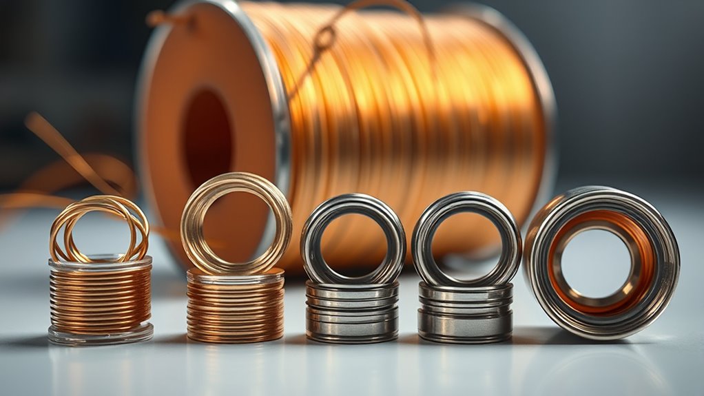
The liner must support the wire while leaving enough clearance for it to move through normal cable curves. When the fit is wrong, the drive rolls must overcome unnecessary resistance or push poorly supported wire through the gun.
An undersized, damaged, or clogged liner can increase drag. The wire may slow down, surge, slip at the drive rolls, or buckle between the rolls and the gun inlet.
An oversized liner does not usually create porosity by itself. Its main effect is reduced wire support, particularly with small or soft wire. Porosity should be traced separately by checking gas flow, cylinder supply, regulator and hose condition, power-pin seals, liner-retainer O-rings where applicable, diffuser passages, nozzle blockage, drafts, and workpiece contamination.
A liner problem changes how the wire moves. A sealing, diffuser, nozzle, or gas-delivery problem changes how shielding gas reaches the weld. Test the two systems separately before replacing parts.
How to Know When to Replace Your MIG Gun Liner
Replace the liner based on its condition and feeding performance rather than a universal calendar interval. A production gun may wear out a liner quickly, while an occasional-use gun may keep the same liner much longer.
Replacement is usually justified when you find one or more of these conditions:
- A permanent kink, crushed area, split jacket, or distorted liner end
- Visible corrosion or heavy embedded debris
- Persistent wire drag after the tip and feed settings have been checked
- Repeated wire shaving or clogging
- A liner that was cut too short or damaged during installation
- A retainer, collet, seal, or O-ring that cannot hold the liner correctly
- Recurring birdnesting or burnback that disappears when a known-good liner is fitted
Check These Items Before Replacing the Liner
- Straighten the gun cable. Tight coils and sharp bends increase resistance even when the liner is usable.
- Inspect the wire spool. Look for crossed turns, rust, dirt, damaged edges, and wire trapped under another turn.
- Check spool-brake tension. The spool should not overrun, but excessive brake pressure makes the drive motor work harder.
- Confirm the drive rolls. Check the groove type, groove size, alignment, and pressure.
- Inspect the inlet and outlet guides. Misalignment can shave the wire before it enters the liner.
- Remove and inspect the contact tip. A worn, fused, dirty, or undersized tip can create the same symptoms as a restricted liner.
- Feed wire with the tip removed. If feeding becomes smooth, the tip or front-end alignment is more likely to be the restriction.
- Inspect the liner. Replace it if cleaning does not restore free wire movement or if physical damage is visible.
Warning: Turn off and unplug the welding power source and feeder before removing the wire, gun parts, or liner. Control the loose wire end because welding wire can spring off the spool and cause an eye or puncture injury.
Essential Maintenance Tips for MIG Gun Liners
Good liner maintenance starts with keeping contaminants out of the wire path. Store welding wire in a clean, dry area, keep the feeder closed when practical, and avoid laying the gun where grinding dust can enter the nozzle or power-pin connection.
- Inspect during spool changes: Check for excessive wire dust, rust, shaved metal, and changes in feed resistance.
- Keep the cable in broad curves: Avoid dragging the gun by its cable or storing it in tight coils.
- Use correct drive pressure: Excess pressure can deform soft wire and create debris; too little pressure allows slipping.
- Check the contact tip: A damaged tip can cause burnback and may be mistaken for a liner restriction.
- Protect liner seals: Inspect the retainer, collet, jacket, and O-ring used by your gun design.
- Document repeated failures: If liners clog frequently, record the wire type, drive settings, gun position, and failure point instead of replacing parts without finding the cause.
Some gun manuals instruct users to blow debris from the gun casing or liner with compressed air during service. Follow the gun manufacturer’s method. Remove the wire first unless the manual states otherwise, use dry regulated air, wear eye protection, and direct the outlet away from yourself and other people.
Pro Tip: If the liner repeatedly fills with metal shavings, inspect the drive-roll groove, roll alignment, inlet guide, wire surface, and front-end trim. A new liner will clog again if another component keeps shaving the wire.
How to Properly Install a MIG Gun Liner
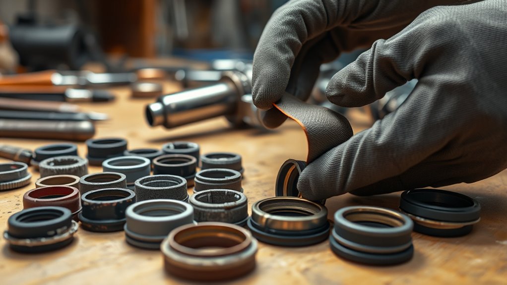
The following procedure covers a common conventional rear-load liner. Front-load, auto-length, push-pull, spool-gun, and jump-liner systems use different retainers and trim points. Read the gun manual before cutting the replacement.
Tools and Supplies
- Correct replacement liner for the gun, cable length, and wire range
- Gun-specific wrench, spanner, or hex key
- Welding pliers
- Side cutters or the manufacturer’s liner-cutting tool
- Supplied trim gauge or the gun manual’s trim dimension
- Clean cloth
- Safety glasses with side protection
- Dry regulated compressed air if the manufacturer approves its use
Replacement Steps
- Shut down the equipment. Turn off and unplug the power source and feeder. Close the shielding-gas cylinder if the gun will be disconnected.
- Control and unload the wire. Release drive-roll pressure. Cut the wire cleanly near the feeder and rewind it onto the spool while keeping hold of the loose end. Secure the wire in the spool’s retaining hole.
- Straighten the gun cable. Lay the gun and cable out in a straight line. This reduces friction and helps prevent the new liner from kinking.
- Remove the front-end consumables. Take off the nozzle, contact tip, diffuser, retaining head, or tip adapter as required by the gun design.
- Release the old liner. Disconnect or loosen the liner set screw, collet, retaining nut, or threaded liner lock at the power pin. Do not overtighten or force small fasteners.
- Pull out the old liner. Remove it while keeping the gun straight. Examine the first damaged or dirty area because its location may reveal a sharp cable bend, trimming problem, or misaligned guide.
- Clean and inspect the gun. Check the cable, power pin, neck, guides, diffuser, seals, and O-rings. Blow out the casing only when the manufacturer permits it.
- Insert the replacement. Feed the new liner through the gun in short, controlled strokes. Twist it gently only if the manufacturer allows that method. Do not force it past an obstruction.
- Seat and secure the liner. Make sure the retainer, collet, liner lock, shoulder, or O-ring is fully seated. Tighten it to the specified method or torque without crushing the liner.
- Trim it to the specified length. Use the supplied gauge or exact manual dimension. Do not copy a trim length from a different gun.
- Remove burrs. Make a square, clean cut. Inspect the opening and pass a clean piece of the correct wire through it to confirm that the cut did not pinch or obstruct the bore.
- Reassemble the gun. Reinstall the diffuser, adapter, contact tip, and nozzle in the correct order.
- Reload the wire. Confirm the drive-roll groove and contact-tip size, guide the wire into the inlet, and apply only enough roll pressure to feed without slipping.
- Test before welding. Feed several feet of wire at a low or moderate speed while the cable is straight, then test it through normal broad curves. Listen for surging and watch for wire dust or birdnesting.
- Check the gas system. Restore the shielding gas and inspect applicable gun connections, seals, diffuser openings, and hose joints for leakage or blockage.
A gun-specific MIG liner replacement guide can provide additional model examples, but the gun manufacturer’s manual controls the final trim dimension and retainer method.
Note: Some modern front-load and auto-length systems are intentionally trimmed flush at a power pin or with a proprietary gauge. Other conventional guns require a measured amount of liner beyond the neck. These instructions are not interchangeable.
Troubleshooting Common MIG Gun Liner Issues
Use the symptom as a starting point, not as proof that the liner has failed.
| Symptom | Possible Causes | What to Check |
|---|---|---|
| Jerky or surging wire feed | Dirty or kinked liner, damaged tip, spool drag, incorrect rolls, low roll pressure, tangled wire | Straighten the cable, remove the tip, inspect the spool and guides, then test the liner. |
| Birdnesting near the drive rolls | Downstream restriction, excessive roll pressure, misaligned guide, wrong liner or tip, sharp cable bend | Find the restriction before increasing drive pressure. More pressure can make the buckle worse. |
| Burnback into the contact tip | Wire-feed interruption, worn tip, incorrect tip size, poor parameter balance, liner restriction | Replace the fused tip, confirm wire speed and voltage, then isolate the liner and feed path. |
| Metal shavings in the liner | Rough or wrong liner, misaligned guides, excessive roll pressure, knurled rolls, damaged wire | Correct the shaving source before installing another liner. |
| Wire feeds straight but binds when the cable bends | Wrong liner range, liner wear, cable damage, tight bend radius, soft wire in a long push system | Inspect the cable and liner, reduce bends, and consider a spool or push-pull gun for aluminum. |
| Porosity or weak gas coverage | Gas leak, damaged applicable O-ring, blocked diffuser or nozzle, draft, wrong flow, empty cylinder, contamination | Test the gas system separately. Do not assume liner diameter caused the porosity. |
How to Isolate Liner Resistance
With the welder shut down, remove the contact tip and straighten the cable. After safely restoring only the wire-feed function as directed by the equipment manual, feed wire through the gun. If the wire feeds smoothly with the tip removed, inspect the tip and front-end alignment. If it still surges or slips, inspect the guides, liner, cable, spool brake, and drive system.
Do not pull energized wire by hand or bypass guards and interlocks. If the feeder must operate during a test, keep your hands away from the drive rolls and point the gun away from people.
Choosing the Right Liner for Optimal Performance
Use this selection order when buying a replacement:
- Identify the gun: Record the gun brand, model, amperage family, cable length, power-pin style, and neck system.
- Identify the wire: Record the alloy, solid or cored construction, diameter, and surface condition.
- Choose the approved material: Use the manufacturer’s recommended steel or nonmetallic liner family.
- Confirm the diameter range: The exact wire size must fall within the liner’s published range.
- Confirm the loading system: Rear-load, front-load, auto-length, jump, spool-gun, and push-pull liners are not automatically interchangeable.
- Confirm the length: Match the cable length and allow only the trimming method specified for that liner.
- Check related consumables: Match the drive-roll groove, inlet guide, outlet guide, diffuser, and contact tip to the same wire.
For aluminum, the liner is only one part of the setup. ESAB’s aluminum feedability guidance recommends treating the spool, rolls, guides, liner, cable route, and contact tip as one system. Softer aluminum alloys and smaller diameters can be especially difficult to push through a long or sharply curved gun cable.
If you also run self-shielded or gas-shielded flux-cored wire, verify that the liner and drive rolls support the wire used with your flux-core MIG welding settings.
Products Worth Considering


Package list: 1-PK liner
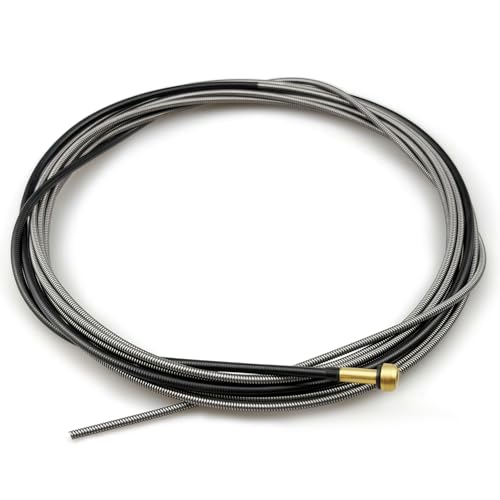
【Precise Fit for Lincoln Welding Guns】Specifically designed for Lincoln MIG guns, compatible for Magnum 100L, for Magnum PRO 100L/175L. Mig liner Directly replaces OEM part KP35-40-15, Mig liner kp1937-3 easy to install without extra modification
Common Mistakes to Avoid With MIG Gun Liners
- Buying by wire size alone: The liner must also match the gun, cable length, retainer, and loading style.
- Assuming color codes are universal: Always verify the manufacturer’s part number.
- Forcing the liner: Resistance may indicate a sharp bend, damaged cable, blocked neck, or wrong component.
- Installing it with the cable coiled: This increases the chance of kinking and inaccurate trimming.
- Guessing the trim length: A small gap or excess length can create a feed restriction.
- Leaving a burr after cutting: A crushed or sharp liner end can scrape the wire immediately.
- Overtightening a set screw or collet: This can distort the liner or prevent free wire travel.
- Using a dirty steel feed path for aluminum: Steel debris and rough surfaces can shave soft aluminum wire.
- Increasing roll pressure to overcome a blockage: Excess pressure can deform wire and worsen birdnesting.
- Replacing only the liner: A damaged contact tip, misaligned guide, tight spool brake, or poor cable handling can damage the replacement.
- Blaming porosity on liner diameter: Inspect the gas supply, seals, diffuser, nozzle, drafts, and workpiece condition.
Frequently Asked Questions
How often should I replace my MIG gun liner?
There is no universal replacement interval. Inspect and replace the liner when it becomes kinked, crushed, corroded, incorrectly trimmed, heavily contaminated, or unable to feed wire smoothly after the spool, drive rolls, guides, cable bends, and contact tip have been checked. Production shops can establish their own preventive interval from documented wire usage and failure history.
How can you tell if a MIG liner is bad?
Common signs include persistent wire drag, surging, repeated birdnesting, wire shavings, corrosion, visible kinks, and feeding that becomes worse when the cable bends. These symptoms can have other causes, so remove the contact tip and check the spool, brake, drive rolls, guides, and wire before condemning the liner.
Are all MIG gun liners the same?
No. Liners differ by material, inside-diameter range, cable length, retainer, power-pin connection, loading direction, trim method, and intended wire. A liner that fits one gun may not seat or seal correctly in another.
Can the wrong liner size cause birdnesting?
Yes. An undersized or restricted liner increases drag, while an oversized liner can provide poor support for small or soft wire. Birdnesting can also come from excessive drive-roll pressure, a blocked contact tip, a misaligned guide, spool drag, or sharp cable bends.
Can I clean a MIG liner instead of replacing it?
Cleaning may help when the liner contains loose dust or wire debris and has no physical damage. Follow the gun manual, remove the wire safely, and use dry regulated air only when approved. Replace the liner if it is kinked, crushed, corroded, cut incorrectly, deeply contaminated, or still restrictive after cleaning.
Can I run aluminum wire through a steel MIG liner?
A standard steel liner is generally a poor choice for soft aluminum wire because it can increase scraping, shavings, drag, and contamination. Use the nonmetallic liner, drive rolls, guides, and contact tip recommended for the aluminum wire and gun. A spool gun or push-pull gun may be more reliable for difficult feed paths.
Do I need respiratory protection when servicing or using a MIG gun?
Replacing a liner does not normally generate welding fumes, but compressed air can eject dust and metal particles, so wear eye protection and control the discharge. During welding, use source extraction or suitable ventilation. Respiratory protection is required when the material, safety data, exposure assessment, confined-space conditions, or applicable safety rules show that ventilation and work practices are not enough.
Conclusion
Your MIG gun liner should guide the wire with low, consistent resistance. Choose it by gun model, cable length, loading system, wire material, and wire-diameter range rather than by appearance or a generic color code.
Do not replace the liner automatically every few months or blame it for every birdnest, burnback, or porosity problem. Straighten the cable, inspect the spool and drive system, remove the contact tip, and isolate the restriction first.
When replacement is necessary, keep the gun straight, seat the correct liner fully, follow the manufacturer’s trimming method, remove every burr, and test the wire feed before welding. Those steps protect the new liner and help the complete feed system run smoothly.
Sources
- Miller, Top Factors and Considerations for MIG Gun Selection — liner sizing, gas seals, O-rings, and gun compatibility
- Bernard and Tregaskiss, Understanding MIG Gun Liners — liner purpose and wire-feed function
- Bernard and Tregaskiss, Steps for Proper MIG Gun Liner Installation — straightening, insertion, gauges, trimming, and front-load systems
- ESAB, Basics of Aluminum GMAW Machine Set-Up — nonmetallic liners and aluminum wire-feed setup
- OSHA, Ventilation and Protection in Welding, Cutting, and Heating — ventilation and welding-fume control
- OSHA, Respiratory Protection — respirator selection and respiratory-protection program requirements




