You’ll match amperage, air pressure, tip size, and travel speed to steel thickness to keep kerf narrow and cut quality high. For example, 1/16 in runs 15–20 A at 50–55 psi; 1/8 in needs 21–30 A at 55–60 psi; 1/4 in holds 40 A at 65–75 psi. You’ll also account for pierce delay, duty cycle, and material type to prevent dross and warping—then tune for speed without sacrificing edge integrity.
Power and Air Settings for Common Steel Thicknesses
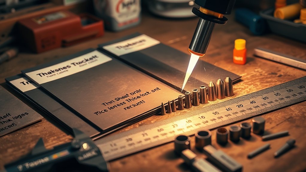
Set amperage and air pressure to match steel thickness so the arc fully penetrates and evacuates molten metal without excess dross. For 1/16 in (1.6 mm) steel, set 15–20 A with 50–55 psi. For 1/8 in (3.2 mm), use 21–30 A at 55–60 psi. For 3/16 in (4.8 mm), run 31–40 A and 65–70 psi. For 1/4 in (6.4 mm), apply the full 40 A with 65–75 psi.
Verify air quality—dry, oil-free supply—to stabilize arc voltage and increase plasma efficiency.
Ensure air is dry and oil-free to stabilize arc voltage and boost plasma cutting efficiency.
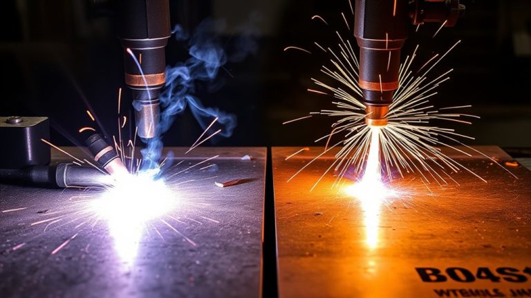
Monitor cut indicators: a near-vertical kerf face, minimal top spatter, and a trailing spark stream of 10–15° under the plate confirm correct parameters. If dross forms or the arc stumbles, increase pressure within the listed ranges before adding amperage. If edges bevel or the cut fails to separate, raise amperage incrementally.
Log settings by thickness, nozzle-orifice class, and site air temperature/humidity to maintain repeatable, standards-compliant results.
Understanding Kerf, Tip Size, and Consumable Selection
You’ll quantify kerf width as a function of amperage, air pressure, travel speed, and tip orifice, noting a 40 A system typically yields ~0.9 mm (0.035 in) kerf with correct parameters.
You’ll size the tip to your set current (31–40 A at 65–70 psi) and material, using FineCut for thinner stock to tighten the arc and reduce kerf while maintaining cut quality up to ~3/8 in at 40 A.
You’ll extend consumable life by matching amperage to tip rating, maintaining clean, dry air, correct stand-off, and appropriate travel speed to prevent double-arcing and premature wear.
Kerf Width Factors
Although kerf is simply the width of material removed by the arc, controlling it hinges on three variables: tip (nozzle) size, amperage, and consumable type.
You manage kerf width to preserve cutting accuracy and material yield. With a 40 amp plasma cutter on mild steel, a standard tip typically produces about 0.9 mm (0.035 in) kerf.
Larger tips widen the jet and increase kerf; smaller tips tighten the arc column and reduce it. Amperage scales the thermal input: higher amps broaden the melt zone and widen the cut, while properly reduced current narrows it without risking arc instability.
Consumables matter: FineCut sets generate a tighter arc profile that narrows kerf on thin sheet, improving precision.
Plan offsets and lead-ins to accommodate expected kerf in layouts.
Tip Orifice Sizing
Because the nozzle orifice sets the arc diameter and energy density, tip size dictates kerf and cut quality. For a 40 amp machine, you’ll typically run a 0.9 mm (0.035 in) tip. At 31–40 A and 65–70 psi, this orifice delivers stable tip performance and a predictable kerf on mild steel. Larger orifices widen kerf and soften edge definition; smaller or FineCut orifices tighten kerf and improve detail on thin sheet. Use orifice comparison data to match amperage, pressure, and material.
| Tip/Consumable | Setpoints (A/psi) | Typical Kerf |
|---|---|---|
| 0.9 mm Standard | 31–40 A / 65–70 psi | ~1.2–1.6 mm |
| FineCut | 28–35 A / 60–65 psi | ~0.8–1.1 mm |
| Oversize (1.0 mm) | 36–40 A / 70–75 psi | ~1.6–2.0 mm |
For copper, expect higher current demand—roughly double steel—to maintain cut quality and kerf control.
Consumable Lifespan Tips
When you align kerf targets with the correct tip size and amperage, consumables last longer and cut quality stays within spec. For a 40‑amp tip, expect a kerf near 0.9 mm (0.035 in). Use that baseline to verify cut width and detect drift from wear indicators like tip orifice growth, erratic arc starts, and bevel increase.
Match amperage to material thickness; excess current accelerates nozzle and electrode erosion. For thin sheet, FineCut consumables deliver a narrower kerf and more stable arc, extending life and improving detail.
Set air pressure to spec: low pressure causes dross and double‑arcing; high pressure widens kerf and slows speed. Execute disciplined consumable maintenance—inspect, log cut counts, and replace on schedule to reduce costs and maintain repeatable quality.
Setup Tips to Minimize Warping on Thin Sheet
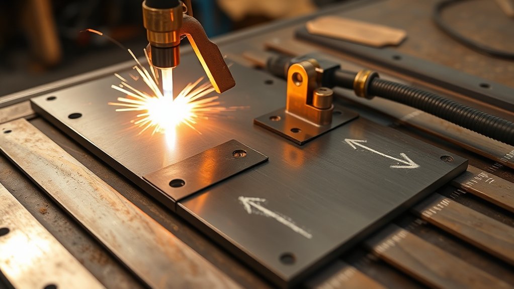
Even on thin sheet, you can limit distortion by controlling restraint, heat input, and arc characteristics before you strike an arc. Start with rigid fixturing: use clamping techniques that support the panel near the cut path and across edges to prevent flutter. Don’t stack sheets; it traps heat and degrades the bottom surface. Apply heat management fundamentals—maximize travel speed, minimize dwell, and avoid unnecessary pierces. Select FineCut consumables to produce a narrow kerf and a stiffer arc column that reduces lateral heat spread. Set amperage to match thickness on your 40 A system; overcurrent widens kerf and raises heat input.
Use the table to validate setup choices before cutting:
| Control | Specification/Target |
|---|---|
| Restraint | Full-contact clamps within 25–50 mm of path |
| Amperage | Match chart for alloy/thickness at ≤40 A |
| Standoff | 1.0–1.5 mm (maintain with THC if available) |
| Travel speed | High; verify a smooth, bright kerf with minimal dross |
| Consumables | FineCut set, new nozzle/electrode pairs |
Recommended Cut Speeds and Pierce Delays by Thickness
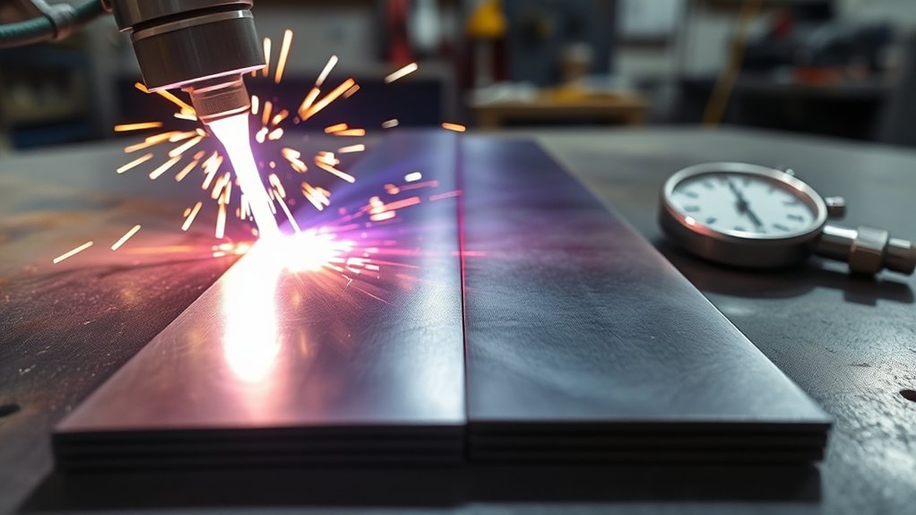
You’ll set speed ranges by gauge using baseline data: e.g., at 40 A, target ~35 IPM for 1/8 in mild steel and ~20 IPM for 1/4 in.
Calibrate pierce delay to thickness and material—about 0.5 s for 1/8 in, 1.0 s for 1/4 in mild steel, and up to 1.5 s for thicker stainless.
Material-specific tweaks include holding 40 A on 3/16 in mild steel with ~0.035 in kerf and maintaining ≥15 IPM travel to limit heat and dross.
Speed Ranges by Gauge
Speed ranges by gauge translate thickness into actionable settings—cut speed (IPM) and pierce delay (s)—so you can dial in clean kerfs and consistent edge quality. Use gauge comparison to standardize expectations and maximize speed efficiency under 40 A output. As thickness drops, velocity rises and pierce time shortens. Validate results with consistent torch height and dry air.
- 12 ga (0.105 in): run ~25 IPM, 0.5 s delay.
- 14 ga (0.075 in): run ~35 IPM, 0.2 s delay.
- 16 ga (0.060 in): run ~45 IPM, 0.1 s delay.
- 18 ga (0.048 in): run ~55 IPM, 0.05 s delay.
- 20 ga (0.035 in): run ~65 IPM, 0.0 s delay.
| Gauge | Cut Speed (IPM) | Pierce Delay (s) |
|---|---|---|
| 12 | 25 | 0.5 |
| 16 | 45 | 0.1 |
| 20 | 65 | 0.0 |
Tune by observing dross: slow for top bevel, speed up for bottom dross, keep arc centered.
Pierce Delay Settings
Building on gauge-based speed tuning, set pierce delay and cut speed by thickness to control arc penetration, kerf quality, and dross.
Apply pierce delay adjustments so the arc fully perforates before motion, then run at stable IPM for maximum cutting.
For 16 ga (0.0598 in): 0.5 s delay, 35 IPM.
For 14 ga (0.0747 in): 0.7 s delay, 30 IPM.
For 12 ga (0.1046 in): 1.0 s delay, 25 IPM.
For 10 ga (0.1345 in): 1.2 s delay, 20 IPM.
For 3/8 in: 1.5 s delay, ~15 IPM.
Verify the pierce completes: look for a clean eject of molten material before travel.
If top-edge bevel or unpierced starts occur, increase delay in 0.1 s steps.
If top dross or wide kerf appears, reduce delay slightly or increase speed 5 IPM.
Keep torch height constant to maintain consistency.
Material-Specific Tweaks
Although every machine and torch vary, dial cuts by thickness using validated speeds, delays, and air settings for a 40 A process. Match material properties to cutting techniques: set air at 65–70 psi, observe manufacturer amperage charts, and scale speed and pierce delay to thickness. For 1/8 in mild steel, target 35 IPM to limit heat input and kerf. At 1/4 in, use a 1.0 s pierce delay to stabilize the arc. For 3/8 in, slow to ~20 IPM to control dross.
| Thickness | Speed/Delay |
|---|---|
| 1/8 in mild steel | 35 IPM |
| 3/16 in mild steel | 28–30 IPM (0.6 s delay) |
| 1/4 in mild steel | 24–26 IPM (1.0 s delay) |
| 5/16 in mild steel | 22–23 IPM (1.1 s delay) |
| 3/8 in mild steel | ~20 IPM (1.2 s delay) |
Verify cut face, kerf, and dross; adjust 5–10% as needed.
Duty Cycle Considerations for 40 Amp Machines
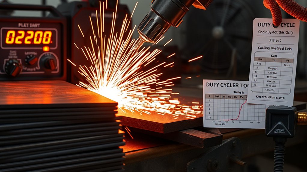
When planning cuts with a 40 amp plasma machine, treat duty cycle as a hard operating limit: most units rate 35–60% over a 10-minute interval, allowing 3.5–6 minutes of arc-on time before a required cool-down.
Use duty cycle monitoring for overheating prevention and to protect consumables and power electronics. Match your work rhythm to the rating; a higher duty cycle supports longer continuous cuts and tighter takt times, which is why models like the Hypertherm Viper 45 suit production.
- Calculate cycles: at 60%, cut 6 minutes, cool 4; at 35%, cut 3.5 minutes, cool 6.5. Plan nests accordingly.
- Control environment: maintain adequate ventilation; reduce ambient heat to sustain the effective duty cycle and stabilize thermal margins.
- Align thickness and speed: stay within the manufacturer’s cut-capacity window (typically up to 1/2 inch) to avoid extended arc-on time that triggers thermal limits.
- Instrument the process: log arc-on minutes, thermal trips, and fan duty; adjust schedule, amperage, or travel speed to keep utilization below rated thresholds.
Material-Specific Notes: Mild Steel, Stainless, and Aluminum
Because metallurgy drives cut behavior more than amperage alone, set expectations by alloy: a 40 A plasma cutter reliably pierces and cuts mild steel to 1/2 in (12.7 mm), stainless to 3/8 in (9.5 mm), and aluminum to 1/4 in (6.4 mm).
For mild steel, leverage its rigidity: run near 40 A, maintain adequate air pressure (per OEM spec), and use moderate travel speed to minimize dross and taper. Stainless steel demands tighter process control; reduce amperage slightly on thin sheet, increase travel speed, and keep torch-to-work distance consistent to limit warping. For aluminum cutting, prioritize high speed and dry, stable air to control heat input and avoid edge melt. FineCut consumables improve kerf fidelity on thin stainless and aluminum.
| Parameter focus | Alloy-specific note |
|---|---|
| Amperage trim | Stainless: drop slightly on thin gauges |
| Air pressure | All alloys: hold within spec to reduce dross |
| Travel speed | Aluminum: faster; mild steel: moderate |
Safety Essentials and Best Practices During Cutting
Process control by alloy only matters if you can cut safely and consistently. Treat a 40‑amp plasma setup as an arc‑producing, fume‑generating process: select safety gear first, then verify workspace organization.
Wear heavy‑duty gloves to prevent lacerations from thin sheet edges and post‑cut burrs. Use safety glasses with side shields; upgrade to a face shield when dross is heavy. Maintain cross‑flow ventilation or local exhaust, especially on painted or coated metals, to control particulate and fumes. Keep a class ABC fire extinguisher within reach; clear combustibles from the arc path and spark plume.
- Pre-checks: verify torch leads, ground clamp integrity, and dry, uncluttered flooring; stage parts and tools to minimize reach.
- During cut: stabilize stance, maintain cable management, and keep sparks directed away from hoses and cords.
- Fume control: position extraction at the plume, confirm airflow before arcing.
- Post-cut: allow cooling, mark hot parts, and deburr edges before handling or fixturing.
Frequently Asked Questions
How Do Ambient Temperature and Humidity Affect Plasma Cutting Performance?
They directly influence arc stability and cutting efficiency. You’ll see colder, dry ambient conditions improve duty cycle, gas density, and kerf quality; heat and high humidity raise resistance, promote condensation, degrade consumables, and require tighter gas standards, preheat control, and periodic calibration.
What Extension Cord Gauge Is Suitable for a 40-Amp Plasma Cutter?
Use 6‑gauge copper for 40‑amp continuous load at 120–240 V, ≤50 ft; step up to 4‑gauge beyond 50–100 ft to limit voltage drop <3%. Choose outdoor‑rated extension cord materials, NEMA plug compatibility, and GFCI protection.
Can a Generator Reliably Power a 40-Amp Plasma Cutter?
Yes—if the generator capacity matches continuous load and surge. For example, you’d reliably run a 40‑amp unit with a 9–10 kW generator, <5% THD, <3% voltage sag, preserving plasma cutter efficiency and duty cycle. Continuous‑rated preferred.
How Do I Troubleshoot Inconsistent Arc Starts or Frequent Arc Blowouts?
Check consumables, electrode-to-nozzle gap, and air quality/pressure (per manufacturer specs). Verify clean ground, correct lead routing, and proper pierce height. For arc stability, apply these troubleshooting techniques: update torch parts, eliminate moisture, shield from drafts, confirm steady input power.
Which Air Filtration or Dryer Setup Best Protects the Torch and Consumables?
Like armor for airflow, you’ll use a three-stage path: 5‑micron particulate prefilter, refrigerated dryer to 3‑5°C dew point, then 0.01‑micron coalescing filter with auto‑drain. Maintain 90‑120 psi, oil‑free air quality, maximizing consumable lifespan per ISO 8573-1.
Conclusion
You’ve now got a dialed-in matrix: 15–20 A at 50–55 psi slices 1/16 in like a laser; 21–30 A at 55–60 psi makes 1/8 in surrender; 40 A at 65–75 psi obliterates 1/4 in with surgical repeatability. Match kerf, tip, and consumables like you’re writing an ISO spec, and your cut speeds will sing. Manage duty cycle like it’s sacred. With these parameters, you won’t cut steel—you’ll command geometry with ridiculous, standards-grade authority.