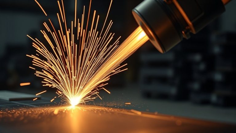
You want a 50A plasma cutter to deliver clean, repeatable cuts on steel and aluminum, but capacity hinges on voltage, duty cycle, gas quality, and technique. At 220V, expect clean cuts to 1/2 in; at 110V, plan for about 1/4 in on steel due to lower arc energy. Aluminum requires stable current and proper tips to maintain edge quality. Air pressure, torch height, and feed rate finish the equation—get any wrong, and performance drops fast.
Recommended Thickness Ranges for 50 Amp Plasma Cutters
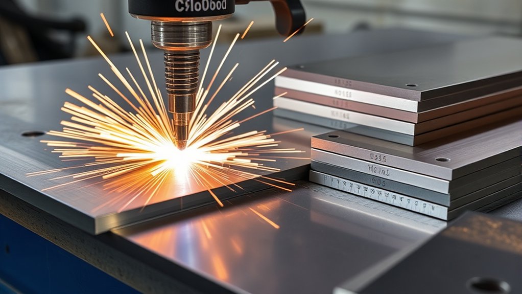
For most 50 amp plasma cutters, specify a clean-cut range of up to 1/2 in (12 mm) steel and aluminum, with a severance capability to about 5/8 in (16 mm) in steel.
Expect best results at 220 V, while 110 V typically limits clean cuts to ~1/4 in (6 mm) steel.
You should set expectations by material types and duty targets. For carbon steel and aluminum, plan production clean cuts at ≤1/2 in; reserve 5/8 in steel for noncritical severance.
Cutting speed must be calibrated to thickness and conductivity: increase travel rate on thinner sheet to avoid overburn, then reduce speed as thickness approaches capacity to maintain kerf quality and minimal dross.
Use correct consumables: a 3/64 in tip for 0–40 A work and a 1/16 in tip for 40–80 A to stabilize arc density and kerf width.
Verify consumable condition and torch standoff; worn tips degrade edge squareness, raise heat input, and reduce repeatability across workpieces.
Steel Cutting Performance at 110V Vs 220V
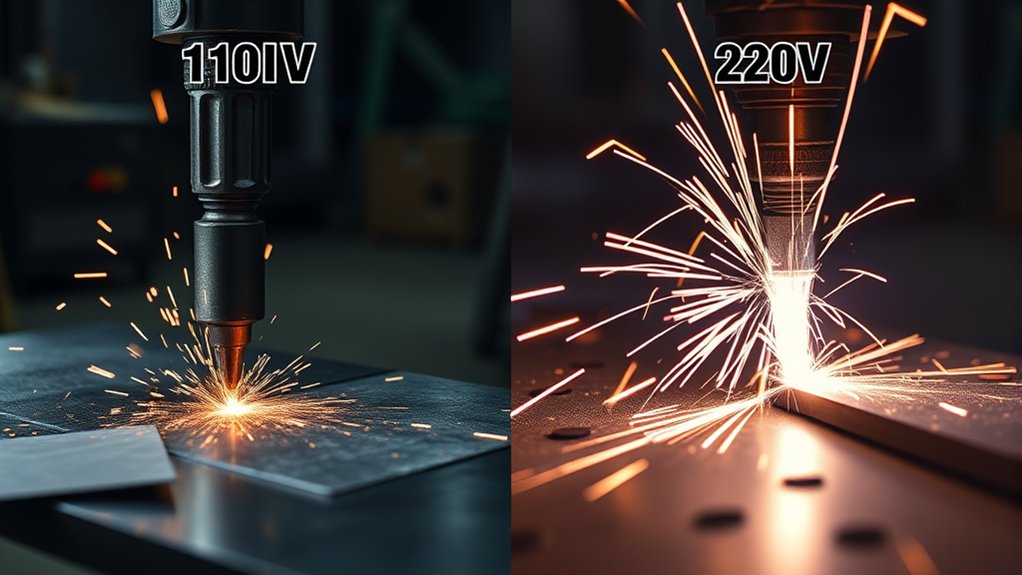
Two input voltages define how a 50‑amp plasma cutter performs on steel: 220V delivers full capacity, while 110V imposes clear limits. You’ll see clear voltage effects on thickness, duty cycle, and cut quality. At 220V, expect single‑pass cuts to 1/2 in (12 mm) with cleaner edges and minimal slag because the supply sustains current and arc stability. At 110V, capacity drops to 1/4 in (6 mm); arc energy is lower, kerf widens, and dross increases, demanding slower travel or secondary cleanup. Duty cycle also shifts: 60% at 220V enables longer continuous cutting versus 40% at 110V.
| Metric | 110V vs 220V |
|---|---|
| Max steel thickness (single pass) | 1/4 in vs 1/2 in |
| Duty cycle at 50 A | 40% vs 60% |
| Cut quality | More slag vs cleaner edge |
| Process stability | More fluctuations vs steadier arc |
Match input voltage to material thickness and productivity targets to maintain specification‑grade results.
Aluminum Cutting Performance and Best Practices
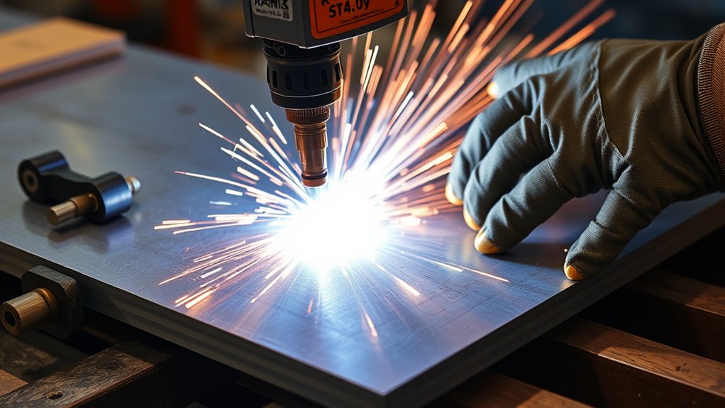
Although aluminum conducts heat rapidly and reflects energy differently than steel, a 50‑amp plasma cutter can deliver specification‑grade results when you match amperage, consumables, and air supply to thickness.
For plate up to 1/2 in (12 mm), you can achieve a clean cut using a stable current and correct torch setup. For thin sheet, drop current to 20–30 A to keep a tight arc, limit kerf, and control cutting speed. Step up toward 50 A as thickness increases to sustain energy density through aluminum oxidation and maintain edge squareness.
Use the correct tip: a 1/16 in orifice aligns with 40–80 A ranges and stabilizes the jet, reducing double‑arcing.
Keep standoff consistent and drag at a constant rate; too slow increases burring, too fast leaves dross freeze‑in.
Prioritize air quality: dry, oil‑free compressed air at about 4.5 psi and 6.0 CFM preserves arc stability, minimizes porosity, and exploits aluminum’s low slag behavior for minimal post‑processing.
Duty Cycle and Its Impact on Cutting Thickness
Because duty cycle governs how long the power source can sustain load before thermal shutdown, it directly limits practical cutting thickness and productivity. You measure it as a percent of a 10‑minute window. For example, a 30% duty cycle at 50A means 3 minutes cutting, 7 minutes cooling. That’s duty cycle importance: it constrains arc-on time and consequently your maximum continuous penetration on steel and aluminum.
Higher amperage reduces duty cycle, so pushing 50A on thicker sections forces more pauses, lowering cutting efficiency. Conversely, dropping current extends run time. At 220V, the VEVOR unit delivers 60% at 33A—6 minutes on, 4 off—supporting longer, consistent passes on medium thickness material.
Material thickness matters. Cutting 1/2‑inch steel depletes thermal capacity faster than 1/4‑inch aluminum, accelerating shutdown risk.
Plan jobs by matching amperage to thickness and scheduling cool-down intervals to maintain performance and prevent damage. Track actual arc time and stay within the published 10‑minute duty window.
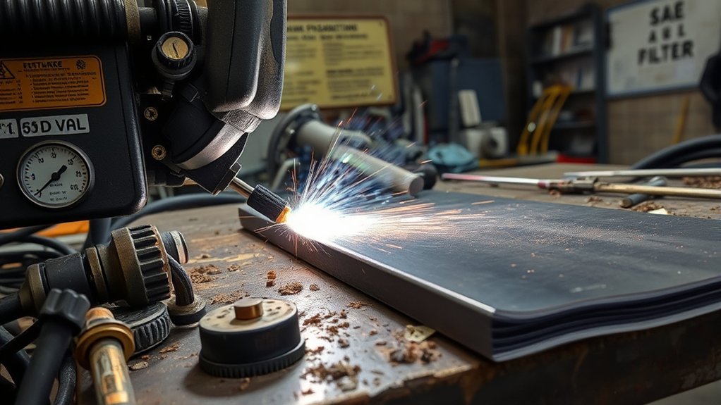
Air Pressure, Flow, and Gas Quality Requirements
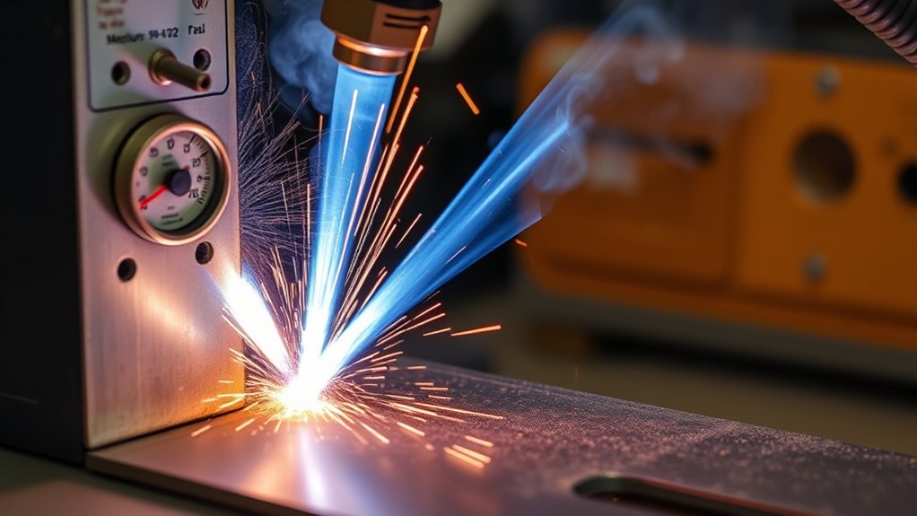
Set air delivery to meet the cutter’s spec, then verify it under load. For a 50 A unit like the VEVOR, target minimum air pressure of 4.5 PSI and flow of 6.0 CF/M at the torch while cutting, not just at idle. Use a compressor with volume capacity 1.5–2.0× the plasma demand to maintain stable flow during long cuts. Monitor pressure decay and recover time; insufficient pressure yields incomplete cuts, while excess pressure increases dross and slows travel speed.
Use clean, dry, non-hazardous compressed air. Prioritize gas quality with filtration and drying to prevent moisture-induced arc instability and porosity. Adjust flow to material thickness: thicker sections typically require higher flow within spec, not higher pressure.
| Parameter | Minimum Spec | Best Practice |
|---|---|---|
| Air pressure | 4.5 PSI | Verify torch-side under load |
| Flow rate | 6.0 CF/M | Maintain with 1.5–2× compressor |
| Gas quality | Clean, dry air | Use filter/dryer, drain tank |
| Verification | Idle OK | Cut-test, watch dross/kerf |
Tip and Electrode Selection for Clean Cuts
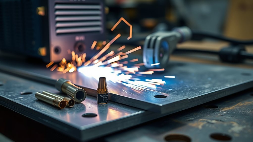
For clean cuts, you’ll match tip size to amperage: use 3/64″ tips for 0–40 A and 1/16″ tips for 40–80 A to maintain a narrow, stable plasma stream.
You’ll monitor electrode wear—especially hafnium insert pitting—and replace components when erosion enlarges the orifice or degrades arc stability.
You’ll verify consistent arc start quality by maintaining the specified fixed electrode-to-tip gap and conducting regular inspections to prevent misfires and uneven kerf.
Matching Tip Size
Tip and electrode selection determines amperage range, kerf width, and cut quality. Use data-driven tip selection and amperage matching: a 3/64” tip supports 0–40 A for thin stock and precision kerfs; a 1/16” tip serves 40–80 A for thicker sections where a wider kerf is acceptable. At 50 A, select the 1/16” tip to maintain arc stability and prevent nozzle distress.
Avoid undersizing. A tip that’s too small for the applied current overheats, distorts the orifice, and degrades cut geometry and speed. For thin materials, stay at the low end of the current range with the low-amp tip to keep the plasma column narrow and reduce dross.
Verify the torch’s specified electrode-to-tip standoff; a fixed, correct gap sustains reliable plasma formation and consistent cutting efficiency.
Electrode Wear Signs
Although your arc may still ignite, visible pitting, mushrooming, or a recessed hafnium insert on the electrode’s face signals rising resistance and imminent cut-quality loss. Treat these wear indicators as stop criteria in your electrode maintenance plan. A hafnium insert erodes predictably; when the pit exceeds manufacturer limits or the crater recesses, you’ll widen kerf, slow travel, and increase dross on steel and aluminum.
Maintain the specified gap between electrode and tip to stabilize the plasma column. Pair the correct tip size—3/64” for 0–40 A, 1/16” for 40–80 A—to prevent orifice distortion and premature replacements.
| Indicator | Impact | Action |
|---|---|---|
| Pitting | Rising arc resistance | Replace electrode |
| Mushrooming | Unstable arc focus | Replace set |
| Recessed insert | Wider kerf | Replace electrode |
| Tip distortion | Erratic stream | Match tip to amps |
| Gap drift | Inconsistent ionization | Reset spacing |
Arc Start Quality
Even before you pull the trigger, arc start quality hinges on matching the tip orifice, electrode condition, and the fixed electrode-to-tip gap to your set amperage. At 50 A, use a 1/16” tip; reserve 3/64” for 0–40 A. This alignment constrains the plasma column, improves arc stability, and preserves ignition reliability on thin stock.
Verify the torch’s specified fixed gap; deviations lower current density and widen kerf.
Inspect the electrode’s hafnium insert before each shift. Replace at the first signs of pitting or a recessed crater to prevent a distorted plasma stream and slag accumulation.
Reject worn or out-of-round tips; they cause irregular arcs and dross. Document tip/electrode hours, standardize inspection intervals, and maintain spares to sustain consistent starts and clean, repeatable cuts.
Feed Rate, Torch Height, and Technique Guidelines
Two primary controls—feed rate and torch-to-work distance—govern cut quality and heat input with a 50‑amp plasma system. To optimize cutting speed and torch stability, set torch height at 1/8 inch (≈3.2 mm). For carbon steel, target 30–60 ipm based on thickness; for aluminum, use 20–40 ipm to limit melt-back and warping. Maintain a steady traverse, constant standoff, and even hand pressure. Hold a 5–15° lead angle to eject molten material and sharpen the kerf. Monitor arc sound and kerf lag; adjust feed to keep sparks exiting 10–20° rearward, not under the plate.
| Material | Feed Rate (ipm) | Torch Angle |
|---|---|---|
| Mild Steel (thin) | 50–60 | 5–10° |
| Mild Steel (thick) | 30–45 | 10–15° |
| Aluminum (thin) | 30–40 | 5–10° |
| Aluminum (thick) | 20–30 | 10–15° |
Use short test cuts to verify dross levels and edge squareness. If dross forms on top, raise height or slow slightly; if on bottom, lower height or increase travel.
Common Mistakes That Reduce Cut Capacity
You often lose cut capacity from three preventable errors: wrong tip size, inadequate air supply, and worn consumables.
Match tip orifice to rated amperage, verify supply meets spec (e.g., ≥4.5 PSI and 6.0 CFM at the torch), and replace electrodes/nozzles before arc instability appears.
Use test cuts to validate amperage, flow, and tip condition against the material thickness before production.
Wrong Tip Size
One common limiter of cut capacity is running the wrong tip size for the set amperage. Match orifice to current per manufacturer tables; don’t guess. As a baseline, use a 3/64” tip for 0–40 A and a 1/16” tip for 40–80 A. At 50 A, a 1/16” or equivalent metric orifice maintains column stability and energy density.
If the tip’s too small, arc pressure spikes, the plasma stream distorts, and you’ll see accelerated wear, pitting, and loss of cutting efficiency. If it’s too large, the kerf widens, edge precision drops, and dross increases.
Execute routine tip maintenance: inspect orifice roundness, erosion, and spatter; replace out-of-tolerance parts. Perform tip adjustment by verifying standoff and alignment per spec. Standardize checks to protect electrodes and sustain rated capacity.
Inadequate Air Supply
Although arc current sets the energy budget, inadequate air supply often becomes the bottleneck that slashes cut capacity. Your plasma performance depends on meeting the cutter’s specified pressure and flow. For a 50 Amp unit, target at least 4.5 PSI and 6.0 CF/M at the torch while flowing.
Undersupply produces a lazy arc, dross, and incomplete kerfs; overshoot can destabilize the plume. Match the air compressor to real demand under duty cycle.
1) Verify dynamic pressure/flow: measure at the torch with air flowing; static readings are misleading.
2) Size the air compressor at 1.5–2× required CF/M to prevent pressure sag during long cuts.
3) Maintain filters, separators, and hoses; leaks and restrictions drop available volume.
4) Monitor duty cycle and temperature; continuous running indicates volume shortfall and risks overheating.
Worn Consumables
Air supply that meets spec sets the stage, but consumable condition determines whether the arc stays collimated and cuts to rated thickness.
You protect cutting precision by enforcing consumable maintenance as a controlled process. Inspect nozzles and electrodes before each shift; retire parts showing orifice ovality, nicks, or excessive electrode pitting.
Maintain the fixed electrode-to-nozzle gap per OEM spec; a collapsed or stretched gap disrupts plasma formation and reduces cut capacity on steel and aluminum.
Match tip size to amperage. Don’t run a 25‑amp tip at 60 amps; you’ll distort the orifice, overheat components, and lose efficiency.
Use only high‑quality, verified consumables. Document life hours, replace at thresholds, and torque assemblies correctly to avoid leakage paths that destabilize the arc and limit thickness.
Frequently Asked Questions
What Power Generator Size Is Needed to Run a 50 Amp Plasma Cutter?
You’ll need a generator rated 10–12 kW (continuous) to run a 50 A plasma cutter. Verify power requirements: 240 V, ~40–50 A input. Prefer inverter generator types with <5% THD, 120/240 V capability, and surge headroom.
How Does Ambient Temperature Affect Cut Quality and Thickness Capability?
Ambient temperature shifts arc stability; you’ll see degraded cut quality and reduced thickness capability in cold due to increased thermal conductivity and heat loss. In heat, duty-cycle derates; you must reduce travel speed, amperage, or accept increased dross and bevel.
Can CNC Tables Improve Thickness Capacity Compared to Handheld Cutting?
Yes. A CNC table doesn’t increase amperage, but CNC precision optimizes torch height, speed, and pierce sequencing, reducing dross and taper. You overcome handheld limitations, reliably achieving near-maximum rated thickness per manufacturer specs, consumable condition, and gas/air quality.
What Extension Cord Gauge and Length Are Safe for Full Output?
Use a 6 AWG copper, 240 V-rated cord, ≤25 ft for full 50 A output; ≤50 ft only if 4 AWG. For extension cord safety and gauge selection, you minimize voltage drop (<3%). Example: shop upgrade avoided nuisance trips.
How Do Consumable Brand Differences Impact Cut Thickness and Lifespan?
Brand differences measurably change cut thickness and lifespan: you’ll see tighter kerf and longer duty cycles with higher brand quality and superior consumable materials (copper-silver, hafnium). You’ll maintain rated thickness, reduce dross, and extend nozzle/electrode life per manufacturer specifications.
Conclusion
You want 1/2-inch clean cuts? Then stop pretending 110V will defy physics. At 50A, steel: 1/2 inch at 220V, ~1/4 inch at 110V—because arc energy isn’t a fairy tale. Aluminum: stable current, proper amperage, 1/2 inch clean when parameters match spec. Keep duty cycle, air quality (dry, consistent PSI/CFM), and consumables within standards. Maintain torch height, travel speed, and technique—or enjoy dross, bevel, and warpage. Ignore the data, and your cut quality will, too.