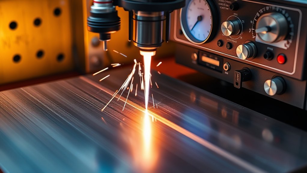
You’ll get consistent cut quality only when amperage, thickness, and travel speed align to proven benchmarks. A practical rule is about 10 amps per additional 1/8 in of steel—20 A for 1/8 in, 40 A for 1/4 in, 60 A for 1/2 in—adjusted for material condition and process gas. Misalignment widens kerf, increases bevel, and shortens consumable life. Next, you’ll map amps to thickness, then tune standoff, nozzle size, and pierce parameters for repeatable results.
Why Amperage Matters When Cutting Steel
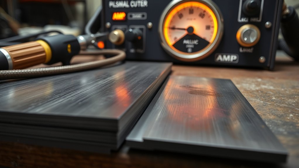
Control defines your cut quality because amperage sets the arc’s energy density, penetration, and travel speed window. You manage amperage effects to match steel thickness so the plasma jet sustains a stable kerf without overburn. A practical baseline is proportionality: increase roughly 10 amps for each additional 1/8 inch of steel. For example, 20 amps typically severs up to 1/8 inch mild steel, while 40 amps performs on 3/8 inch.
Within those bounds, higher amperage boosts cutting efficiency by allowing faster travel and minimizing dross reattachment.
However, excessive amperage elevates heat input, widening the kerf, rounding edges, and inducing distortion. You’ll see overmelting, lag lines, and a heat-affected zone that exceeds specification tolerances. Use the machine’s maximum rated amperage on thicker sections to maintain speed only if edge quality and dimensional accuracy remain within limits.
Adjust for alloy: stainless and aluminum demand tailored settings due to different thermal conductivity and melting behavior, ensuring consistent penetration and controlled edge geometry.
Reading and Using an Amperage Vs Thickness Chart
With amperage setting the arc’s energy and your cut window, the chart becomes your primary reference for matching current to thickness and maintaining specification tolerances.
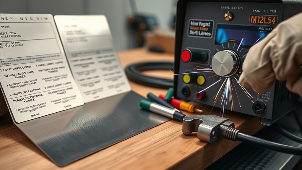
Start with chart interpretation: locate steel type, plate thickness, and the model-specific duty cycle limits. Read the recommended current, then verify nozzle rating and gas settings align. Use the baseline rule—about 20 amps for 1/8 inch and add ~10 amps per additional 1/8 inch—as a cross-check, not a substitute for the manufacturer’s table.
Start with chart interpretation: match steel, thickness, duty cycle, then confirm current, nozzle, and gas settings.
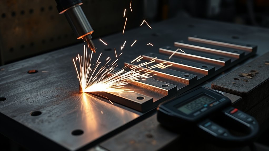
Perform amperage adjustments in small increments while monitoring kerf profile, dross formation, and travel speed. Higher amperage increases cutting speed but risks overmelting and edge rounding; reduce current if you see a wide kerf or top-edge wash.
For 3/8 inch, expect guidance near 40 amps; for 1/2 inch, around 50 amps—confirm against your model’s chart. Recheck settings when switching steel grades; alloy and coatings can shift ideal current. Document results to refine future setup.
Recommended Amp Settings for Common Steel Thicknesses
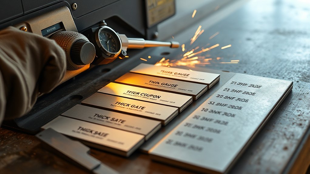
Although every machine and torch kit has its own limits, you can set a reliable baseline for mild steel by matching amperage to thickness in 1/8-inch steps. Use these amperage settings across common thickness ranges to maintain kerf control, minimal dross, and consistent edge quality. Start at 20 A for 1/8 in, then add roughly 10 A for each additional 1/8 in of section.
| Thickness (in) | Recommended Amps |
|---|---|
| 1/8 | 20 |
| 3/16 | 30 |
| 1/4 | 40 |
| 3/8 | 50 |
| 1/2 | 60 |
Apply this baseline as your primary setup before fine-tuning. At 40 A on 1/4 in, you’ll typically achieve ideal arc stability and clean separation. Moving to 3/8 in, 50 A helps avoid lag lines and heat distortion while preserving cut geometry. For 1/2 in, 60 A increases energy density to sustain the arc column through the full thickness without over-widening the kerf. Validate with test coupons, verify consumable condition, and confirm duty cycle margins.
Balancing Cut Speed, Amperage, and Quality
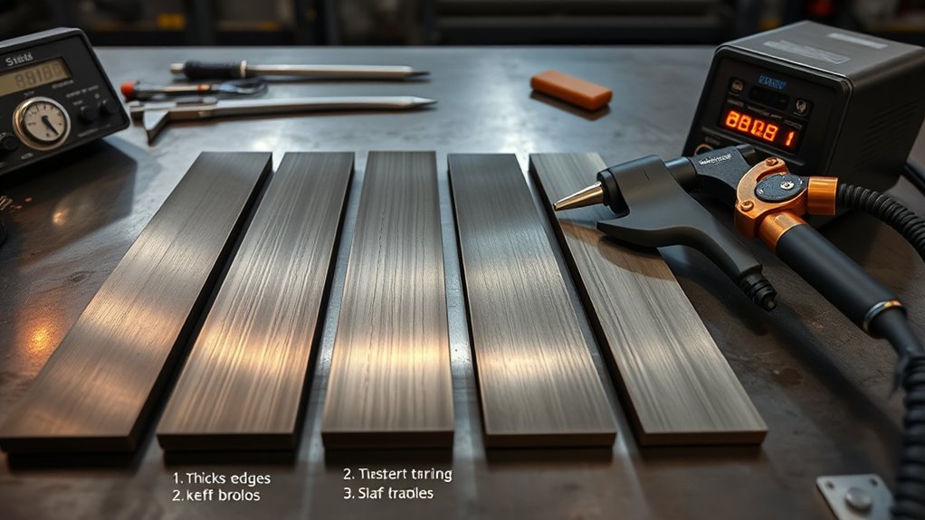
Even as thickness changes, you’ll balance amperage and travel speed to hold kerf width, edge angle, and dross within spec. Use the baseline: add about 10 amps per additional 1/8 inch. For reference, about 20 A suits 1/8 inch steel; around 40 A is effective at 3/8 inch. Validate with test coupons and record results to standardize your cutting techniques.
Match current to speed. For manual cuts, target 10–15 IPM; with automation, you can run faster if the arc stays stable and the edge remains square. If you push amperage without increasing thickness, you’ll raise velocity but risk overmelting and distortion.
If you go too slow at any setting, heat input spikes and warping increases, so prioritize heat management.
Watch indicators: a trailing arc plume and heavy bottom dross signal slow travel; bevel and top spatter indicate excessive speed. Adjust in small increments, maintaining continuous motion to keep quality within tolerance.
Nozzle Orifice Size, Kerf Width, and Gas Pressure
Because nozzle geometry governs arc shape and energy density, you must match orifice size, amperage, and gas pressure to control kerf width and cut quality. Larger orifices widen the arc and kerf; smaller orifices concentrate energy for a narrower, cleaner slot. Use nozzle adjustments to align tip size with current: e.g., a 30 A tip typically uses a 0.8 mm (0.030 in) orifice at 55–60 psi. Maintain gas consistency to stabilize the arc and minimize dross.
| Tip/Amperage | Orifice Size | Typical Gas Pressure |
|---|---|---|
| 30 A | 0.8 mm (0.030 in) | 55–60 psi |
| 40 A | ~0.9 mm | 60–65 psi |
| 50 A | ~1.0 mm | 65–70 psi |
| 60 A | ~1.1 mm | 70–75 psi |
| 70–80 A | ~1.2 mm | 75–80 psi |
Kerf varies by material; polished aluminum often cuts narrower than mild steel at the same settings. Stay within manufacturer pressure bands (typically 50–80 psi) and verify flow under load. Proper pressure prevents arc wander, reduces dross, and preserves nozzle life.
Standoff, Voltage, and Bevel Control
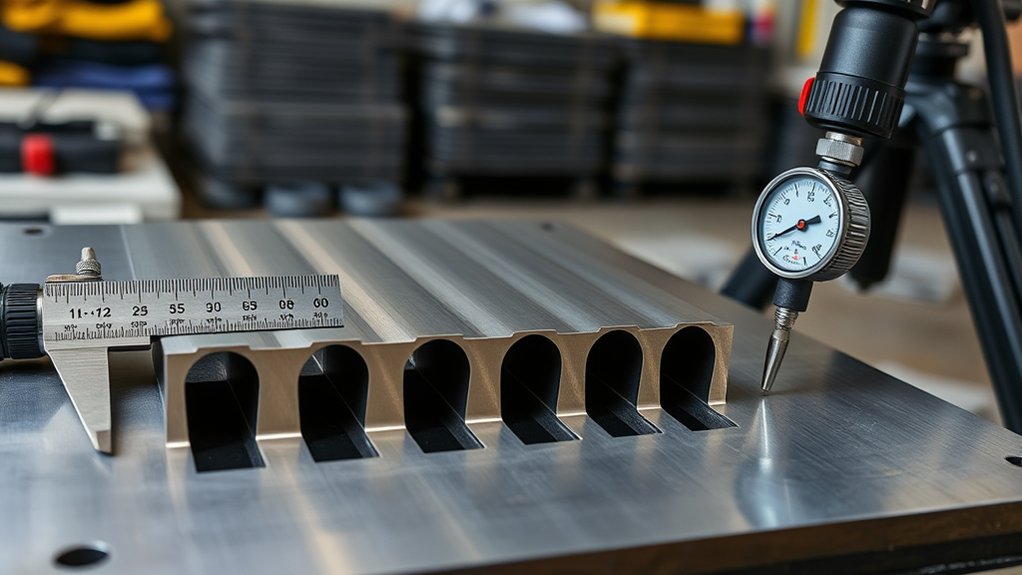
With nozzle size, amperage, and gas pressure set, you must control torch standoff and arc voltage to keep kerf geometry and bevel within tolerance. Treat standoff adjustment and voltage regulation as coupled variables: arc voltage rises with distance, increasing bevel angle and kerf variability.
Hold a consistent torch-to-work distance to stabilize voltage and mitigate heat-induced warpage. Set voltage relative to plate thickness; too low yields a wide, wandering kerf and dross. Too high steepens bevel and can overheat edges.
Maintain constant torch height to stabilize voltage; set voltage to thickness to avoid dross, wandering kerf, and overheated bevels.
For thicker steel, incrementally increase voltage while maintaining a fixed operating standoff to sustain arc stiffness and straightness. Monitor surfaces for bumps and scale; even small height excursions shift voltage and bevel.
Use height control to track the work and correct standoff in real time. After pierce, shift to a steady cutting height and lock voltage to the target window. Validate by measuring bevel angle and kerf width; adjust standoff or voltage to bring both within spec.
Pierce Height, Pierce Delay, and Consumable Life
Although cutting height governs kerf quality, you’ll protect consumables and stabilize starts by setting pierce height and delay to spec. Use a pierce height at 1.5–2.0× the cutting height to shield the nozzle from splashback and high-velocity ejecta. That spacing is foundational to pierce optimization techniques and measurable consumable wear reduction.
For thin steel, target a pierce delay of 0.19–0.24 s so the molten pit fully forms before motion. Scale delay with thickness; thicker plate requires longer dwell to clear the jet path without double-arcing.
After pierce, descend to cutting height before X–Y motion. Verify arc transfer timing in your CNC to prevent premature motion.
Audit results by tracking divot size, dross at lead-ins, and nozzle orifice erosion. If you see crater spatter or tip burn, increase height or delay incrementally. If lead-in elongates or top-edge rounds, reduce delay.
Continual monitoring and adjustment extend consumable life and lower replacement cost.
Safety and Setup Best Practices for Thin to Thick Steel Cuts
Set pierce height and delay to spec, then prepare the workstation so the cut stays controlled and repeatable from thin sheet to heavy plate.
Don’t start until you’ve put on safety equipment: heavy-duty gloves, safety glasses, and reinforced boots. Confirm grounding, ventilation, and a clear egress path for hot parts.
Suit up: gloves, safety glasses, reinforced boots. Verify grounding, ventilation, and a clear egress for hot parts.
Calibrate amperage to thickness: 20 A up to 1/8 in, then add 10 A per additional 1/8 in. Document these setpoints on your job traveler.
Use metal securing appropriate to gauge—magnets and low-heat clamps for thin sheet; rigid, distributed clamping for plate—to prevent sliding and heat-induced warping.
Maintain a constant standoff with a height control system or gauge. This stabilizes arc voltage and limits bevel variability due to surface irregularities.
Align lead-ins/lead-outs and apply kerf compensation so parts don’t drop into the kerf. Verify nozzle, shield, and electrode condition; replace as needed to keep edge angularity and dross within tolerance.
Conduct a dry run before striking arc.
Frequently Asked Questions
How Does Ambient Temperature or Humidity Affect Amperage Selection?
You adjust amperage minimally for ambient conditions. Colder air increases density and cooling, demanding slightly higher current; heat/humidity reduce cooling, allowing minor reductions. Prioritize metal properties, duty cycle, and cut quality; validate with test coupons and manufacturer specifications before production.
What Duty Cycle Considerations Impact Long Continuous Cuts?
You size amperage to respect duty cycle during continuous operation. Use rated current at 40°C, derate for hotter shops, monitor thermal limits, and schedule pauses. Exceeding duty cycle overheats components, triggers protective shutdowns, degrades consumables, and reduces cut quality and productivity.
How Do Generator Power Variations Influence Cut Consistency?
Generator stability directly affects arc quality; power fluctuations cause voltage sag, inconsistent amperage, and erratic kerf. You’ll mitigate with inverter-compatible units, ≥20% headroom, low THD (<5%), proper grounding, rated cords, and line-conditioning (AVR/UPS) to maintain consistent cut speed, penetration, and dross control.
Are There Differences for Painted, Galvanized, or Rusted Steel Surfaces?
Yes. You face three skins: paint, zinc, and rust—each distorts arc stability and kerf. You’ll prioritize surface preparation: targeted paint removal, avoiding zinc fumes, de-scaling rust. Expect higher dross, slower travel, stricter ventilation, and calibrated consumable inspection intervals.
How Do CNC Vs Handheld Torches Change Amperage Choices?
You’ll select higher amperage for CNC torches due to faster, consistent speeds and CNC advantages in duty cycle. You’ll run slightly lower amperage for handheld torches, compensating Handheld limitations: slower travel, variable standoff, increased dross risk.
Conclusion
You’ve now got the amperage-to-thickness playbook to make your plasma arc sing, not sputter. Treat 10 amps per 1/8 inch as your north star, then fine-tune cut speed, standoff, and gas pressure to keep kerf narrow and edges square. Lock in pierce height and delay to save consumables, and match nozzle size to current like gears in a gearbox. With standards-driven settings and disciplined setup, you’ll slice steel cleanly, repeatedly, and safely—like a laser through midnight fog.