Most operators don’t realize high‑carbon steel hardens rapidly if your heat input drifts outside a narrow window. You’ll set 30–50 A based on thickness, hold 120–150 V, and match air pressure to the torch chart to avoid dross and microcracking. Keep standoff consistent, use faster cut speeds to shrink HAZ, and prep surfaces clean and dry. With proper consumable care and safety controls, you can achieve repeatable edges—if you fine‑tune these variables next.
Understanding High-Carbon Steel and Its Cutting Challenges
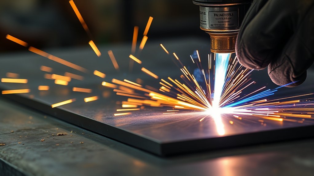
Although plasma cutting seems straightforward, high‑carbon steel (about 0.6–1.4% C) demands tighter control because its higher hardness and brittleness amplify heat‑related risks. You’re dealing with elevated carbon content, so brittleness issues and stress induction rise as thermal gradients steepen.
High‑carbon steel demands tighter plasma‑cutting control as hardness and brittleness magnify heat‑related risks.
Prioritize heat management: set amperage just high enough to sustain the arc and increase travel speed to shrink the HAZ, improving cutting efficiency while limiting warping effects.
Maintain a consistent standoff distance to stabilize arc energy density and reduce defects. Watch kerf color and slag behavior; both indicate excessive heat or poor gas flow that drives dross formation.
For thicker sections, apply preheating techniques (typically 100–260°C, based on section thickness) to slow cooling, mitigate cracking, and balance microstructural transformation.
Use straight, continuous motion to minimize dwell, then allow controlled cooling; forced quenching spikes hardness and residual stresses.
Validate parameters with test coupons, recording HAZ width, edge hardness, and distortion to confirm stable, repeatable cut quality.
Selecting the Right Plasma Cutter and Consumables
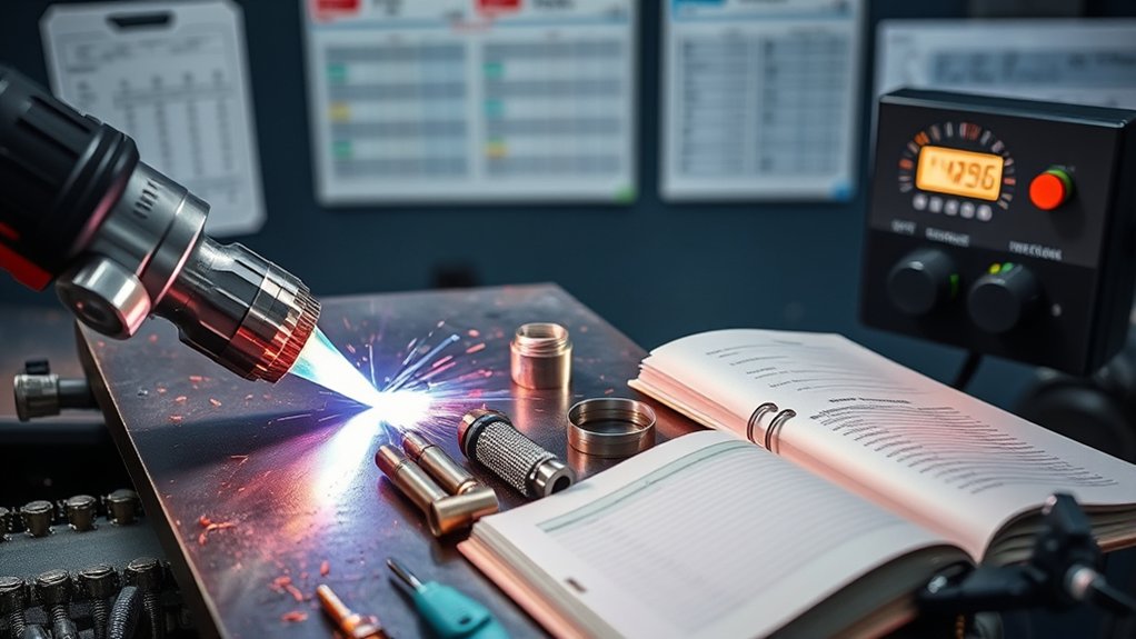
Two specs drive your plasma-cutter choice for high‑carbon steel: usable amperage for your target thickness and a duty cycle that sustains it.
Match output power to material: for example, ~40–45 A handles 1/4 in (6 mm), 60–65 A reaches 3/8 in (10 mm), and 80–100 A tackles 1/2 in (12–13 mm). For continuous shop work, target a 60–100% duty cycle at the amperage you’ll actually cut, not the machine’s peak.
Prioritize plasma cutter selection with solid thermal management, clean, dry air handling, and stable arc initiation.
Choose torches compatible with high-wear consumable types engineered for harder alloys—heat-resistant electrodes (e.g., hafnium inserts), robust nozzles/tips, and shields designed to maintain a constricted, stable jet.
Inspect tip orifice, electrode pit depth, and shield integrity at set intervals; replace on spec to prevent kerf widening, dross, and unnecessary HAZ growth.
Use machines with adjustable amperage and voltage windows to balance cut speed, quality, and distortion while keeping safety margins.
Dialing In Amperage, Voltage, and Air Pressure
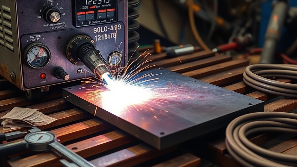
You’ll match amps to thickness—typically 30–50 A for high‑carbon steel—to avoid dross and maintain cut integrity.
Set voltage to maintain a stable arc at your standoff (1/16–1/8 in), usually 120–150 V, and verify with clean, unworn consumables.
Hold air pressure at 60–70 psi to stabilize the arc and protect cut quality and operator safety.
Match Amps to Thickness
Start by matching output to the material: target roughly 1 amp per 0.001 in of high‑carbon steel thickness, then fine‑tune while watching cut quality and HAZ.
Use incremental amperage adjustments to track how kerf width, dross, and spark angle respond to thickness variations. For example, 0.375 in plate starts near 375 A; if the arc gouges or HAZ grows, step down 5–10 A and re‑evaluate.
Keep voltage within 70–100 V and air at 60–80 PSI to stabilize the arc and purge molten metal.
Confirm sparks exit 10–20 degrees from the bottom; if they spray upward, increase amperage or reduce travel speed. If sparks trail excessively, decrease amps to curb heat input.
Prioritize minimal HAZ, straight kerf walls, and fully severed edges without top‑side dross.
Set Voltage via Standoff
Why does voltage seem slippery to pin down? In air plasma, torch height controls arc length, and arc length defines arc voltage. You effectively perform voltage adjustment by holding a precise standoff distance. For high-carbon steel, lock in 1/16–1/8 inch cutting height; use a height control if available. Set pierce height at 1.5–2× cutting height to protect consumables, then drop to the cutting standoff.
Match amperage to thickness (typically 50–100 A) and set air at 60–80 PSI dry, stable flow.
Verify voltage via cut behavior: correct standoff yields narrow kerf, straight dross, and minimal bevel. Too high standoff (high voltage) produces lag lines and top-edge rounding; too low (low voltage) causes double-arcing and spatter.
Maintain 20–30 ipm travel speed to limit HAZ and stabilize arc voltage.
Cut Speed, Standoff, and Pierce Height Settings
You’ll lock in ideal cut speed at roughly 40–60 IPM, adjusting for thickness and amperage to control dross and keep the HAZ tight.
Maintain a consistent torch standoff of 1/16–1/8 inch to stabilize arc length and prevent excess heat input or edge wash.
Set pierce height at 1.5–2× cutting height to protect consumables and guarantee clean penetration before lowering to the cut height.
Optimal Cut Speed
Although material and machine vary, dial in high-carbon steel by targeting 40–80 IPM cut speed, a 1/16–1/8 in standoff, and a pierce height set to 1.5–2× the cutting height.
Start at mid-range speed, then adjust based on kerf quality and slag. Let material properties guide you: higher carbon and thicker sections favor the lower half of the range; thinner plate and fine-feature cutting techniques can run faster.
Watch arc lag and dross: heavy bottom dross and a wide HAZ indicate speed is too slow; top spatter and bevel suggest you’re too fast.
Pair speed with current—if you increase speed, reduce amperage to limit heat input and distortion. Validate on scrap, confirming smooth kerf, minimal bevel, and stable arc initiation.
Wear PPE and shield bystanders.
Consistent Torch Standoff
Even with a well-chosen cut speed, you won’t get repeatable results unless the torch holds a steady standoff. Keep torch height between 1/16 and 1/8 inch to control arc stability, edge angularity, and the heat-affected zone.
Too low increases kerf bevel, dross, and plate gouging; too high widens the arc, overheats edges, and enlarges HAZ.
Use arc-voltage control or a mechanical follower to hold standoff as sheets warp. Watch spark ejection: a vertical stream from the bottom indicates correct arc length and speed.
If sparks trail backward, increase travel speed or reduce height slightly; if they spray forward, slow down or verify amperage.
Balance higher cutting speeds with adequate current to avoid distortion.
Audit standoff frequently, especially over heat crowns and mill scale.
Correct Pierce Height
Why start the cut any other way than with the right pierce height? Set pierce height at 1.5–2.0 times the cutting height to shield the nozzle and shield cap from blowback and prevent molten pit formation.
Then shift to the cutting standoff—hold 1/16–1/8 inch—to stabilize arc voltage, narrow the HAZ, and improve cutting efficiency.
On high‑carbon steel, coordinate pierce height with amperage and cut speed. Too low and you’ll crater the plate, overheat consumables, and increase dross; too high and the arc wanders, delaying penetration.
Begin the pierce at a 40° lead angle, rotate to 90° as it breaks through, then accelerate to programmed speed. Verify pierce delay just clears slag.
Log arc voltage, height, and speed to replicate best results safely.
Managing and Minimizing the Heat-Affected Zone
Because high-carbon steel is sensitive to thermal cycles, managing the heat-affected zone (HAZ) starts with controlling total heat input: set amperage, voltage, and cutting speed to match thickness and grade, then verify by observing kerf width, arc lag, and edge coloration.
Faster speeds decrease dwell time and limit heat transfer into adjacent material; target a narrow kerf, minimal arc lag, and straw-to-blue edge colors without excessive oxidation. If edges show dark blue/black bands, reduce amperage or increase speed.
Use short, continuous cuts to limit soak. Maintain correct standoff to stabilize the arc column and reduce conductive losses. Log parameters by thickness and steel grade, and adjust live when you see widening kerf or increasing dross.
After the cut, apply appropriate cooling techniques: forced air for thin sections, controlled water quenching only when metallurgy allows, and clamped heat sinks for thick parts.
Always avoid rapid quench on highly hardened zones to prevent cracking.
Surface Preparation and Workholding for Clean Cuts
Before you strike an arc on high‑carbon steel, treat surface prep and workholding as process controls that directly affect cut quality, electrical stability, and HAZ.
Execute disciplined surface preparation: remove rust, paint, oil, and mill scale within the clamp path and cut zone. Use solvent wipe, then mechanically abrade to bright metal; verify with a continuity check (<0.1 Ω from clamp to cut start). Attach the ground clamp to bare steel, tighten fully, and position it within inches of the cut line to reduce circuit resistance and voltage drop.
Stabilize the work with proven workholding techniques. Use rigid clamps or magnetic fixturing rated for plasma environments; avoid heat‑softening polymers.
Confirm the support table is flat; shim or replace slats showing warpage >1 mm over 300 mm. Re-inspect after heat cycles. Prevent movement with at least two opposing clamps and a positive stop.
Maintain clean, conductive contact surfaces, and keep cable paths short, untangled, and undamaged to preserve current density and minimize HAZ.
Technique Tips: Starts, Stops, and Edge Quality
With surfaces clean, clamped, and electrically solid, focus on torch handling to control starts, stops, and edge quality.
Use edge-start techniques: fire the arc at the plate’s edge, then shift into the line to achieve immediate penetration and reduce consumable stress.
Hold a consistent 1/16–1/8 in standoff; verify with a gauge or drag shield. Maintain perpendicularity to minimize bevel, and adjust travel speed to thickness—faster speeds typically produce a narrower kerf, less dross, and a smoother edge.
Monitor the kerf stream: sparks exiting 10–20° below the plate confirm correct speed; a vertical stream indicates too slow, causing dross.
For stop techniques, ramp out by slightly angling the torch upward at the end to clear the kerf and prevent slag tails. Avoid pausing in the cut path; if a pause is required, backtrack slightly before exiting.
Log settings (amperage, speed, standoff) with thickness to replicate edge quality safely.
Consumable Care and Replacement Intervals
Although plasma systems tolerate some abuse, high-carbon steel magnifies any lapse in consumable care, so inspect tips and electrodes at the start of each shift and after long cuts.
Use a gauge or visual check: replace tips with irregular or enlarged orifices, spatter buildup, or tapering; replace electrodes showing pitting or truncated hafnium inserts. To preserve cut quality and minimize dross, replace tips and electrodes as a matched set; staggered wear degrades arc stability and increases kerf wander.
Build maintenance schedules around amperage, duty cycle, and pierce count. Track arc-on minutes and pierces per set to baseline consumable longevity, then adjust by ±20% when cutting high-carbon steel.
Avoid over-tightening the retaining cup; finger-tight is sufficient to prevent air leakage without distorting components. Control moisture with desiccant dryers and drain compressors daily; moisture accelerates double-arcing and cratered electrodes.
Standardize technique: correct standoff, perpendicular torch, and steady travel speed reduce thermal loading and extend life.
Safety Practices and Post-Cut Finishing Steps
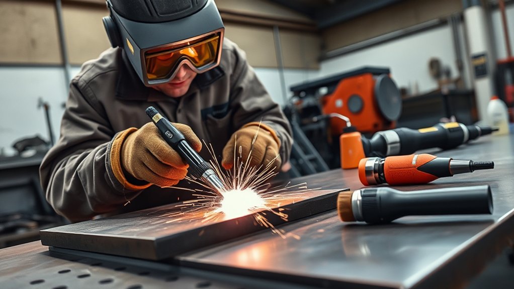
Even when the cut path is dialed in, high‑carbon steel demands disciplined safety and finishing. Wear full safety equipment: FR clothing (ASTM F1506 or equivalent), leather gloves, and a welding helmet with shade 8–12 for plasma arcs. Verify torch integrity—shield cup, tip, and electrode—before power-up; replace worn parts to prevent double-arcing and spatter. Keep a dry, uncluttered area; remove vapors and combustibles. Ground the work securely and route cables to avoid snags.
Allow parts to air-cool to ambient; don’t quench—rapid cooling elevates residual stress and risks microcracking. For post cut maintenance, de-dross with a wire brush or 36–60 grit flap wheel; maintain edge squareness for tight tolerance fits. Log consumable hours per the manufacturer and replace on schedule to stabilize amperage and arc constriction.
| Step | Metric/Specification |
|---|---|
| Helmet lens | Shade 8–12 (arc brightness dependent) |
| Electrode wear limit | < 1 mm pit depth before replacement |
| Edge finishing | 36–60 grit; ≤ 0.2 mm burr height target |
Frequently Asked Questions
Can Plasma Cutting Affect High-Carbon Steel’s Weldability Afterward?
Yes. You’ll alter weldability via a hardened heat affected zone and carbide precipitation. Mitigate by controlling amperage, standoff, and travel speed, then grind 0.5–1.0 mm, preheat 150–250°C, and post-heat/temper. Verify cut surface durability with hardness checks.
What Post-Cut Heat Treatment Restores Hardness or Toughness?
Use normalizing at 800–900°C with air cool for toughness, or quench-and-temper for hardness restoration. Apply post cut annealing (650–700°C) to reduce HAZ stresses. Control soak times by thickness, verify with hardness testing, and follow PPE/temperature-interlock safety.
How Do Ambient Temperature or Humidity Impact Cut Quality?
Ambient temperature and humidity directly affect cut quality via arc stability and condensation risk. studies show 10°C drops can increase dross 15%. You mitigate environmental factors by preheating work, drying air supply (<3 g/kg), shielding wind, and maintaining PPE.
Are There Certifications or Standards for Cut Edge Integrity?
Yes. You follow cutting standards like ISO 9013 (thermal cutting), ISO 13920/EN 1090 tolerances, AWS D1.1/D1.3 acceptance, and API/ASME specs. They define edge quality, roughness, bevel, HAZ limits, microcracks, and inspection methods (visual, profilometry, PT/MT).
Can CNC Nesting Strategies Reduce Distortion on Small Parts?
Absolutely—like armor for your layout—you can use CNC nesting to achieve distortion reduction. You’ll stagger pierces, add micro-tabs, balance heat paths, maintain edge distance, optimize lead-ins/outs, and sequence cuts to minimize residual stress and prevent thermal warping.
Conclusion
You’ve now charmed high-carbon steel with cold, data-driven romance: 30–50 A, 120–150 V, air clean and dry, cut speeds brisk, standoff steady, pierces precise. You’ll prep surfaces like a lab tech, babysit consumables, and treat HAZ like a contagious disease—because it is, thermally. Keep PPE on, ground solid, cords intact, and fire watch active. Ignore this and you’ll get dross stalactites, cratered edges, and a lecture from physics. Follow it and you’ll get surgical kerfs every time.