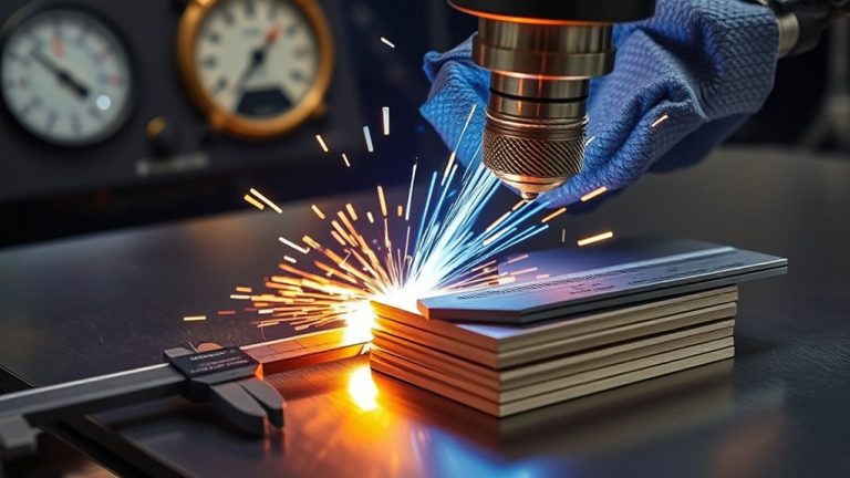
You match plasma amperage, travel speed (IPM), and air pressure to steel thickness, or you risk taper, dross, and torch damage. Start thin gauges near 0.35 MPa (55 PSI) and low amps; step up toward ~50 A as you approach 1/2 inch, reducing IPM accordingly. Set standoff and pierce height precisely, verify duty cycle, and calibrate kerf in your CAM. Want a fast, safe baseline by thickness, cutter class, and air demand?
How Thickness Dictates Amps, Speed, and Air
As steel gets thicker, you must scale amperage, travel speed, and air pressure to maintain a stable arc and clean kerf.
Match output to material properties: thin 24GA mild steel starts near 0.35 amps and ~55 IPM; as thickness rises, increase current and reduce IPM. For 1/2 inch, target roughly 50 amps and slow near 1.2 IPM.
Match output to material: start near 0.35 amps at 24GA; 1/2 inch needs ~50 amps at ~1.2 IPM.
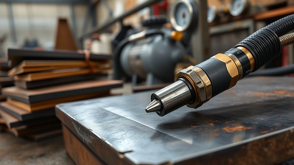
Use cutting techniques that keep arc energy density consistent: raise air pressure from about 0.35 MPa (55 PSI) on thin sheet upward as thickness grows to clear dross and cool consumables.
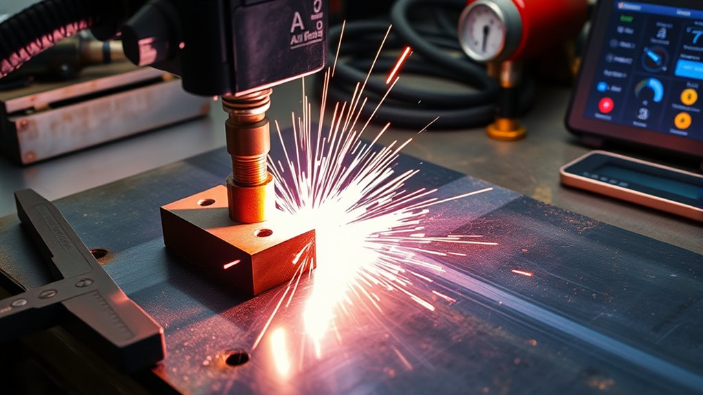
Set pierce height at 1.5–2.0× cut height; with a typical 0.125-inch cut height on mild steel, pierce at 0.188–0.25 inch.
Apply a pierce delay of 0.19–0.24 seconds to prevent blowback and nozzle damage. Verify kerf quality in the first inch; if lag lines trail excessively, increase amps or reduce speed.
Maintain dry, filtered air and ground securely before cutting.
Steel Thickness-to-Amperage Reference Chart
Use this thickness-to-amperage chart to set a safe, effective baseline before fine-tuning. Match material thickness to initial current, then validate arc stability, kerf width, and dross.
For mild steel, start near 0.35 A on 24 ga, increasing progressively; by 14 ga, target 20–25 A for clean severance. Apply the same baseline for stainless and aluminum of comparable thickness, then trim current per heat input and edge quality.
Respect material considerations: conductivity, surface coatings, and joint design affect amperage demand.
Procedure:
- Select amperage from thickness row.
- Set air to ~0.35 MPa (55 PSI) for thin sheet; scale higher as thickness rises.
- Set pierce height 1.5–2× cutting height to protect consumables.
- Test cut; adjust current in small increments to eliminate lag or top bevel.
Indicators:
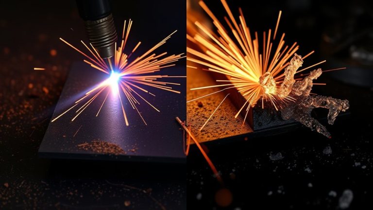
- Too low amps: arc lag, heavy bottom dross.
- Too high amps: wide kerf, top spatter, accelerated wear.
Integrate cutting techniques (torch angle, standoff control) to lock in repeatable results.
Recommended IPM by Thickness and Cutter Class
Before you press go, tie feed rate (IPM) directly to thickness and cutter class so the arc stays stable and the kerf stays narrow. Use these baselines, then verify by test coupons and torch height control.
Before you press go, tie IPM to thickness and cutter class for stable arcs and narrow kerfs.
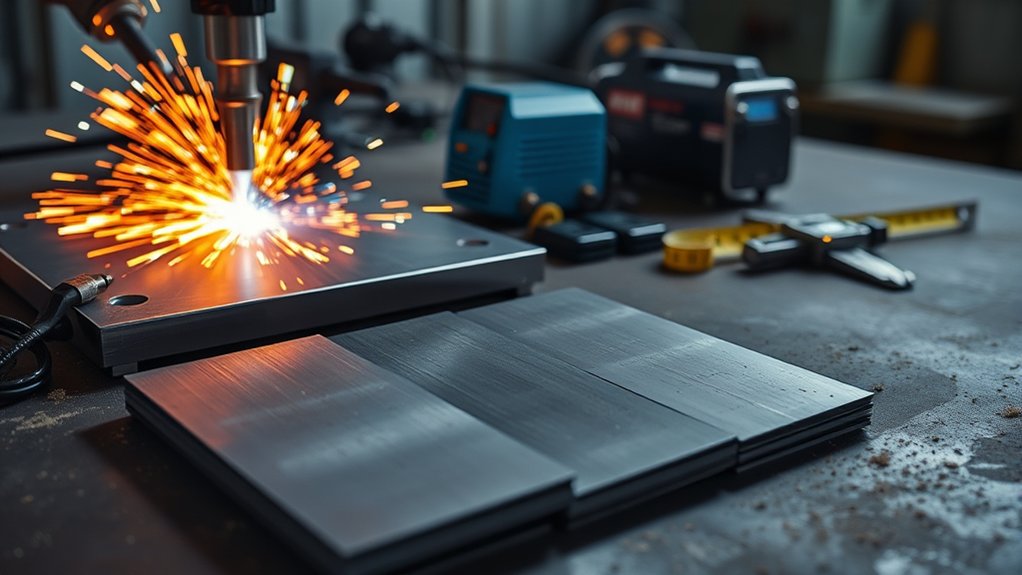
For light-duty cutters on 24 ga mild steel, target ~55 IPM at ~0.35 A; maintain a tight standoff to avoid top dross. In the hobby/entry class on 1/8 in, run ~20 IPM at ~30 A; watch the lead-out to prevent trailing slag. Mid-tier machines on 1/4 in perform at ~10 IPM and ~40 A; if you see lag lines tilt, increase IPM slightly. Heavy-duty cutters on 1/2 in hold quality at ~5 IPM with 50–60 A; confirm full pierce before motion.
Apply consistent cutting techniques: square torch, correct height, steady acceleration, and clean work clamp. Pair feed rates with nozzle size and duty cycle.
Prioritize equipment maintenance—dry consumables, clean nozzles, solid grounds—so programmed IPM translates into predictable, code-compliant cuts.
Air Supply and Pressure Requirements by Cut Range
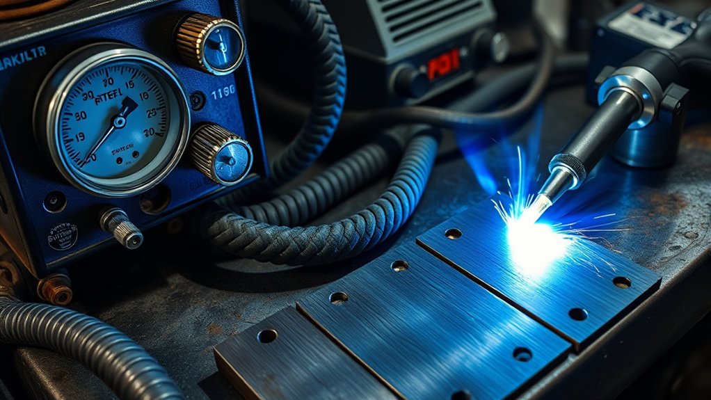
Two fundamentals govern plasma cut quality across thickness ranges: clean, dry air and correct line pressure at the torch. Treat air quality and pressure regulation as critical control variables.
Start thin mild steel at 0.35 MPa (55 PSI); verify at the torch after flow to account for line drop. As thickness or material hardness increases, step pressure up per your machine’s cutting chart, then validate by monitoring arc stability and dross. Use the regulator for fine adjustments only—don’t compensate for poor filtration with extra pressure.
Maintain dry air with a dryer and particulate/coalescing filters; moisture degrades arc density, slows cuts, and erodes consumables.
Log pressure before each shift and after major duty cycles. When charts specify a range, begin midrange, test cut, then adjust ±3–7 PSI to optimize speed and kerf integrity. Higher pressure typically improves speed and cut quality on thicker sections, but avoid over-pressurizing; excessive flow cools the arc and widens kerf.
Always lock regulators and leak-check lines.
Setup Tips: Standoff, Pierce Height, and Kerf Compensation
Although machine settings vary by torch and material, you’ll get consistent, square edges by locking in three fundamentals: standoff, pierce height/delay, and kerf compensation.
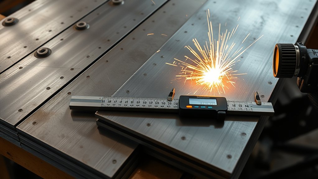
Respect standoff importance: hold a constant torch-to-work distance to stabilize arc column, minimize bevel, and protect consumables. Use a torch height control or a fixed spacer; verify with a feeler gauge before each run.
Maintain consistent standoff to stabilize the arc, reduce bevel, and protect consumables; verify with a feeler gauge.
Set pierce height at 1.5–2× the steady-state cut height to shield the nozzle from blowback, then index down to cut height after the pierce delay expires.
Program pierce delay long enough for the puddle to clear; too short causes dross and tip damage, too long increases warpage. Validate by test coupons and observe arc-through before motion.
Apply kerf compensation in CAM/CNC: offset toolpaths by measured kerf width, inside for holes, outside for profiles.
Reference kerf charts per metal and thickness, then fine-tune with cut samples to reduce waste and hold tolerance.
Wear PPE.
Frequently Asked Questions
How Do Consumable Wear and Nozzle Size Affect Cut Quality Over Time?
Consumable wear enlarges or deforms the orifice, degrading cut quality, arc stability, and kerf precision. Oversized nozzles overheat and dross increases. You schedule nozzle maintenance, log pierce counts, verify orifice diameter with gauges, and replace components proactively to maintain safety.
Can Plasma Cutters Handle Galvanized or Painted Steel Safely?
Yes, you can, but you must manage fumes. Coincidentally, galvanized steel and painted surfaces both release toxic gases. You’ll use local exhaust, downdraft, respirator, pre-grinding, and proper grounding. Log ventilation CFM, verify PPE ratings, and monitor CO/CO2/ozone.
What Shop Power Requirements Are Needed for Higher-Amperage Plasma Cutters?
You’ll need a dedicated power supply: typically 240V single-phase for 40–65A units, 480V three-phase for 80–125A. Verify amperage requirements (50–100A breakers), use appropriately rated wiring, grounded receptacles, clean earth, surge protection, and GFCI where code-required.
How Do Duty Cycle Ratings Limit Continuous Cutting on Thick Plate?
Measure twice, cut once: Duty cycle ratings cap continuous operation; you must pause when the timer hits its percentage. At thick-plate amperage, heat spikes, triggering thermal protection. Program intervals, monitor temps, and enforce cooldowns to prevent torch, lead, and compressor damage.
What Ventilation or Fume Extraction Is Recommended for Indoor Plasma Cutting?
Use local exhaust: a downdraft table or high-vacuum fume extraction torch, 250–500 CFM at source, HEPA + activated carbon. Supplement with cross-ventilation, maintain negative pressure, monitor CO/particulates, guarantee make-up air, and follow indoor safety and OSHA/NIOSH guidelines.
Conclusion
As you dial amps to match thickness, it’s no accident your IPM and air pressure land in sync—coincidence favors the prepared. You’ll set 0.35 MPa, verify standoff, pierce height, and kerf, then watch a clean arc trace your code’s toolpath. Lockout-tagout, check consumables, test scrap, confirm ground, and log parameters. When steel, current, and air converge exactly, you don’t just cut—you reproduce a safe, repeatable spec. That’s precision by design, not luck.