Like a machinist’s cheat sheet, you’ll match plasma tip orifice to amperage, air pressure, and metal thickness to control kerf, speed, and cut quality. You’ll pair a 0.6 mm tip at 15–20 A for thin stock, step to 1.0 mm at 41–50 A for thicker sections, and adjust standoff and pierce height to stabilize arc voltage. With charts linking amps to thickness, pressure, and offsets, precision hinges on one choice you haven’t made yet.
How Tip Orifice Size Relates to Amperage and Kerf
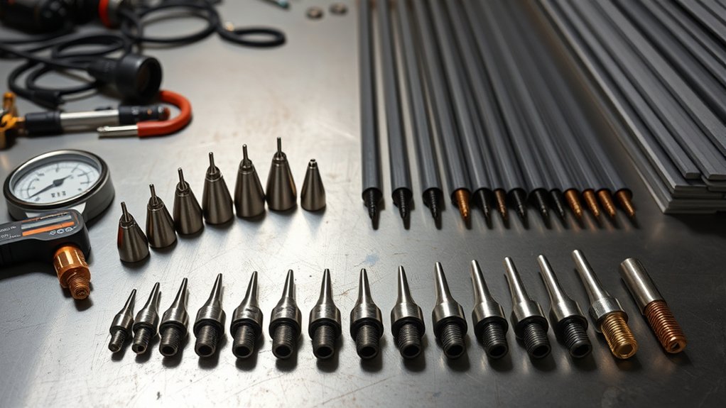
Precision starts at the orifice. You control arc energy by matching tip diameter to output current. The tip size influence is quantifiable: a 1.0 mm orifice typically stabilizes around 20 amps for thin material cutting, while a 0.6 mm, labeled as a 20-amp tip, runs cleanly at 15–20 amps.
Precision starts at the orifice—match tip diameter to current to control arc energy.
A 1.0 mm, rated 50 amps, holds arc integrity at 41–50 amps. That amperage correlation aligns constriction, gas velocity, and current density so the plasma jet remains coherent and efficient.
Kerf follows the orifice but isn’t identical. Expect the kerf to be slightly wider than the tip: a 0.6 mm orifice yields a marginally wider cut due to arc flare and heat-affected material removal.
Your travel speed tightens or widens that kerf. Move too slowly and the kerf increases; hold ideal speed to minimize width and dross. Properly pairing tip size and amperage produces a narrow, consistent kerf and reduces waste.
Recommended Tip Sizes, Amperage, and Air Pressure
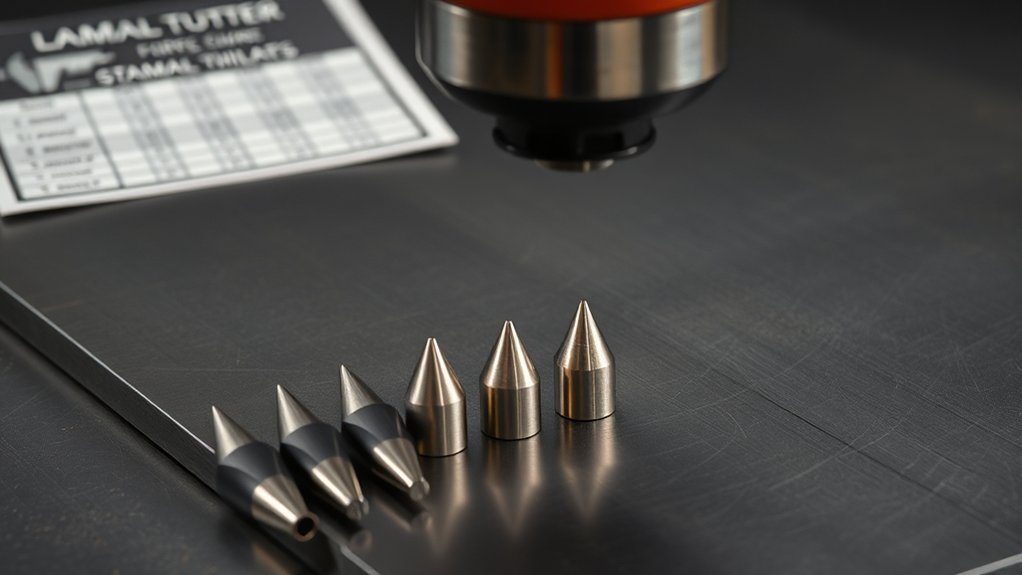
Start with the spec, then dial it in: match tip orifice to output current and set air pressure within a tight window to maintain arc constriction and cut quality. For reliable results, base tip selection on the orifice size and the machine’s rated output, then verify with pressure adjustments at the regulator while monitoring cut face and dross.
Use these baseline ranges:
- 20A tip (0.6 mm/.025): 15–20 A, 50–55 psi
- 30A tip (0.8 mm/.030): 21–30 A, 55–60 psi
- 40A tip (0.9 mm/.035): 31–40 A, 65–70 psi
- 50A tip (1.0 mm/.040): 41–50 A, 65–75 psi
- 60A tip (1.1 mm/.044): 51–60 A, 65–75 psi
| Tip (A) | Current Window (A) | Air Pressure (psi) |
|---|---|---|
| 20 | 15–20 | 50–55 |
| 40 | 31–40 | 65–70 |
| 60 | 51–60 | 65–75 |
Set amperage first to stay within the nozzle’s thermal capacity, then trim pressure 2–3 psi at a time. Too low loses arc constriction; too high widens kerf and erodes tips. Validate by checking perpendicular kerf walls and minimal top spatter.
Matching Metal Thickness to Amperage and Travel Speed
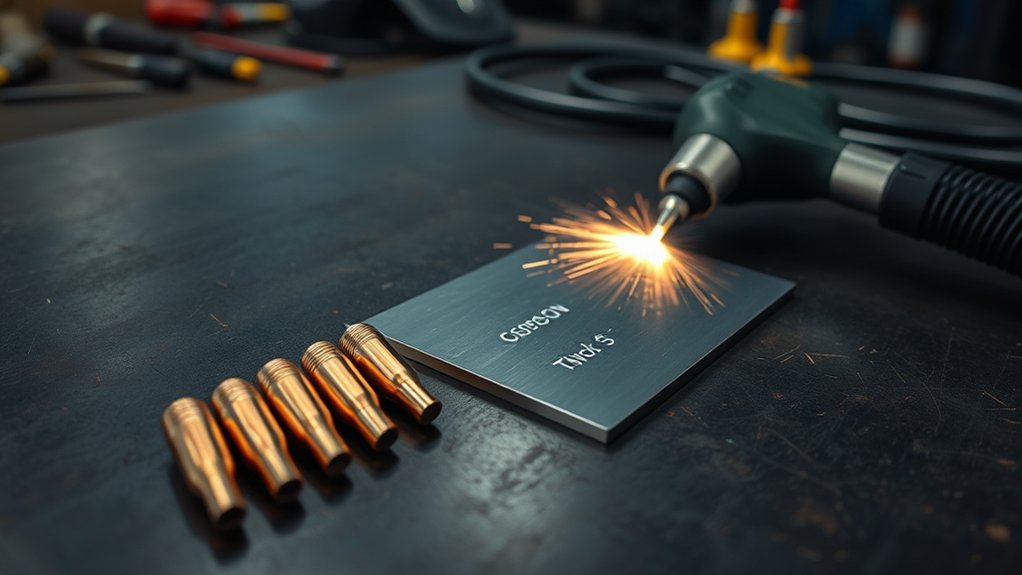
Two variables drive clean plasma cuts: amperage matched to thickness and travel speed matched to heat input.
Set amperage settings by thickness: for manual cutting, plan roughly 20 amps for the first 1/8 inch, then add 10 amps per additional 1/8 inch. For example, 1/4 inch material typically needs about 50 amps to maintain full penetration and a stable kerf.
For CNC, halve the manual requirement: 20 amps aligns with about 1/16 inch. This reduction reflects steadier motion and tighter torch control.
Coordinate travel speed with heat input. Manual work targets about 10–15 IPM; automated motion can exceed 100 IPM.
Too slow overheats the edge, widens kerf, and causes dross buildup; too fast undercuts, leaves unsevered webs, and narrows kerf irregularly.
Adjust travel speed incrementally to keep the arc trailing slightly behind the leading edge of the kerf with minimal drag lines.
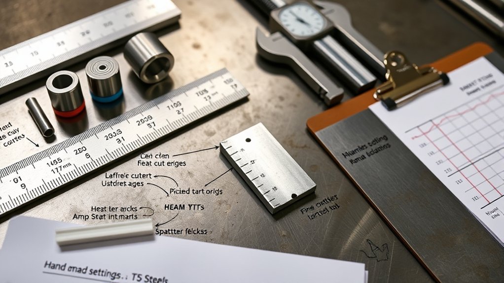
Verify by inspecting cut face uniformity, kerf width consistency, and complete separation.
Pierce Height, Standoff, and Voltage for Clean Cuts
Although amperage and speed set the thermal budget, you lock in cut quality with correct pierce height, steady standoff, and calibrated arc voltage. Set pierce height at 1.5–2× the cutting height to shield the nozzle from blowback; then drop to the programmed cutting height before motion. This practice extends consumable life and stabilizes the arc. Maintain a constant standoff distance with a height control system; fluctuations skew bevel angle and widen tolerances. Tune arc voltage to hold height: higher voltage lifts the torch, often increasing angularity; lower voltage reduces height and risks dross.
- Confirm sparks trail 15–30° behind the torch; adjust speed or height until they do.
- Validate with a test coupon and inspect bevel symmetry and dross line.
| Parameter | Target/Range | Effect on Quality |
|---|---|---|
| Pierce height | 1.5–2× cutting height | Prevents splashback, protects tip |
| Standoff distance | Constant, per chart | Controls bevel, consistency |
| Arc voltage | Per process spec | Sets height; too high = angular cuts |
Kerf Compensation and Cut Path Offsets
With pierce height, standoff, and arc voltage stabilized, you need to program kerf compensation so the cut path yields nominal dimensions. Offset the toolpath by half the kerf width to the correct side of the geometry: outside for external contours, inside for holes and pockets. This preserves plasma accuracy on finished features.
Base your offset on a plasma kerf chart matched to material and thickness. Kerf width is typically slightly larger than the tip orifice and grows as travel speed decreases. Smaller tips generally cut a narrower kerf, but verify with test coupons and measure actual slot width. Record the measured kerf and update your CAM library for repeatability.
Base offsets on kerf charts, then verify with test cuts. Measure, record, and update CAM for repeatable accuracy.
Apply adaptive rules: increase offset for slower feedrates, reduce it when cutting thin stock fast. Use consistent lead-ins/lead-outs so the compensation doesn’t bias corners.
Proper kerf management reduces rework and scrap, improves nest density, and guarantees parts meet nominal dimensions without recuts.
Brand Differences: Using Charts Across Plasma Cutters
You can use cross-brand cutting charts as a starting point, but quantify differences: Hypertherm data typically tracks closer to spec than “B-grade” machines, especially on tip size, amperage, and psi.
For a 20 A (0.6 mm) tip, confirm the manufacturer’s amperage and air pressure and then bracket-test in small increments (e.g., ±2 A, ±5 psi) to account for machine variance.
Apply lessons from RW45 chart development—validate on your unit, log results, and standardize settings once repeatability is within tolerance.
Cross-Brand Chart Compatibility
Even when materials and thickness match, cross-brand plasma cutting charts rarely translate because tip sizes, amperage windows, voltage, and air pressure baselines differ by manufacturer and model.
For true cross brand compatibility, you should anchor decisions to manufacturer guidelines for your exact torch, consumables, and power supply. Hypertherm-style charts may look universal, but component tolerances, nozzle orifice geometry, and flow rates shift the operating point, affecting kerf, speed, and cut angle.
- Verify nozzle/tip size-to-amp pairings per model; nominal amps often differ by ±5–15 A across brands.
- Match supply voltage and arc voltage targets; off-by-5–10 V can widen kerf and dross.
- Set air pressure/flow to spec; misalignment skews cooling and arc constriction.
- Use brand-specific kerf and speed tables to maintain dimensional accuracy.
Adjusting for Machine Variance
Cross-brand charts rarely map 1:1 because machines don’t share the same amperage curves, orifice geometry, arc voltage calibration, or air delivery.
Treat any borrowed chart as a baseline, then adjust for machine calibration and performance variability. Start with the manufacturer’s chart for your cutter, noting nozzle orifice size and recommended amperage; these govern current density and kerf.
Hypertherm charts trend reliable, but “b grade” units often drift in output, so expect deviations in speed, kerf width, and dross.
Validate settings with test cuts on scrap. Record arc voltage, actual current (if displayed), cut speed, stand-off, and gas pressure.
Iterate until edge angularity and dross meet spec. If kerf widens, reduce amperage or step down nozzle size. Always cross-check the user manual when switching thicknesses or materials.
Quick Reference Charts for Steel, Stainless, and Aluminum
You’ll use the Steel Tip/Amp Chart to match thickness to amperage (20 A per first 1/8 in, +10 A per additional 1/8 in) and select tip sizes from 0.6 mm to 1.3 mm with corresponding air pressures.
For stainless, follow a conservative Settings Guide—similar amps to steel but prioritize stable arc and slightly higher gas pressure; e.g., a 0.9 mm tip runs 31–40 A at 65–70 psi.
For aluminum, plan roughly 2× the steel amperage and apply Aluminum Kerf Offsets larger than the orifice, accounting for increased kerf with slower travel.
Steel Tip/Amp Chart
Precision starts with matching tip size, amperage, and air pressure to the material. For steel, tip selection and material compatibility drive cut quality, kerf control, and duty cycle.
Use the chart values below to set a baseline, then fine-tune travel speed and standoff for edge fidelity.
- 20 A tip (0.6 mm/.025): run 15–20 A at 50–55 psi. Best for thin steel; expect a narrow kerf and minimal heat input.
- 30 A tip (0.8 mm/.030): run 21–30 A at 55–60 psi. Balanced choice for moderate thickness with stable arc density.
- 50 A tip (1.0 mm/.040): run 41–50 A at 65–75 psi. Suited to thicker sections; increases kerf and penetration.
- 70 A tip (1.2 mm/.047): run 61–70 A at 75–80 psi. Maximizes throughput on heavy steel.
Remember: kerf width slightly exceeds orifice size; increasing amperage requires the corresponding larger tip.
Stainless Settings Guide
Building on steel tip/amp baselines, stainless demands tighter control of amperage, tip size, and air pressure to manage heat tint and kerf stability.
For stainless steel, apply these cutting techniques: use a 30 amp tip (0.8 mm/.030) at 21–30 A with 55–60 psi. Step up to a 40 amp tip (0.9 mm/.035) at 31–40 A with 65–70 psi. For heavier sections, run a 50 amp tip (1.0 mm/.040) at 41–50 A with 65–75 psi.
Begin with the manufacturer’s settings, then fine‑tune for dross, bevel, and arc lag. As a quick load rule: up to 1/16 in uses ~20 A; add ~10 A for each additional 1/8 in.
Maintain consistent standoff, dry air, and steady travel to minimize discoloration and taper.
Aluminum Kerf Offsets
Two variables drive aluminum kerf offsets: higher amperage demand and speed sensitivity.
You’ll run roughly double the current versus steel, which expands the aluminum kerf and magnifies error if travel slows. Use cutting techniques that hold speed constant and match tip orifice to the planned amperage.
Because aluminum kerf exceeds the tip orifice slightly, choose a tip that supports the target current without excessive arc flare. Apply kerf compensation from a chart tied to alloy and thickness; then verify with a short test cut.
1) Set amperage ≈2× steel for the same thickness; confirm duty cycle and gas flow.
2) Maintain higher travel speed; slower passes widen kerf.
3) Offset toolpath by charted kerf value (typically 1.5–2× material thickness).
4) Select tip size to balance arc focus and heat input.
Frequently Asked Questions
How Do Humidity and Air Quality Affect Tip Life and Cut Quality?
Humidity effects and air quality directly shorten tip life and degrade cut quality. You’ll see increased arc instability, double-arcing, dross, and bevel. Keep dew point below supply temperature, use ISO 8573-1 Class 2-3-1 air, and maintain filtration/drying.
What Maintenance Schedule Extends Tip and Electrode Lifespan?
Schedule daily inspections, weekly consumable audits, and monthly system calibration. You replace electrodes at 0.040–0.060 in wear, tips at orifice ovalization >10%. Standardize maintenance frequency, perform tip cleaning after every shift, verify airflow/dryness, log arc starts, and track voltage rise.
How Can I Troubleshoot Double Arcing or Tip Blowouts?
Cut to the chase: verify tip alignment, inspect electrode wear, and match power settings to material. Check gas pressure per spec, guarantee clean, dry air, and proper standoff. Replace damaged consumables. Update grounding, torch swirl ring, and lead connections.
Which Consumable Materials Best Resist Corrosion in Humid Shops?
Choose nickel‑plated copper, silver‑bearing copper, and tungsten‑insert electrodes; they offer superior corrosion resistance in humid shops. Verify ASTM B152/B700 compliance, <10 µS/cm rinse-water use, sealed storage ≤40% RH, desiccant packs, and ISO 14644 clean handling to prolong consumable materials life.
How Do CNC vs. Handheld Torches Influence Tip Selection?
You treat CNC like a laser-guided metronome; you pick smaller, precision tips for repeatability. Handheld’s a wild stallion; you choose larger, forgiving orifices. Evaluate torch advantages, tip compatibility, duty cycle, standoff control, amperage windows, ISO tolerances, consumable stack geometry.
Conclusion
You’ve seen how tip orifice, amperage, and air pressure lock together to control kerf, speed, and quality. Use the charts to pick tip size by current and metal thickness, then set pierce height, standoff, and voltage to spec. Calibrate kerf compensation in CAM to maintain dimensional tolerance. One data point: a 0.9 mm tip at 40 A typically yields a 1.2–1.4 mm kerf in steel. Validate with test cuts, document settings, and standardize for repeatability.