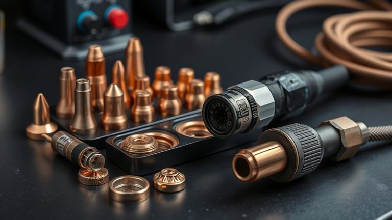
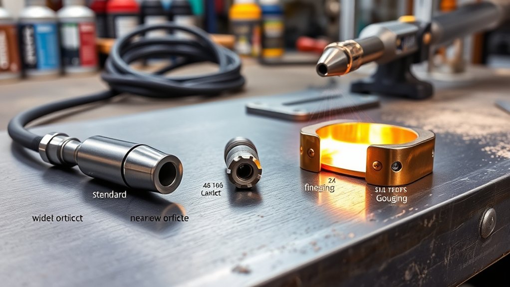
Choosing the right plasma tip, Standard, FineCut, or Gouging, directly affects kerf (the cut width), edge quality, and productivity. Match the tip and amperage to material thickness, then tune standoff (tip-to-work distance), travel speed, and gas flow so the arc stays stable. Standard tips handle everyday cutting on thicker stock, FineCut sharpens detail on thin sheet, and Gouging is for controlled metal removal. Set up the torch, ground, and consumables correctly, or cut quality and consumable life will drop fast.
Quick Answer
- Standard tips are the go-to for general cutting and faster throughput on thicker material, with a wider kerf.
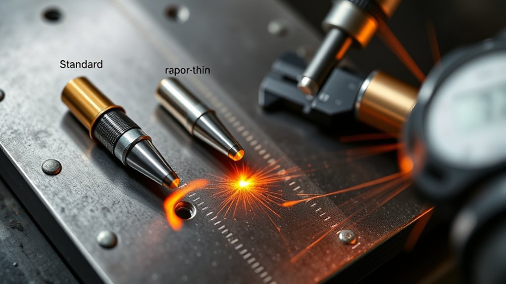
- FineCut tips focus the arc for a narrower kerf and cleaner detail on thin sheet, usually at lower amps.
- Gouging tips are for shaping or removing metal (weld prep, weld removal, cleanup), not for through-cuts.
- Match tip size and amperage to thickness, then fine-tune standoff, travel speed, and gas pressure/flow to keep the arc steady.
- A clean ground connection and clean, dry air are two of the biggest drivers of consistent cut quality and longer consumable life.
Understanding Standard, FineCut, and Gouging Tips
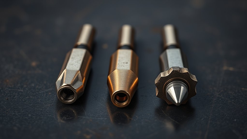
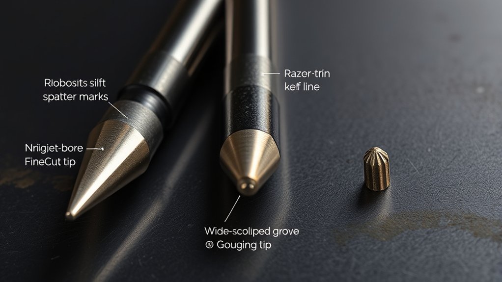
Precision starts with matching the tip to the job: standard tips for fast, general cutting with a wider kerf on thicker stock; FineCut tips with smaller orifices and lower amps for narrower kerfs on thin sheet; and gouging tips engineered to remove metal cleanly with consistent gouge profiles.
Tip compatibility is a real control variable, not an afterthought. Standard tips favor higher amperage and faster travel speeds, trading a wider kerf for throughput. FineCut versions tighten the arc column with a smaller orifice and a lower amp window, which helps reduce heat input and keep edges crisp on light gauge. Gouging tips reshape the plume so it pushes metal out efficiently, which can cut down on post-process grinding.
Dial in performance factors, amperage, gas pressure, stand-off, and travel speed, to the tip’s spec window. Run too hot and you’ll erode the orifice. Run too low and the arc can get unstable.
Verify gas pressure per your machine’s rating to maintain arc density. Select the tip type, then tune parameters to lock in quality, speed, and precision. If you want a reliable example of how manufacturers lay this out, see cut charts and consumable selection guidance.
When to Choose Standard Tips
When throughput and versatility matter, choose a standard tip for general cutting across a broad thickness window, commonly mild steel up to about 1 inch, matched to the machine’s amperage.
Standard tips make sense when you need fast, dependable cuts across mixed jobs and materials without swapping consumables constantly. They’re a solid choice when kerf needs to balance speed and edge quality, with minimal dross and less cleanup.
Select them for plate work and structural parts where productivity matters more than ultra-fine detail. Set amperage to thickness, hold a consistent standoff, and keep a steady travel speed to protect kerf geometry and penetration.
Pick standard tips for plate and structural work, set amperage, standoff, and steady speed for a clean kerf.
Standard tips excel on thicker stock, delivering higher cutting speeds than fine-detail options and staying compatible across most shop and field plasma systems.
Prioritize consumable health: inspect the orifice for ovaling, watch arc stability, and replace at the first signs of increased dross or reduced cut depth to maintain peak performance.
When to Choose FineCut Tips
Choose FineCut tips when thin sheet precision and tight kerf requirements call for a more focused arc and lower heat input.
You’ll run lower amperage to stabilize the arc, reduce dross, and maintain clean edges on aluminum or mild steel. FineCut is generally aimed at thinner material (often 3/16 inch and under at lower amperage ranges), and exact cut charts vary by torch and machine.
Inspect the smaller orifice regularly. Replace at the first sign of pitting or irregularity to preserve cut quality.
Thin Sheet Precision
FineCut tips earn their place when you’re cutting thin sheet and need tight kerf control, clean edges, and minimal distortion. On thin metal, the smaller orifice and lower amp window help stabilize the arc, shrink the heat-affected zone, and keep delicate stock flatter.
- Select the FineCut orifice matched to material thickness; stay within the manufacturer’s low-amp range.
- Dial amperage down until dross rises, then bump slightly up to land the cleanest edge.
- Set gas pressure to spec; overpressure widens the arc and erodes kerf fidelity.
- Use a tight standoff and consistent cut height to maintain arc focus and minimal warp.
- Favor FineCut for intricate geometry, tight tolerances, automotive skins, and artistic detail.
Tight Kerf Requirements
Precision on thin sheet sets the stage for tight kerf requirements, where you prioritize a narrow cut, low heat input, and edge fidelity.
When precision cutting is non-negotiable, choose FineCut tips. Their smaller orifice focuses the arc, producing a narrower kerf that threads through tight geometries and holds tolerance in intricate designs.
Pair tip selection with thickness and amperage. On thin material, many air-plasma FineCut setups run around 40 amps and below, but your cut chart is the final word for your torch and machine.
You’ll see reduced warping, cleaner edges around radii and pierces, and better part fit-up. Validate with test coupons, then lock in cut height, lead-ins, and feed rate to hold profile accuracy without overburn.
FineCut excels where clearance is scarce and detail matters.
Low-Amp, Clean Edges
When low amperage and clean edges are the priority, you’ll reach for FineCut tips to control kerf and heat input on thin stock. You’ll leverage low amp benefits, typically 20–60 amps, to tighten the arc and protect the heat-affected zone.
The smaller orifice focuses energy, enabling clean edge techniques on thin material without excessive dross or warping. Choose FineCut when geometry is intricate, tolerances are tight, and finish quality matters for both aesthetic panels and functional parts.
- Set amperage to the low end of the chart; tune pierce and cut speeds to prevent overburn.
- Maintain correct standoff with a height control to stabilize arc density.
- Use dry, clean air; moisture increases dross.
- Inspect tips frequently; replace at the first signs of orifice erosion.
- Program lead-ins/outs to minimize heat soak and edge rounding.
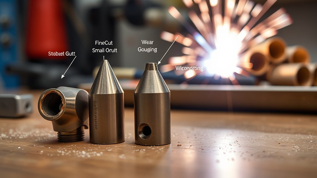
When to Choose Gouging Tips
Although standard cutting tips can muscle through many tasks, you’ll choose gouging tips when the job calls for controlled metal removal rather than through-cuts, think weld prep, weld removal, and surface cleaning.
For these gouging applications, switch your system to gouging mode, if available, so gas dynamics and arc characteristics bias toward material removal, not kerf formation.
You’ll favor gouging tips when you need predictable groove profiles without excessive cleanup. They support precise gouging techniques: vary torch angle to tune gouge width, adjust standoff to stabilize arc attachment, and modulate travel speed to manage depth uniformity.
Higher amperage drives wider, deeper channels; lower amperage yields narrow, shallow passes, letting you sneak up on the final profile.
Use gouging when removing defective welds, beveling for re-weld, or stripping coatings and contaminants without piercing.
The resulting consistency can reduce secondary grinding, shorten cycle time, and preserve base metal integrity by minimizing over-removal and heat input.
Matching Tip Size and Amperage to Material Thickness
Gouging has its place, but cutting performance hinges on pairing tip size and amperage to the stock on the table. Nail tip selection by aligning orifice size and current with material compatibility and thickness.
Standard tips push higher amperage for thicker sections and a wider kerf. FineCut tips favor thin sheet with a tighter kerf and lower current. Undersizing the tip or overpowering thin stock hurts edge quality and burns through consumables.
- Use a 20A tip for up to 1/8 in; expect a fine kerf and clean edges on light gauge.
- Step to 30A for ≤3/16 in; maintains arc stability without overburn.
- Choose 40A for ≤3/8 in; balances speed, dross control, and kerf width.
- Run 50A on 1/2 in and 60A for ≤5/8 in; standard tips deliver energy density for full penetration.
- Reserve gouging tips for material removal; vary amperage and standoff to tune depth and profile.
Match amperage to tip rating; mismatches cause blowout, bevel, and premature wear.
Setting Up Your Torch and Ground for Best Results
Before you strike an arc, clamp to clean, bare metal for a low-resistance return path and stable arc starts.
Fit the torch with the correct consumables, match nozzle size to cut or gouge mode, keep the torch near 90° for cutting, and use a 30–40° lead angle for gouging. Hold a consistent standoff (often around 1/16–1/8 inch, depending on your shield and chart).
Verify gas type and pressure, confirm the machine is in the proper mode, and inspect nozzles and electrodes for wear.
Clean, Secure Ground
Even with the right consumables and amperage, a weak ground will sabotage plasma performance. You need a clean, secure path for current return to maintain arc stability and cut quality. Prioritize the ground clamp and electrical connectivity before striking an arc.
- Attach the ground clamp to clean, bare metal on the workpiece; avoid painted, rusty, or oily surfaces that throttle current.
- Place the clamp close to the cut zone to minimize resistance and voltage drop, tightening jaws fully for maximum contact area.
- Mechanically clean the contact patch, grind off rust, paint, or mill scale, to lower interface impedance and prevent misfires.
- Inspect the ground cable routinely; replace abraded insulation, repair broken strands, and torque lugs to spec.
- Use a dedicated ground point (e.g., a welding table) for a consistent reference, reducing arc wander and intermittent starts.
Correct Torch Setup
While the machine’s amperage matters, your cut quality hinges on correct torch setup and a solid return path. Start with safety precautions: power down, lockout, and let components cool.
Verify the ground clamp bites clean metal near the cut zone to minimize resistance and stabilize arc initiation.
Select the correct consumables for the job, standard, FineCut, or gouging, and match them to material and thickness. Set the system’s operating mode accordingly; if you’re gouging, enable gouging mode to align current ramp and arc characteristics.
Perform torch adjustment: confirm electrode and nozzle seating, inspect the shield, and replace worn parts. Set standoff to roughly 1/16–1/8 inch to control arc length and kerf.
Finally, tug-test leads, check strain reliefs, and schedule inspections to prevent intermittent arcs and inconsistent quality.
Verify Gas Supply
Because gas quality and pressure drive arc stability, verify your supply before you strike. Start by confirming the correct gas type, clean, dry air or the specified mix, so you’re not feeding contamination into the torch.
Then set gas pressure to the machine spec and confirm it under flow. Many hand-held air plasma systems run best around 70–80 PSI, but the exact value depends on the torch and model. For a solid overview of what low or high pressure does to cut quality, see how air pressure affects plasma cut quality. Lock in your ground: clamp on clean metal, as close to the work as possible.
- Set regulator to the required gas pressure; confirm at the torch under flow.
- Purge lines to clear moisture/oil; use a dryer and filter.
- Inspect hoses/fittings; leak-test with approved solution.
- Verify inlet and torch connections are fully seated.
- Place the ground clamp close; clean contact boosts arc stability.
Technique Differences: Cutting vs. Gouging
Think of plasma cutting and gouging as two modes of the same toolset with different goals and setups.
For cutting, you chase cutting precision: a focused arc, square edges, and minimal dross. You run standard or FineCut consumables, FineCut on thin stock for a tighter kerf and cleaner detail. The torch stays near perpendicular, amperage matches material, and you maintain a consistent arc for clean separation.
Gouging flips the objective. You’re sculpting metal, not severing it. Effective gouging techniques start with a handheld torch angled about 30–40 degrees to push molten metal out of the groove.
Gouging is about controlled removal, not separation. Angle the torch about 30–40 degrees to sweep molten metal out.
Select a gouging tip engineered for broad, deep channels in thicker materials. Modulate amperage to set depth potential, then fine-tune with torch height and steady travel to control profile. Expect a textured groove that may need post-pass grinding.
In short: cutting prioritizes edge quality and accuracy; gouging prioritizes controlled material removal and groove geometry.
Managing Kerf Width, Standoff, and Travel Speed
Cutting and gouging share the same torch, but you control outcomes by managing kerf width, standoff, and travel speed. Dialing these three variables gives you predictable edges and repeatable gouge profiles.
For kerf management, match nozzle size to the job: smaller or FineCut nozzles tighten kerf on thin stock; larger nozzles open it up for heavier sections.
Hold a consistent standoff, target 1/16–1/8 inch, to stabilize arc geometry, minimize dross, and keep cut face straighter.
Then execute travel optimization: set speed to balance width, depth, and slag.
- Choose nozzle size to set baseline kerf; smaller equals narrower, cleaner detail.
- Maintain 1/16–1/8 inch standoff to lock arc focus and reduce dross.
- Adjust travel speed: slower widens/deepens; faster narrows/shallows, tune per material.
- Modulate amperage: higher widens kerf; lower tightens it; coordinate with speed.
- For gouging, pair torch height and speed to hit target depth and keep profiles uniform.
Consumable Care and Replacement Timing
Even with a well-tuned torch, consumables dictate cut quality and reliability, so manage them with the same discipline you give standoff and speed. Build a routine around inspection and replacement timing. Check nozzles for ovality, dings, and spatter bridging; retire any tip with an irregular or enlarged orifice. Track electrode pit depth: swap standard copper at 0.040 in; replace silver/hafnium interface at 0.080 in. Moisture, poor pierce height, and dragging the shield can accelerate wear, so tighten technique to extend life. Always match part numbers from the operator’s manual to avoid compatibility-driven bevel, dross, and hard starts. Keep spares staged to prevent downtime.
| Consumable | Inspection cue | Replacement action |
|---|---|---|
| Nozzle | Irregular hole, spatter | Replace immediately |
| Electrode (Cu) | 0.040 in pit | Replace |
| Electrode (Ag/Hf) | 0.080 in pit | Replace |
| O-ring/Shield | Cracks, flattening | Replace/lube per spec |
Log hours, material, and amperage so you can predict changeouts and maintain cut consistency.
Frequently Asked Questions
Are Finecut Tips Compatible With Drag Shields on Handheld Torches?
Yes, but only with model-specific consumables and matching shield caps. Verify FineCut compatibility in your torch’s manual. For drag shield usage, maintain correct standoff, amperage, and travel speed. Don’t freehand-touch; use a guide to prevent orifice damage.
Do Different Tip Types Require Distinct Air Filtration or Drying?
Yes. Air quality matters more as the orifice gets smaller. Standard tips can tolerate basic coalescing filtration, while FineCut often benefits from better drying and filtration. Gouging is generally more forgiving, but moisture can still destabilize the arc and shorten consumable life.
Can I Mix Tip Brands Across Different Plasma Torch Models?
You generally shouldn’t mix tip brands across different plasma torch models. Tip brand compatibility hinges on electrode geometry, gas flow orifices, standoff, and swirl ring interfaces. Verify torch model variations, consumable stack tolerances, and OEM current ratings before substitution.
How Do Tip Types Affect CNC Cut Quality and Nesting Efficiency?
Orifice size, swirl ring match, and amperage rating drive kerf width, dross, and edge taper. When you optimize those variables, you boost cut quality, shrink kerf width, tighten lead-in distances, and improve nesting efficiency.
What Storage Conditions Prevent Tip Oxidation and Contamination?
Store tips in sealed, desiccated containers at 20–25°C, low humidity (<30% RH), away from chlorides and ozone. Use clean nitrile gloves, individual compartments, dust caps, and silica gel. Implement FIFO, periodic inspections, ensuring tip storage and contamination prevention.
Conclusion
You’ve got the right tip for the right job, now make the cut. Use Standard for general stock, FineCut for thin precision, and Gouging when you need controlled metal removal. Match tip size and amperage to thickness, confirm standoff and travel speed, and lock in a solid ground. Distinguish cutting vs. gouging technique, manage kerf, and monitor consumables. When arc quality drifts, swap parts. Execute the process repeatably, safely, and efficiently.