
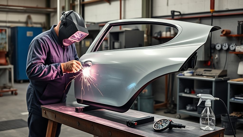
You can improve auto body panel weld quality by doing most of the important work before you strike an arc. Identify the panel material, follow the vehicle maker’s repair procedure, clean and fit the metal precisely, test the welder on matching scrap, and use short welds with cooling time between them. The methods below apply mainly to nonstructural mild-steel panels. Structural steel, aluminum, and hybrid or electric vehicles may require different equipment and procedures.
Quick Answer
To improve auto body panel weld quality, verify the OEM repair method, clean both sides to bare metal, make the patch fit evenly, test your settings on matching scrap, and use short, spaced tack welds. Let the panel cool naturally, inspect for full fusion and pinholes, then restore corrosion protection.
Key Takeaways
- Check the vehicle-specific body repair procedure before choosing a weld type or sectioning location.
- Clean metal, accurate fit-up, a nearby work clamp, and steady panel support matter as much as the machine settings.
- Use short, spaced tacks and stitch welds instead of one long bead on thin exterior panels.
- Match the filler wire, shielding gas, polarity, and joint design to the material and approved repair method.
- Disconnect vehicle electrical systems according to the OEM procedure and leave hybrid or EV high-voltage work to qualified personnel.
- Finish the repair with controlled grinding, inspection, epoxy primer, seam sealer, cavity wax, and the specified paint system.
At a Glance
| Time Required | About 30 minutes for setup and testing; one to several hours for fitting, welding, grinding, inspection, and corrosion protection |
| Difficulty | Moderate to advanced because thin sheet metal burns through, shrinks, and warps easily |
| Tools Needed | Approved welder and wire, welding helmet, gloves, protective clothing, ventilation or fume control, clamps, backing bar, grinder, wire brush, solvent, matching scrap, and fire extinguisher |
| Cost | Low if you already own suitable welding gear; higher when gas, wire, PPE, clamps, primer, seam sealer, cavity wax, and finishing supplies are needed |
Warning: Welding can cause fire, eye injury, burns, electric shock, harmful fume exposure, vehicle damage, and ignition inside hidden cavities. Wear the correct PPE, ventilate the work area, inspect both sides of the panel, keep an extinguisher ready, and follow the vehicle maker’s battery and high-voltage shutdown procedure. Do not weld when fuel vapor, leaking refrigerant, or another explosive atmosphere may be present.
Set Up Safely Before You Weld
Before you focus on weld appearance, make the work area fire safe. Remove carpet, insulation, seam sealer, undercoating, sound deadener, paper, oily rags, plastic trim, and other materials that sparks or conducted heat could ignite. Check the back side of the panel and every nearby cavity because sparks can travel through holes, seams, and structural openings.
OSHA’s welding, cutting, and brazing requirements call for movable fire hazards to be removed and immovable hazards to be shielded. A fire watch is required under listed higher-risk conditions, including when appreciable combustible material is within 35 feet or sparks can reach hidden combustibles. When a fire watch is required, it must continue for at least 30 minutes after welding stops.
Keep a suitable fire extinguisher ready for immediate use. After the final weld and grinding pass, inspect the opposite side of the repair, nearby trim, floor coverings, cavities, and seam sealer for heat, smoke, odor, or smoldering material.
Protect yourself with a welding helmet or hand shield during arc welding and use a filter shade suited to the welding current. OSHA’s eye and face protection rule lists shade guidance for welding operations. Wear safety glasses under the helmet, leather welding gloves, non-synthetic protective clothing, closed footwear, and hearing protection while grinding.
Welding fumes can contain metals and substances from the base material, filler wire, coatings, paint, and old body-repair products. The CDC/NIOSH welding fume guidance explains the health risks associated with manganese and other welding exposures. Use local exhaust ventilation or fume extraction, keep your head out of the plume, and use a correctly selected and fitted respirator when the hazard assessment requires one.
Verify the Panel Material and Vehicle Systems
Do not assume that every metal panel can be repaired with the same wire, heat, or joint. Before cutting or welding, find the vehicle-specific body repair information and identify the panel material, tensile strength, approved sectioning location, joint design, weld type, weld spacing, filler wire, shielding gas, and corrosion-protection steps.
Modern bodies may contain mild steel, high-strength steel, ultra-high-strength steel, aluminum, magnesium, layered reinforcements, adhesives, rivets, and factory spot welds in the same area. Honda’s current welding and sectioning guidance, for example, permits or prohibits different welding methods according to steel strength and limits some plug welds to model-specific locations. Other vehicle makers use their own requirements.
Disconnect the 12-volt battery only in the order and for the waiting period specified by the vehicle maker. Some modules, airbag systems, electronic parking brakes, windows, steering systems, and security functions require special preparation or initialization. Do not use a generic battery-disconnection routine when manufacturer instructions are available.
Hybrid and electric vehicles require additional precautions. High voltage may remain present even after the ignition is switched off or the 12-volt battery is disconnected. A qualified person must follow the exact OEM procedure to de-energize, verify, lock out, and later restore the high-voltage system. A Subaru hybrid body-welding bulletin, for example, requires removal of the model’s high-voltage service disconnect before welding.
Inspect behind the repair for fuel tanks, fuel and vapor lines, brake lines, coolant hoses, refrigerant lines, airbag components, wiring harnesses, sensors, sound deadener, and closed cavities. Move or protect them according to the repair manual. Do not vent a motor-vehicle air-conditioning system. When refrigerant removal is necessary, use approved recovery equipment and follow the applicable EPA motor-vehicle air-conditioning servicing requirements.
Attach the welding work clamp to clean bare metal as close to the repair as practical. A short, direct current path helps stabilize the arc and reduces the chance of welding current passing through bearings, hinges, wiring, modules, or sensitive vehicle components. Never attach the work clamp to a painted, rusty, loose, or insulated surface.
Note: Do not weld a structural rail, pillar, rocker reinforcement, suspension mounting area, airbag zone, or HSS/UHSS component unless the vehicle-specific procedure permits the exact repair. Some parts require squeeze-type resistance spot welding, MIG brazing, adhesives, mechanical fasteners, complete replacement, or a specific combination of methods.
Prevent Burn-Through on Auto Body Panels
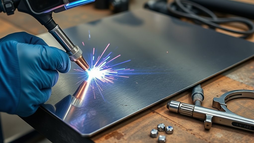
Burn-through can ruin an auto body repair quickly, especially when an old panel has thin, rust-pitted, stretched, or previously ground edges. Control heat from the start with the lowest stable machine setting that produces clean fusion, a short arc, brief weld duration, and accurate joint fit-up. Do not hold the arc on one spot while waiting for the puddle to grow.
Clean the weld zone thoroughly before you strike an arc. Bare, contaminant-free metal welds more predictably than metal covered with paint, rust, adhesive, seam sealer, undercoating, oil, moisture, or old filler. Welding over contamination raises the risk of porosity, spatter, unstable fusion, fire, and harmful fumes.
Give each tack time to cool before adding the next one. Move to a distant part of the seam instead of welding adjacent spots while the metal is still hot. This distributes heat and reduces concentrated shrinkage.
Natural cooling is the safest general approach. Do not quench a panel weld with water. Clean, dry compressed air may be used only when the OEM procedure permits it and only after the weld has solidified. Avoid blasting grinding dust, solvent, moisture, or loose abrasive into the joint.
Pro Tip: Make at least three or four practice tacks on scrap that matches the panel material and thickness. After the sample cools, inspect both sides and bend, peel, or hammer-test it. If the weld pops off, stays only on one edge, turns porous, or burns through, correct the setup before touching the vehicle.
Choose the Right Welding Process and Settings
Choosing the right process is one of the biggest factors in auto body panel weld quality, but the OEM repair procedure comes first. Gas-shielded GMAW, commonly called MIG welding in repair shops, is often practical for approved mild-steel patch panels because it is fast and relatively easy to control. TIG gives precise puddle control but can add excessive heat when travel is slow. Plug welds and squeeze-type resistance spot welds are commonly used to reproduce factory flange attachments when the repair procedure allows them.
| Process | Typical Approved Use | Watch Out For |
|---|---|---|
| Gas-shielded GMAW, often called MIG or MAG | Approved mild-steel butt joints, patch panels, lap joints, and plug welds | Excess heat, incorrect wire strength, poor gas coverage, long stickout, and mismatched voltage or wire speed |
| TIG | Approved visible seams and thin edges where precise control is needed | Slow travel, a wide heat-affected zone, poor fit-up, and contamination from old coatings |
| GMA plug welds | Replacing factory spot-weld attachments on flanges when the OEM procedure permits them | Wrong hole size, a gap between layers, weak fusion into the lower panel, incorrect spacing, and trapped corrosion |
| Squeeze-type resistance spot welding | Factory-style flange attachments when access, equipment, material, and OEM instructions allow it | Worn tips, incorrect clamp force, wrong manual program, poor mating contact, and unapproved automatic settings |
| Flux-core wire | Limited non-cosmetic work only when the equipment and repair procedure permit it | Higher spatter, slag, smoke, and heat input that make thin exterior panels harder to finish |
| Aluminum GMAW or TIG | Only on approved aluminum repairs with dedicated equipment, clean tools, and the correct alloy-specific procedure | Cross-contamination, wrong filler alloy, oxide, excessive heat, and mixing steel and aluminum work areas |
Set the machine for the actual panel material and thickness. Start with the chart inside the welder door or the owner’s manual, then fine-tune on a joint made from matching scrap. Miller’s MIG parameter guide explains how voltage, wire-feed speed, material thickness, and travel speed affect bead shape, penetration, and burn-through.
If the wire repeatedly stubs into the panel, the voltage may be too low for the wire-feed speed, the contact tip may be too far from the work, or the feed system may be dragging. If the arc becomes harsh and the edge disappears, shorten the weld duration and check voltage, wire-feed speed, travel speed, stickout, and fit-up rather than changing only one setting at random.
Products Worth Considering
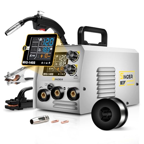
THREE-PROCESS WELDING STATION BUILT FOR FIRST-TIME USERS - Flux Core MIG, Lift TIG and Stick in one machine, so you can find the process that fits your projects without buying three separate welders. Runs on a standard 110V household outlet or 220V for heavier work - no electrician, no special wiring. Welds carbon steel, low-alloy steel, stainless steel, titanium, copper and cast iron
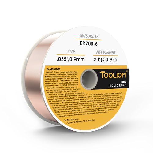
High-quality:Tooliom's .035" ER70S-6 MIG Welding Wire (2lb spool) meets all industry standards for consistent strength and performance. Enjoy smooth feeding, stable arcs, optimal penetration, and high deposition rates—everything you need for exceptional welds

Package Includes: 10ft mig gun + 1pcs nozzle +1pcs diffuser + 6 tips (.023", .030", .035" - two of each size). This mig gun uses the same consumables as the Tweco Mini/#1. 21-50 nozzle, 35-50 diffuser, 11-series contact tip.
Choose the Correct Wire, Gas, Polarity, and Ground
Small-diameter solid wire, such as 0.023-inch wire, is a common starting choice for thin mild-steel panels when the welder supports it. That does not make it correct for every repair. High-strength steel may require filler wire with a higher tensile strength, and MIG brazing uses a different filler and shielding gas. Follow the OEM specification rather than choosing wire only by diameter.
Use the polarity required by the wire and machine. Gas-shielded solid wire normally uses direct-current electrode positive, while many self-shielded flux-core wires use a different polarity. Confirm the label and welder manual. Use the specified shielding gas, keep the cylinder secured upright, check hoses and fittings for leaks, clean the nozzle, and protect the weld from drafts without blocking ventilation.
Prep Sheet Metal for Cleaner Welds
Clean sheet metal is the foundation of a strong, consistent weld. Remove paint, rust, oil, adhesive, seam sealer, scale, oxidation, and grinding dust from the weld zone. Clean both sides of the joint when access allows because contamination trapped behind the panel can boil into the weld and create porosity.
Remove only the coating necessary for the approved process. Do not strip a large area without reason because the factory coating helps protect the surrounding metal. On coated or galvanized steel, control fumes with suitable ventilation and respiratory protection based on the hazard assessment.
Fit-up is just as important as cleanliness. The correct fit depends on the joint. Butt seams may need a small, even root gap specified by the repair procedure. Lap and plug-weld flanges usually need tight mating contact without a gap between layers. Recheck panel height, contour, door or lamp openings, and body lines after tightening each clamp.
| Step | Action | Why It Matters |
|---|---|---|
| Identify | Confirm material, steel strength, layers, and the approved attachment method | Prevents an unsafe process or sectioning location from being used |
| Clean | Remove paint, rust, grease, seam sealer, scale, and oxidation from the required weld zone | Reduces porosity, weak fusion, unstable arc behavior, fumes, and fire risk |
| Trim | Cut, deburr, and lightly dress the patch edges without thinning them | Creates a consistent joint that needs less filler metal and grinding |
| Fit Butt Joint | Use the root gap and alignment specified by the vehicle maker; keep it even across the seam | Balances penetration with burn-through and distortion control |
| Fit Lap or Plug Joint | Clamp the mating flanges tightly and prepare the specified hole size and spacing | Helps the weld fuse into the lower panel and limits hidden corrosion pockets |
| Secure | Lock the panels with clamps, clips, screws, or jigs allowed by the procedure | Maintains alignment while heat and weld shrinkage try to move the panel |
If the patch sits proud, low, twisted, or heavily stressed before welding, the weld will not correct it. Trim and shape the patch until it rests in position with light, even clamping force. A clean seam that fits correctly needs less filler metal, less grinding, and less total heat.
Use Weld-Through Primer Only When the OEM Calls for It
Weld-through primer is not a universal first step for every flange or weld. Its use depends on the vehicle maker, material, joining process, and primer product. Applying it where it is not approved can contaminate the weld or reduce joint quality.
Honda’s September 2025 guidance provides a clear example: it calls for zinc-rich weld-through primer on bare mating surfaces used for squeeze-type resistance spot welding, but states that weld-through primer should not be used for MAG plug welding, MAG butt welding, or MIG brazing. For those processes, the instructions call for removing only enough factory e-coat to create the required bare weld area and applying epoxy primer over the completed joint.
Other manufacturers may specify different products and sequences. Follow the repair manual and the coating manufacturer’s instructions. After welding and inspection, restore every exposed surface that can be reached, including the back side of the seam, flange edges, cavities, and ground locations.
Control Heat With Tack and Stitch Welds
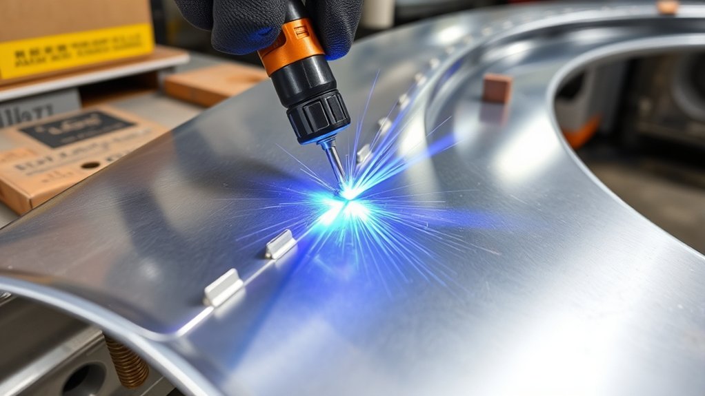
Use tack welds to lock the panels in place and divide the seam into small sections. Do not lay one long continuous bead on thin exterior sheet metal unless the material and repair procedure specifically allow it. Place the first tacks far enough apart to hold the panel shape, then add new tacks between cooled welds.
Once the joint is stable, fill the spaces with brief stitch welds or overlapping tacks as the approved repair requires. Move to a distant, cool section after each weld. Avoid repeatedly adding metal to the same hot area because that concentrates shrinkage and pulls the panel out of shape.
Use low, stable heat input rather than simply turning every control to its lowest position. The arc must still fuse into both joint edges or through the plug-weld hole into the lower panel. Keep a consistent contact-tip-to-work distance and maintain a clear view of the puddle.
Between passes, wait for the panel to cool naturally. If you are learning how to MIG weld thin metal without burning through, listen for a steady short-circuit arc and watch for the puddle to join both edges without growing wide enough to collapse them.
On an approved nonstructural outer-panel butt seam, an experienced technician may use careful hammer-and-dolly work between cooled tacks to manage minor weld shrinkage. Do not planish structural steel, inaccessible reinforcements, or any panel where the OEM procedure prohibits straightening or heat correction.
The goal is not the largest bead. It is the smallest controlled weld that produces complete, clean fusion without overheating the surrounding panel.
Use Clamps and Backing Bars for Support
Use clamps to lock panel alignment before welding so the patch remains flush and the joint keeps its intended gap. C-clamps, butt-weld clamps, toggle clamps, panel-holding clips, temporary screws, and purpose-made jigs can help maintain even pressure. Use only methods permitted by the repair procedure and remove temporary fasteners in the specified way.
A backing bar behind thin sheet metal can support the molten puddle and draw heat away from a vulnerable edge. Copper is commonly used because ordinary steel weld metal does not readily fuse to it under normal panel-welding conditions. The bar must be clean, smooth, and held tightly against the rear of the seam.
Purpose-made aluminum backing may also help in some mild-steel work, but copper is generally more forgiving. Keep the arc off an aluminum backing surface so it cannot melt and contaminate the steel joint. Do not use either material when the OEM repair method prohibits a backing bar or requires access to the reverse side for inspection.
Products Worth Considering

Value Pack: The package includes 24 packs of butt welding clamps, enough quantity to meet your daily needs and replacements. Each butt welding clamps is individually wrapped in a small bag, convenient to carry and use.

16-Pack Welding Clamps Set: Includes 16 butt welding clamps designed for precise edge-to-edge welding, ideal for body repair, floor patching, door skins, and sheet metal alignment.

Adaptability: Our butt welding clamps are suitable for both straight panels or curved panels. Maintains 0.40" gap between panels for edge-to-edge welding.They will work well in these 2 kinds of p
Clamp Panel Alignment
When aligning auto body panels for welding, secure them so they stay fixed and true throughout the process. Recheck the body line, crown, door gap, lamp opening, adjacent-panel height, and seam width before striking an arc. Verify the contour again after tightening each clamp because thin panels move easily.
Do not force a poorly shaped patch into place with welds. If heavy clamping pressure is required, trim or reshape the patch first. Welding a stressed patch can pull the surrounding panel out of shape as the weld cools and shrinks.
Backing Bar Heat Control
A tightly fitted backing bar absorbs some heat, supports the puddle, and lowers the chance of an edge falling away. Clamp it securely so it cannot shift while the arc is active. A loose backing bar leaves an air gap and provides much less support.
- Secure clamps lock alignment before heat moves the panel.
- Tight backing-bar contact improves puddle support and heat transfer.
- A clean backing surface reduces contamination and makes removal easier.
- The backing bar does not replace correct fit-up or suitable machine settings.
Backing bars help most when the joint is accessible from behind. If the back side cannot be reached, improve the fit, shorten each weld, allow more cooling time, and prove the settings on scrap before welding the vehicle.
Match Wire Speed and Travel Speed
Matching wire-feed speed with voltage and travel speed is essential for consistent bead shape and complete fusion. On a constant-voltage MIG machine, increasing wire-feed speed generally increases welding current. The voltage affects arc length and bead profile, while travel speed and weld duration strongly affect how much heat enters the panel.
If you move too slowly or hold the trigger too long, the bead grows wider and the risk of burn-through and distortion rises. If you move too fast, the weld may become narrow and sit on top of the joint without joining both edges. If the wire-feed speed is too high for the voltage, the wire can push into the work. If the voltage is too high for the joint, the arc may become harsh and wash away the edge.
If weld quality changes during the repair, stop and check the entire system. Look for MIG welding problems and solutions such as a dirty contact tip, worn liner, feed-roll slip, incorrect drive-roll tension, poor work-clamp contact, wrong polarity, an empty gas cylinder, a blocked nozzle, hose leaks, or drafts across the joint.
Practice on scrap that matches the panel thickness, coating condition, and joint style. When possible, cut a coupon from the removed original panel. That gives you a realistic test for wire-feed speed, voltage, travel speed, heat, cleanliness, and joint fit.
Test Weld Before Touching the Panel
A test weld can save the repair. Use scrap with the same material, thickness, coating preparation, number of layers, and joint design as the vehicle panel. Clamp it the same way and make the same tack, stitch, butt, plug, or spot weld planned for the vehicle.
After the test cools, inspect the face and reverse side. Look for complete tie-in, no holes, no cracks, no heavy undercut, and no clusters of pinholes. A small amount of heat tint on the back of a thin butt-joint coupon may help show that heat reached the root, but appearance alone does not prove adequate strength.
For a plug-weld test, peel or chisel the upper coupon away after cooling. A sound test should pull a fused nugget or tear material from the lower coupon rather than allowing the filled plug to pop cleanly out of the hole. Compare the nugget size and test method with the OEM requirement.
For a butt-weld coupon, bend or hammer-test the sample after it cools. The seam should not separate with light handling, and the weld should not be a tall ridge sitting only on top of one edge. Repeat the test whenever the material, wire, gas, machine setting, joint, or access angle changes.
Note: A smooth-looking bead is not proof of a strong repair. A small weld with complete fusion is better than a tall, polished bead that never joined the lower panel or both sides of a butt seam.
Troubleshoot Common Panel Welding Problems
If weld quality changes during the repair, stop and correct the cause before adding more heat. Most panel-welding defects become harder to repair after they are covered with additional weld metal or ground below the panel surface.
| Problem | Likely Cause | Fix |
|---|---|---|
| Burn-through | Excess heat, long trigger time, slow travel, wide gap, thin edge, rust damage, or poor backing contact | Shorten each weld, improve fit-up, move to sound metal, use an approved backing bar, and let the area cool |
| Porosity or pinholes | Paint, rust, oil, moisture, primer, weak gas coverage, drafts, leaks, or a dirty nozzle | Remove the defect, clean both sides, check gas delivery and leaks, shield the arc from drafts, and clean the nozzle |
| Heavy spatter | Mismatched voltage and wire speed, poor ground, dirty metal, feed trouble, wrong polarity, or excessive stickout | Return to the machine chart, clean and relocate the work clamp, confirm polarity, service the feed path, and retest |
| Lack of fusion | Travel too fast, insufficient heat, poor aim, contamination, weak lower-panel contact, or an oversized plug hole | Improve preparation, aim into both edges or the lower panel, adjust the setting on scrap, and repeat the destructive test |
| Undercut or thinned edges | Excess voltage, poor torch position, long arc, extended weld time, or repeated grinding | Correct the settings and angle, shorten weld time, and stop grinding into the original panel |
| Warping | Too many welds in one area, long beads, stressed fit-up, rapid uneven cooling, or excessive grinding heat | Use shorter spaced welds, improve the patch shape, cool naturally, and grind in brief passes |
| Unstable arc | Loose ground, worn contact tip, liner drag, drive-roll slip, inconsistent stickout, or poor electrical supply | Service the gun and feeder, tighten the work clamp, verify input power, and make another coupon before continuing |
Inspect and Finish Panel Welds
Inspect every weld before grinding. Check the full seam for consistent fusion, correct weld count and spacing, gaps, undercut, cracks, pinholes, excessive buildup, and missed sections. Inspect the reverse side whenever access allows. Correct defects now rather than hiding them with filler or seam sealer.
- Confirm that each butt weld joins both edges and each plug weld fused into the lower panel.
- Check the OEM-required weld size, number, spacing, and attachment location.
- Look for sharp edges, holes, cracks, porosity, and crevices that could trap moisture.
- Verify that adjacent panels, body lines, openings, and gaps still align correctly.
- Inspect nearby wiring, hoses, trim, coatings, and cavities for heat or spark damage.
Use a suitable grinding disc or flap disc with light pressure. Grind only the weld proud of the panel. Do not chase a perfectly flat appearance by thinning the surrounding sheet metal. Work in short passes, let the area cool, and check the contour often. Replace worn abrasives because a dull disc creates extra heat and encourages excessive pressure.
Use a hammer and dolly carefully to correct minor low spots only where access, material, and the repair procedure permit it. Do not hammer, heat-straighten, or shrink structural HSS/UHSS unless the manufacturer specifically approves that operation.
After grinding and final inspection, clean the joint and restore corrosion protection. Apply the specified epoxy primer, seam sealer, cavity wax, topcoat, or underbody coating to the correct surfaces and in the correct order. Protect electrical-ground mounting faces and threads from paint or seam sealer, then reinstall the correct ground fasteners.
Reconnect the 12-volt and high-voltage systems only through the manufacturer’s specified procedure. Restore removed trim and insulation, confirm that no cavity is still warm or smoldering, and complete any required system checks, diagnostic scans, calibrations, or initialization steps before returning the vehicle to service.
When Not to Weld Auto Body Panels
Do not weld a part merely because it is metal. Advanced high-strength steel, ultra-high-strength steel, aluminum, magnesium, tailored blanks, laminated panels, and coated materials can require specific joining methods. Applying unapproved heat may reduce crash protection, change material strength, damage coatings, or make a later failure difficult to detect.
Do not invent a sectioning location or substitute a plug weld for a factory spot weld without repair information. Some structural parts must be replaced as a complete assembly. Others allow welding only at a factory seam or only with a stated wire, gas, hole diameter, nugget size, weld spacing, and test method.
Avoid welding near fuel tanks, vapor lines, brake lines, refrigerant lines, coolant hoses, airbag components, batteries, orange high-voltage cables, wiring harnesses, electronic modules, sound deadener, or closed cavities until the area has been inspected and made safe. Never weld in the presence of leaking fuel, flammable refrigerant, combustible dust, or another explosive atmosphere.
If the repair involves structural sections, safety restraints, hybrid or EV high voltage, aluminum structural work, refrigerant handling, or an unidentified material, send the job to a collision-repair facility with the correct training, repair information, welding equipment, measuring system, ventilation, and fire-safety controls.
Frequently Asked Questions
How do you improve weld quality on auto body panels?
Verify the approved repair method, clean both sides of the weld zone, make the patch fit evenly, clamp it securely, test the machine on matching scrap, and use short spaced welds. Inspect for complete fusion, pinholes, burn-through, and distortion before grinding or applying corrosion protection.
What is the best way to weld auto body panels?
For many approved nonstructural mild-steel repairs, gas-shielded GMAW with short tack and stitch welds is practical. The best method is still the one specified by the vehicle maker. Structural parts may require resistance spot welding, plug welding, MIG brazing, adhesives, fasteners, or complete replacement.
What increases the quality of a weld?
Clean metal, correct filler wire, suitable shielding gas, proper polarity, a nearby work clamp, accurate fit-up, stable wire feed, correct travel speed, and controlled heat all improve weld quality. A test coupon confirms that the setup produces fusion instead of only an attractive surface bead.
What is the golden rule in welding thin sheet metal?
Use only enough heat and weld time to create complete fusion. Clean the joint, keep the specified gap, make brief welds, move to a cool part of the seam, and let the metal cool naturally before adding the next tack.
Why do my auto body welds have pinholes?
Pinholes usually come from paint, rust, oil, moisture, primer, weak shielding gas coverage, a dirty nozzle, gas leaks, or drafts. Remove the porous weld, clean both sides, inspect the gas system, and test the corrected setup on scrap before repairing the panel.
Should you grind auto body welds completely flat?
Grind only enough to level the weld without thinning the original panel or removing necessary weld metal. Use light pressure, fresh abrasives, short passes, and cooling time. Overgrinding weakens the seam and creates low spots that require more filler.
What wire size works best for thin auto body steel?
A 0.023-inch solid wire is a common choice for thin mild-steel panels when the welder supports it, but diameter alone does not determine suitability. Match the filler type and tensile strength to the OEM procedure, especially when repairing high-strength steel or using MIG brazing.
Should I use weld-through primer before welding a body panel?
Use it only where the vehicle maker and primer manufacturer specify it. Some OEM procedures call for zinc-rich weld-through primer under resistance spot-welded flanges but prohibit it under plug welds, butt welds, or MIG-brazed joints. Restore the completed joint with the specified epoxy primer and cavity protection.
Can I weld a body panel on a hybrid or electric vehicle?
Only after the exact OEM procedure has been reviewed and the vehicle has been made electrically safe by appropriately trained personnel. Switching the ignition off or disconnecting the 12-volt battery may not isolate the high-voltage system. Never cut or weld near orange cables, battery enclosures, or unidentified high-voltage parts.
Conclusion
You can improve weld quality on auto body panels by treating preparation, vehicle identification, and testing as part of the welding process. Verify the OEM repair method, isolate vehicle systems safely, clean and fit the joint precisely, balance the machine settings on matching scrap, and use short welds with cooling time between them. Inspect every weld before grinding, then restore corrosion protection and vehicle systems exactly as specified. That method produces cleaner, stronger panels with less burn-through, warping, and rework.
Sources
- OSHA 29 CFR 1910.252 — Welding, Cutting, and Brazing — supports fire prevention, combustible-material controls, extinguisher readiness, and fire-watch requirements.
- OSHA 29 CFR 1910.133 — Eye and Face Protection — supports welding eye protection and filter-shade guidance.
- CDC/NIOSH — Welding Fumes and Manganese — supports welding-fume health and exposure-control guidance.
- Miller — MIG Welding: Setting the Correct Parameters — supports voltage, wire-feed speed, travel-speed, wire-size, and bead-diagnosis guidance.
- American Honda — Body Repair Manual Welding & Sectioning Guideline Revisions, September 2025 — supports material-strength restrictions, filler-wire guidance, coating preparation, primer use, and sectioning cautions.
- Subaru Service Bulletin 12-310-21 — provides a manufacturer example of high-voltage service-disconnect requirements before hybrid body welding.




