If you’ve ever tried to MIG weld thin metal without burning through, you know how quickly a clean joint can turn into a hole. I learned that lesson while working with 20-gauge steel: a little too much heat, a small fit-up gap, or a moment of slow travel can melt the edge before the weld has time to form.
The solution is not simply to turn every control as low as possible. You need a balanced setup, tight fit-up, small wire, controlled travel, and a weld sequence that keeps heat from collecting in one area. This guide shows you how to do that on thin steel and explains why aluminum requires a different approach.
Quick Answer
To MIG weld thin metal without burning through, use small solid wire, start with your welder’s thin-sheet settings, keep the joint tightly fitted, maintain a short stickout, and make brief tacks or short stringer stitches. Move around the joint so each area can cool, and clamp a copper backing bar behind vulnerable sections.

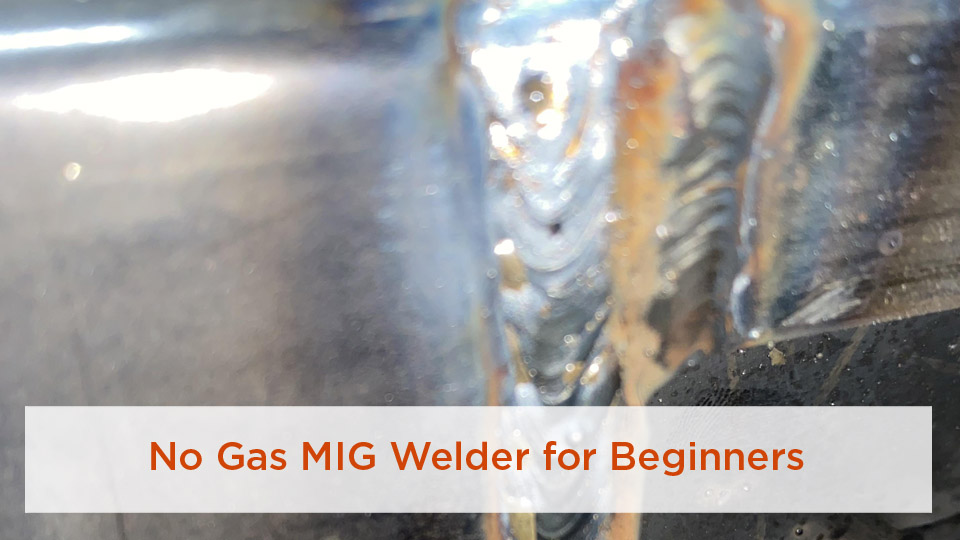
Photo by Instructables
Thin sheet is unforgiving because it has little mass to absorb and spread heat. Excess heat can cause burn-through, edge collapse, warping, and a wide heat-affected zone. Too little heat or wire feed can produce a cold, convex bead with poor fusion. Your goal is a stable arc, a small puddle, and the minimum weld metal needed for the joint.
Key Takeaways
- Use your welder’s door chart or manual as the starting point and test on scrap of the same material, thickness, and joint type.
- For light-gauge mild steel, .023- or .024-inch ER70S-6 solid wire usually gives better low-heat control than larger wire.
- Keep butt-joint gaps as small and consistent as possible; a gap concentrates heat on unsupported edges.
- Use straight, brief tacks or stringer stitches rather than a long continuous bead or weaving motion.
- Short-circuit transfer is useful for thin steel, but it is not recommended for aluminum. Aluminum normally requires spray or pulsed-spray transfer.
At a Glance
| Time Required | About 30–90 minutes for a small joint, including setup, scrap testing, welding, cooling, and inspection |
| Difficulty | Intermediate; beginners should practice on matching scrap before touching the finished part |
| Tools Needed | MIG welder, correct wire and gas, contact tip, clamps, cleaning tools, welding helmet, safety glasses, gloves, protective clothing, and optional copper backing bar |
| Cost | Low consumable cost if you already own the welder and PPE; actual cost varies with gas, wire, tips, cleaning supplies, and scrap material |
Why Thin Metal Burns Through So Easily
Thin metal is often described as sheet below 1/8 inch, but the difficulty rises sharply as you move toward 20-, 22-, and 24-gauge material. The sheet has less metal available to absorb arc energy, so its edges can reach melting temperature almost immediately.
Burn-through usually comes from several factors working together:
- Excess voltage or amperage: The puddle becomes too wide or forceful for the sheet.
- Wire speed that is too high: On a constant-voltage MIG machine, higher wire speed generally raises welding current and can add excessive heat.
- Travel that is too slow: Lingering over one area allows heat to accumulate.
- A large joint gap: Unsupported sheet edges melt before filler metal bridges the opening.
- Long trigger time: A continuous bead keeps heating the same panel after it has already become hot.
- Oversized wire: Larger wire may require more current to run smoothly than very light sheet can tolerate.
- Poor contact-tip-to-work distance: An inconsistent or excessive stickout can make the arc unstable and harder to control.
On 20- to 24-gauge sheet, fit-up is part of your heat control. Even a small gap leaves unsupported edges that can disappear as soon as the arc reaches them.
Tools and Materials for MIG Welding Thin Metal
You do not need the largest MIG machine in the shop, but you do need a machine with stable low-end output and controls that let you match wire speed and voltage to light sheet.
- MIG welder: Use a machine rated for the thickness you plan to weld. Check the manufacturer’s minimum material rating and setup chart.
- Steel wire: For most light-gauge mild steel, .023- or .024-inch ER70S-6 solid wire is a practical choice. Some machines can use .030-inch wire successfully on approximately 18-gauge and thicker material.
- Aluminum wire: Use an aluminum filler compatible with the base alloy, commonly ER4043, ER4943, or ER5356 where appropriate. Aluminum wire normally needs a spool gun, push-pull gun, or another feeding system designed for soft wire.
- Shielding gas: A 75% argon and 25% CO2 mixture is commonly used for short-circuit MIG welding mild steel. Aluminum normally uses 100% argon. Stainless steel requires a gas and filler combination suited to the alloy and procedure.
- Contact tip and liner: Match the tip to the wire diameter and keep the wire path clean. Aluminum setups may require a suitable liner, drive rolls, and gun arrangement.
- Cleaning tools: Use degreaser, clean abrasives, and material-dedicated brushes. Keep a stainless steel brush reserved only for aluminum.
- Clamps and fixtures: Use enough clamps to hold fit-up without forcing the panel into a stressed position.
- Backing bar: A tightly clamped copper or aluminum bar can support the puddle and draw heat from the joint.
- PPE: Wear safety glasses, a properly adjusted welding helmet, flame-resistant clothing, welding gloves, and closed leather footwear.
Warning: Do not weld painted, galvanized, plated, unknown, or solvent-contaminated metal until you have identified the coating and controlled the fume hazard. Zinc oxide from galvanized steel can cause metal fume fever. Use effective ventilation or local exhaust, keep your head out of the plume, and use respiratory protection only when it has been selected for the hazard and properly fitted.
Products Worth Considering

PRE-CUT WELDING COUPONS: 2 x 4 in mild steel plates are sized for bead practice, TIG, MIG, stick, gas welding, and small fabrication work without cutting sheet stock.

6061 Aluminum Plate: Comes with 12pcs aluminum sheets, size - 2”x 4”x 1/8”(0.118") / 50 x 100 x 3 mm
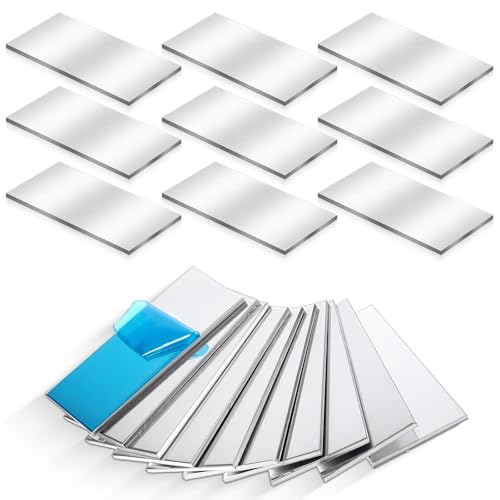
Detailed Dimensions with Ample Quantity: Our package includes 20 pieces of aluminum sheet welding kit, each crafted to precise dimensions of 2 x 4 inches (5 x 10 cm) with a thickness of 1/8 inches (3 mm). These plates are perfect for tasks demanding precision, such as laser cutting and professional welding, delivering consistent results every time.
Choose the Right MIG Setup for the Material
Products Worth Considering

ER308L WIRE: A low-carbon stainless steel wire engineered to minimize intergranular carbide precipitation. This enhances corrosion resistance without the need for stabilizers, making it ideal for critical applications.

E308LFC-O FLUX CORE WIRE: E308LFC-O is a stainless steel welding wire featuring flu core inside, which is used to stabilize the arc, improve the operating performance and play a protective role.

E71T-GS GASLESS FLUX CORE WIRE: This AWS E71T-GS self-shielded flux-cored wire delivers smooth, stable welding without external shielding gas. It offers excellent arc stability, consistent feedability and reliable performance, allowing users to produce clean welds with minimal setup work. Its advanced flux formulation enables welding over light rust and mill scale for improved everyday practicality.
Thin Mild Steel
Thin mild steel is the easiest material covered in this guide. Use direct-current electrode-positive polarity for solid-wire MIG unless your machine or consumable instructions specify otherwise. Install .023- or .024-inch ER70S-6 wire, use the matching contact tip, and connect the shielding gas recommended by the machine manufacturer.
Short-circuit transfer is commonly used because the wire repeatedly contacts the puddle and transfers small amounts of metal at relatively low average heat. You may not have a separate “short-circuit” switch. On many compact welders, the recommended low-voltage solid-wire settings naturally operate in this mode.
Thin Stainless Steel
Thin stainless can also be welded in short-circuit transfer, but you must match the filler wire and shielding gas to the stainless alloy and the service conditions. Stainless welds are sensitive to contamination, excessive heat tint, and poor shielding. Use stainless-dedicated brushes and abrasives, follow the filler manufacturer’s instructions, and avoid treating mild-steel settings as interchangeable.
Thin Aluminum
Aluminum requires a different approach. Its oxide layer must be removed with clean, dedicated tools, and its soft wire needs an aluminum-capable feeding system. Use 100% argon unless the equipment or qualified procedure specifies another gas.
Do not use conventional short-circuit transfer for aluminum where strength or appearance matters. According to Miller’s aluminum MIG guidance, short-circuit transfer can produce poor fusion and crack-prone welds. Conventional aluminum MIG normally uses spray transfer, while pulsed MIG lowers average heat and makes thin material easier to control.
Note: A small steel-capable hobby MIG welder is not automatically suitable for thin aluminum. Confirm that the machine supports the required transfer mode, wire-feeding equipment, amperage range, and base-metal thickness.
How to Set a MIG Welder for Thin Sheet Metal
There is no single voltage and wire-speed combination that works on every welder. Two machines displaying the same numbers may behave differently because of their output design, inductance, gun length, wire, gas, power supply, and calibration.
- Measure the material. Do not guess the gauge. Use a sheet-metal gauge or caliper and identify both the material and coating.
- Read the machine chart. Select the row that matches the material, thickness, wire diameter, gas, and joint position.
- Set gas flow according to the manual. Use enough flow to shield the puddle without creating turbulence. Drafts, nozzle size, joint position, and gun design affect the required flow.
- Test on matching scrap. Use the same material, thickness, joint gap, position, and backing arrangement as the real part.
- Tune one control at a time. Change voltage or wire speed in small steps, then repeat the same tack or short bead.
A stable short-circuit arc on steel often has an even, crisp crackle. Sound is useful, but it is not a substitute for checking bead shape, fusion, penetration, and the reverse side of the test coupon.
Pro Tip: Write down the final voltage, wire speed, gas, wire, stickout, and joint details after a successful scrap test. That record is more useful than a generic setting copied from another welder.
Techniques That Prevent Burn-Through
Keep the Fit-Up Tight
Cut and shape the pieces so the joint closes without a large gap. Do not bevel 20- to 24-gauge sheet as a routine step. Beveling removes edge material and can make the joint easier to melt away.
For a cosmetic butt joint, aim for a small, even gap only if your chosen repair procedure calls for one. When appearance and access permit, a lap joint or plug-welded flange may be more forgiving because it gives the arc more metal to absorb heat. Follow the vehicle manufacturer’s repair procedure when working on collision panels.
Use a Push Angle and Short, Steady Stickout
Hold the gun with a modest push angle, generally about 5–15 degrees in the direction of travel. A push technique directs the arc toward the cooler leading edge of the joint and gives you a clearer view of the puddle.
Keep the contact-tip-to-work distance short and consistent according to the wire and machine instructions. Do not let the gun drift farther away as you move. Excessive stickout can reduce arc stability and make starting each tack less predictable.
Use Brief Tacks and a Skip Sequence
Start with small tacks spaced around the joint. Check alignment, then place new tacks between the original ones. Continue filling the spaces in several passes rather than running a long bead from one end to the other.
Move to a distant part of the panel after each tack or short stitch. Do not follow a universal two- or three-second pause. The required cooling time depends on panel size, thickness, fixturing, ambient temperature, and how much heat is already in the work.
Use Straight Stringer Stitches
When a short bead is suitable, travel in a straight line and keep it as short as the joint permits. Avoid a zigzag or weave. Weaving increases the time the arc spends over the sheet and widens the heated area.
Use the fastest travel speed that still produces fusion and a controlled bead profile. Moving too slowly creates a wide, overheated puddle. Moving too quickly can leave a narrow, convex bead with poor tie-in.
Clamp a Backing Bar Behind the Joint
A copper or aluminum backing bar helps draw heat away and supports molten metal if the edge begins to open. Clamp it tightly to the back of the joint. A loose bar with an air gap will not absorb heat as effectively.
Copper is especially useful for closing a small burn-through hole because ordinary steel filler does not readily fuse to it. The bar supports the new filler while you rebuild the missing edge with brief tacks.
Step-by-Step Guide to MIG Welding Thin Metal
Step 1: Identify and Prepare the Metal
Confirm whether the part is mild steel, stainless steel, aluminum, galvanized steel, or another coated material. Remove oil, adhesive, seam sealer, paint, rust, and oxide from the weld zone. Allow flammable cleaners to evaporate completely and remove their containers from the hot-work area before striking an arc.
For mild steel, clean both sides of the joint where practical. For aluminum, remove grease first and then brush the oxide with a clean stainless steel brush reserved for aluminum. Do not use a carbon-steel brush on aluminum.
Step 2: Fit and Clamp the Joint
Trim the pieces carefully so they sit in their intended position without being forced. Use enough clamps or fixtures to maintain alignment. Check the back of the joint for wiring, trim, insulation, seam sealer, fuel lines, coatings, or other materials that sparks and transferred heat could ignite.
Place a copper backing bar behind a vulnerable butt joint or existing hole when access allows.
Step 3: Install the Correct Wire, Tip, Gas, and Polarity
For light-gauge mild steel, install .023- or .024-inch ER70S-6 solid wire and the matching contact tip. Connect the shielding gas and set polarity as specified by the wire and welder manufacturer.
Do not assume flux-core and solid wire use the same polarity. Do not assume a steel MIG setup can feed aluminum wire correctly.
Step 4: Dial In the Arc on Scrap
Start with the exact chart setting for your machine. Reproduce the real joint on scrap and make several tacks. Look for a flat or slightly crowned bead with clean tie-in, minimal spatter, and no holes.
- If the wire repeatedly hits the work and pushes the gun back, increase voltage slightly, reduce wire speed slightly, or correct the stickout according to the machine instructions.
- If the puddle becomes wide and the edge collapses, reduce heat input, shorten trigger time, increase travel speed, or improve fit-up.
- If the bead sits high with weak toe fusion, the setting may be too cold or travel may be too fast.
Step 5: Place Initial Tacks
Place small tacks at intervals along the joint, starting where alignment matters most. Alternate sides and positions rather than working continuously in one direction. Check the panel after every few tacks because heat shrinkage can pull the joint out of line.
Keep the gun angle, stickout, and starting distance consistent. A tack should fuse both edges without becoming a large mound that must later be ground away.
Step 6: Fill the Gaps in Stages
Add new tacks between the existing ones. Keep moving to cool areas of the joint. On very light automotive sheet, a seam is often completed as a series of overlapping or nearly touching tacks rather than one continuous one-inch bead.
Allow the panel to lose accumulated heat between rounds. Do not weave the gun, and do not keep adding metal simply to make the bead look wider.
Step 7: Inspect and Finish the Weld
Inspect the face and reverse side where accessible. Look for pinholes, missed edges, cracks, porosity, undercut, excessive reinforcement, and areas where the sheet has pulled out of shape.
Dress the weld only as much as the application requires. Grinding creates more heat and can thin the surrounding sheet. Use light pressure, keep the abrasive moving, and stop before the base metal becomes noticeably thinner.
For an exhaust or other leak-sensitive component, use the test method specified for that system. Never pressurize a part beyond its rated test pressure, and never apply leak solution to a hot weld.
How to Repair a Burn-Through Hole
If a hole appears, release the trigger immediately. Continuing to weld at the edge normally makes the opening larger.
- Let the area cool and clean away oxidized or contaminated metal.
- Reduce the cause of excess heat. Check the setting, stickout, travel speed, and nearby joint gap.
- Clamp a copper backing bar behind the hole if possible.
- Start a brief tack on solid metal beside the edge rather than firing directly into the center of the hole.
- Let the tack cool, then add another tack from the opposite side.
- Build inward in small steps until the opening closes.
- Inspect both sides and dress the repair carefully.
Note: If the surrounding metal keeps crumbling, it may be rust-thinned or contaminated beyond a reliable repair. Cut back to sound metal and install a properly fitted patch instead of stacking filler over weak sheet.
Troubleshooting Thin-Metal MIG Welds
| Problem | Likely Causes | What to Change |
|---|---|---|
| Burn-through | Too much heat, slow travel, long trigger time, large gap, hot panel, or oversized wire | Reduce heat input, use shorter tacks, move faster, improve fit-up, allow more cooling, or add a backing bar |
| Wire stubs into the work | Voltage too low, wire speed too high, excessive stickout, or poor electrical connection | Check the work clamp and stickout; tune voltage and wire speed in small steps |
| High, narrow bead | Insufficient heat, travel too fast, or poor toe fusion | Increase heat slightly or slow travel enough to achieve tie-in without overheating the sheet |
| Excessive spatter | Unbalanced voltage and wire speed, dirty metal, poor gas coverage, polarity error, or excessive stickout | Verify polarity, clean the joint, check gas delivery, shorten stickout, and retune the arc |
| Porosity or pinholes | Contamination, wind, blocked nozzle, gas leak, insufficient gas, or excessive gas turbulence | Clean both sides, shield the area from drafts, inspect the nozzle and hoses, and set gas flow according to the manual |
| Panel warping | Long welds, concentrated sequence, slow travel, too many large tacks, or excessive grinding heat | Use smaller tacks, spread the sequence around, allow cooling, improve fixturing, and grind lightly |
| Lack of fusion | Setting too cold, travel too fast, poor gun angle, contamination, or unsuitable aluminum transfer mode | Correct the setup, clean the joint, confirm material compatibility, and test the revised parameters on scrap |
Comparing Heat-Control Techniques
| Technique | Best For | Advantages | Limitations | When to Use It |
|---|---|---|---|---|
| Machine-chart starting settings | All materials | Matches the specific welder and consumable more closely than generic numbers | Still requires scrap testing and fine adjustment | Every setup change |
| Short-circuit transfer | Thin mild steel and some stainless procedures | Low average heat and good positional control | Not recommended for aluminum and can lack fusion when misadjusted | Sheet steel, body panels, light tubing, and similar work |
| Progressive tack or skip sequence | Large, distortion-sensitive panels | Spreads heat and lets the panel cool between welds | Slower than a continuous bead | Auto-body patches, thin enclosures, and long seams |
| Straight stringer stitches | Joints that can tolerate a short bead | Limits dwell time and heated width | Requires steady travel and correct fit-up | Short seams and light tubing |
| Copper backing bar | Thin butt joints and small burn-through repairs | Supports the puddle and conducts heat away | Requires access to the reverse side and tight contact | Ultra-thin sheet, edges, gaps, and pinhole repair |
| Pulsed MIG | Thin aluminum and production work where supported | Maintains spray transfer with lower average heat and reduced burn-through risk | Requires a capable machine and correct programming | Aluminum sheet and heat-sensitive applications |
Practical Tips for Cleaner, Flatter Welds
- Practice on matching scrap: Material type, thickness, coating, joint design, and position should match the finished part.
- Trim the wire before a restart: A clean, consistent wire extension can improve tack starts.
- Keep the nozzle clean: Spatter buildup can disturb shielding gas and hide the contact tip.
- Support large panels: Flexible sheet can move as the wire contacts it, creating inconsistent arc length.
- Watch the joint edges: Aim so both edges melt together instead of concentrating the arc on one unsupported edge.
- Limit grinding: A small, properly sized weld requires less finishing and leaves more base-metal thickness.
- Stop when the panel gets hot: Do not keep welding simply because the arc still runs. Heat already stored in the panel continues to affect distortion and burn-through.
Safety Considerations
MIG welding creates ultraviolet and infrared radiation, hot metal, sparks, electrical hazards, fumes, gases, and fire risk. Treat even a one-second tack as hot work.
Eye and Skin Protection
Wear safety glasses with side protection beneath the welding helmet. Select the filter shade according to welding current and the helmet manufacturer’s instructions. Under OSHA’s filter-lens table, the minimum shade for GMAW and FCAW is 7 below 60 amps and 10 from 60 through 500 amps. A darker setting may be more comfortable as long as you can still see the joint safely.
Cover exposed skin with flame-resistant clothing and gloves. Thin sheet heats quickly and can remain hot after it looks cool.
Fumes and Coatings
Use local exhaust or suitable mechanical ventilation to remove fumes near the source. Position your head outside the rising plume. Do not use oxygen for ventilation.
Galvanized steel can release zinc oxide, which OSHA identifies as a common cause of metal fume fever. Stainless steel, plated metal, painted surfaces, and unknown coatings may create additional hazards. Follow the coating safety data, workplace exposure assessment, and applicable respiratory-protection requirements.
Fire and Explosion Prevention
Remove combustible materials, inspect the opposite side of the work, and keep suitable fire-extinguishing equipment ready. OSHA requires additional fire-watch precautions when normal controls are not enough to prevent ignition.
Warning: Never weld a sealed container or a drum, tank, pipe, or vehicle component that has held fuel, solvent, gas, or another flammable substance unless it has been prepared under an approved hot-work procedure. Vapors can remain after the liquid appears to be gone.
Electrical and Gas-Cylinder Safety
Keep gloves and work areas dry, inspect leads before use, and attach the work clamp to clean metal as close to the joint as practical. Secure shielding-gas cylinders upright, protect the valve, use the correct regulator, and close the cylinder when the work is complete.
Where Thin-Metal MIG Welding Is Used
- Automotive work: Body patches, floor panels, brackets, noncritical exhaust components, and manufacturer-approved plug welds.
- HVAC fabrication: Steel ductwork, housings, supports, and sheet-metal fittings. Copper refrigeration tubing is normally brazed or soldered rather than MIG welded.
- Home and shop repairs: Lawnmower decks, cabinets, furniture, carts, guards, and light trailer skins.
- Industrial fabrication: Machinery guards, enclosures, cabinets, panels, and light-gauge assemblies produced under an approved procedure.
- Marine fabrication: Aluminum or stainless components when the welder, consumables, process, and operator are suited to the alloy and service environment.
Do not treat a good-looking practice weld as automatic approval for a critical repair. Suspension parts, structural vehicle components, aircraft, pressure-containing equipment, lifting devices, and regulated structures may require an engineered repair, a qualified welding procedure, certified personnel, inspection, or all four.
Welding Codes and Project Requirements
AWS D1.1/D1.1M:2025-AMD1 addresses structural-steel welding used in buildings, bridges, infrastructure, and other work where the code is specified. It is not a general instruction manual for every thin-metal repair.
AWS also publishes D1.3 for structural sheet steel, with supporting forms listed in the AWS free welding resources. Other products may fall under a different AWS code, manufacturer repair manual, building code, transportation rule, contract specification, or jurisdictional requirement.
Before welding a load-bearing or safety-critical component, identify the governing requirement instead of choosing a code solely because the material looks thin.
Conclusion
Knowing how to MIG weld thin metal without burning through comes down to controlling the entire setup, not just lowering one dial. Use small wire for light-gauge steel, follow your machine’s chart, test on matching scrap, maintain tight fit-up, keep a short and steady stickout, and distribute brief tacks or stringer stitches around the joint.
A copper backing bar can give you extra control on delicate edges and small holes. Most importantly, separate steel guidance from aluminum guidance: short-circuit transfer works well for many thin-steel jobs, while aluminum generally needs spray or pulsed-spray transfer and an appropriate wire-feeding system.
Take your time during setup and cooling. A few extra scrap tests are faster and cheaper than cutting out a warped panel or rebuilding a hole after the joint has overheated.
Frequently Asked Questions
What wire size is best for MIG welding thin metal?
For most light-gauge mild-steel sheet, .023- or .024-inch ER70S-6 solid wire provides good low-amperage control. Some machines can use .030-inch wire effectively on approximately 18-gauge and thicker steel. Use the wire range approved for your welder and test it on matching scrap.
How should I set my MIG welder for thin metal?
Start with the voltage and wire-speed settings printed on your welder’s door chart or listed in its manual for the exact material, thickness, wire, and gas. Reproduce the joint on matching scrap, then tune in small steps until the arc is stable and the weld has clean fusion without edge collapse.
Can I MIG weld thin aluminum without burning through?
Yes, but the machine must support aluminum wire feeding and the required transfer mode. Use clean, compatible filler wire, 100% argon, fast controlled travel, and spray or pulsed-spray transfer. Conventional short-circuit transfer is not recommended for aluminum because it can produce poor fusion.
Why do I keep burning through thin sheet metal?
Common causes include excessive heat, slow travel, long trigger time, a large joint gap, accumulated panel heat, oversized wire, and poor gun control. Improve fit-up, shorten each tack or stitch, move to cooler areas, use a backing bar, and retest the settings on scrap.
Should I leave a gap when MIG welding thin sheet?
Keep the fit-up as tight and consistent as the repair procedure allows. A wide or uneven gap leaves unsupported edges that burn away easily. If a specified gap is required, reproduce it on your scrap test and use a backing bar where practical.
Can I use gasless flux-core wire on thin metal?
Some flux-core machines are rated for thin sheet, but self-shielded wire generally creates more spatter and can be harder to control on cosmetic 20- to 24-gauge panels. For clean indoor body-sheet work, small-diameter solid wire with shielding gas is usually easier to tune and finish.
Is MIG or TIG better for thin metal?
MIG is fast and practical for thin-steel repairs, especially when the joint will be finished afterward. TIG gives the operator direct control over arc heat and filler addition, which can help with precise stainless or aluminum work. The better process depends on the material, access, appearance, required strength, and operator skill.
Sources
- Miller: Successfully Welding Sheet Metal with MIG and TIG — wire size, fit-up, push technique, skip welding, and backing bars
- Miller: MIG Welding — Setting the Correct Parameters — effects of voltage, wire speed, travel speed, and shielding gas
- Miller: MIG Welding Aluminum — Important Questions and Best Practices — aluminum feeding systems and transfer modes
- OSHA 29 CFR 1910.133: Eye and Face Protection — minimum filter-lens shades for GMAW and FCAW
- OSHA: Welding, Cutting, and Brazing Hazards and Solutions and 29 CFR 1926.352 — fumes, radiation, electrical hazards, burns, and fire prevention
- AWS D1.1/D1.1M:2025-AMD1 and AWS D1.3 resources — structural-steel and structural-sheet-steel code context