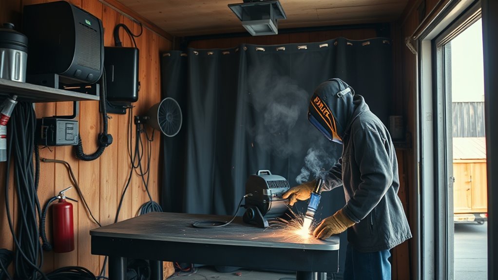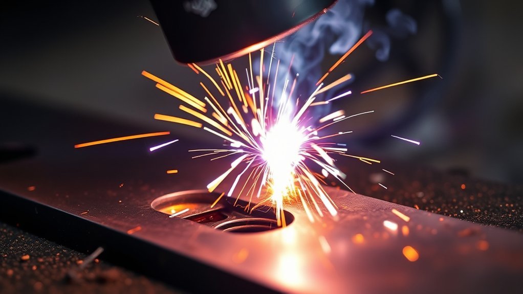
A MIG weld burns through sheet metal when the arc and puddle put heat into the joint faster than the thin base metal can carry it away. The usual causes are settings that are too hot, slow travel, a long arc, wide gaps, repeated welding in one area, or metal that has been ground thinner than expected. Dirty metal can also make the arc less stable and lead you to dwell too long.
Quick Answer
To stop MIG burn-through, start with the machine’s chart for the exact metal thickness, wire, and gas. Lower voltage and wire feed in small, matched steps, keep a short contact-tip-to-work distance, move steadily, and use short skip welds. Tight fit-up and a copper backing bar make thin sheet much easier to control.
Key Takeaways
- Burn-through is mainly a heat-control problem, not simply a lack of welding skill.
- On a typical constant-voltage MIG welder, wire feed speed strongly affects amperage while voltage affects arc length and bead shape.
- A .023- or .025-inch solid wire often gives better control on thin mild steel when the machine and wire manufacturer allow it.
- Fast, straight travel, a small puddle, tight fit-up, and skip welding reduce local heat buildup.
- A copper or aluminum backing bar supports the puddle and helps pull heat away from the joint.
- Test every change on scrap of the same material and thickness before welding the final part.
At a Glance
| Time Required | About 15-30 minutes to inspect, set up, and test; repairing an existing hole may take longer |
| Difficulty | Beginner to intermediate; safety-critical or structural repairs require a qualified procedure and welder |
| Tools Needed | MIG welder, matching wire and contact tip, shielding gas when required, clamps, cleaning tools, scrap metal, PPE, and optional copper or aluminum backing bar |
| Cost | About $0-$40 in extra consumables or backing material if you already own the welder and required PPE |
Key Causes of Burn-Through in MIG Welding
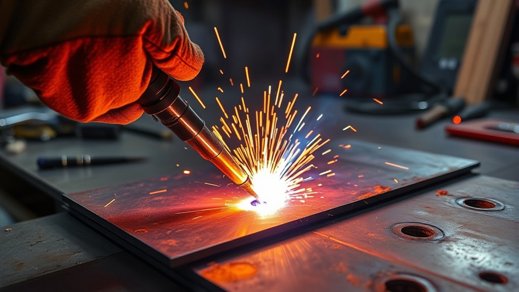
Burn-through means the weld penetrates completely through the base metal and leaves a hole or a sagging area. It is especially common on thin sheet because there is little metal available to absorb and spread the arc’s heat. Miller identifies excessive heat as the main cause and recommends reducing voltage or wire feed speed and increasing travel speed when appropriate.
| What You See | Likely Cause | First Correction |
|---|---|---|
| The puddle suddenly drops through | Voltage or wire feed is too high, travel is too slow, or the joint is already heat-soaked | Stop, let the panel cool, and reduce heat in small steps |
| The hole starts at a joint gap | Poor fit-up leaves no metal bridge to absorb heat | Re-clamp the parts, close the gap, or use a backing bar |
| The bead becomes wide and flat before failure | Travel is too slow or the arc remains in one place too long | Move faster in a straight line and keep the puddle small |
| Only a ground or repaired area burns through | The sheet is thinner there than the machine setting assumes | Treat the thinnest section as the true material thickness |
| The arc is erratic and the puddle is hard to read | Contamination, poor work-clamp contact, inconsistent wire feeding, or excessive stick-out | Clean the joint and clamp point, then inspect the gun and wire feed |
Slow travel speed makes the problem worse because the arc stays over one area and builds a wide, overheated puddle. Excessive weaving has the same effect. Poor joint fit-up is another major cause: even a small open gap in very thin steel removes the heat sink that the surrounding metal would normally provide.
Dirty metal is usually an indirect cause rather than the main source of burn-through. Oil, paint, rust, mill scale, or a weak work-clamp connection can make the arc unstable, create porosity, and tempt you to pause over the joint. Over-grinding is more direct because it physically reduces the sheet thickness. Proper metal preparation techniques can help, but use settings and polarity that match the actual process rather than copying flux-core values to solid-wire MIG.
The goal on thin sheet is not the coldest possible arc. It is the lowest stable setting that still produces fusion while keeping the puddle small and moving.
The Importance of Material Preparation and Cleaning
Good material preparation improves arc stability and makes heat easier to control. Remove oil, grease, paint, rust, and heavy mill scale from the weld zone. Clean the location for the work clamp as well. A wire brush, scraper, grinder, or flap disc may be appropriate, but avoid thinning the sheet while you clean it.
Clean both sides of the joint when possible. Coatings on the back can still burn and create fumes even when the front looks clean. For mild steel, proper cleaning reduces porosity and helps you see the puddle more clearly. Aluminum and stainless steel require material-specific cleaning tools and filler choices; do not assume mild-steel settings apply to them.
A tight joint fit-up is equally important. Clamp the parts so the edges touch consistently, and place tacks close enough to hold alignment without forcing a long continuous bead. Check repaired or ground areas with extra care because they may be thinner than the surrounding panel.
Warning: Welding fumes can be hazardous. Remove paint, solvent residue, and other coatings using a method appropriate for the material, provide effective ventilation or local exhaust, and keep your head out of the fume plume. Galvanized steel produces zinc-containing fume, while stainless steel and some coatings can create additional hazards. Respiratory protection may be required when ventilation and work practices do not control exposure.
Effective Techniques to Prevent Burn-Through
Preventing burn-through requires several small controls working together. Start with the correct process setup, then limit how long the arc stays over any one area. Do not try to solve every problem by turning the machine down until the bead merely sits on top; a weld that looks neat but lacks fusion is not a successful repair.
Products Worth Considering

Do Your Best Work ... Color all your clients impressed with the precision and arc control of the ER70S-6 solid MIG welder wire. You'll love the low splatter whether you're performing single or multi-pass welds. Great for T-joints, butt welds & lap welds.

ER70S-6 MIG WIRE: It's the most common wire of the copper-coated mild steel GMAW (MIG) wires for single or multiple pass welding.
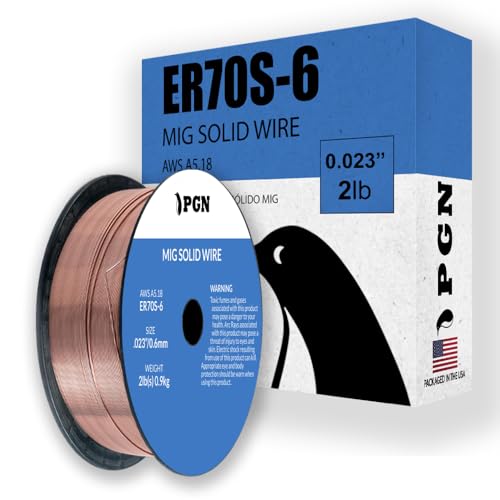
Consistent Welding Performance ... ER70S-6 solid MIG welding wire is designed to provide stable arc characteristics and reduced spatter during single-pass and multi-pass welding applications. Suitable for T-joints, butt joints, and lap joints.
Adjusting Welder Settings
Begin with the chart inside the welder, the owner’s manual, or the wire manufacturer’s data for the exact material thickness, wire diameter, and shielding gas. On many constant-voltage MIG machines, increasing wire feed speed raises amperage and deposition, while voltage changes arc length and bead shape. Adjust the two controls in small steps so the arc remains crisp and stable.
For thin mild steel, a .023- or .025-inch solid wire often operates more comfortably at lower current than larger wire. Miller lists .023-inch wire for roughly 30-130 amps as a general selection range, but the machine’s own chart takes priority. Install the contact tip and drive-roll groove that match the wire size.
Short-circuit transfer is commonly used for thin steel. Keep the contact-tip-to-work distance consistent; about 3/8 inch is a common short-circuit target, while manufacturer guidance may allow a wider range. The original fixed 1/2-inch rule is therefore better treated as an upper-end reference rather than a universal setting.
Use a smaller wire diameter and systematic troubleshooting when the welder’s approved chart supports it. If the arc stubs into the work, the voltage may be too low for the selected wire feed. If the arc becomes harsh, erratic, or washes the puddle too wide, the voltage may be too high. Change one variable at a time and record the result.
Optimizing Travel Speed and Gun Technique
Travel speed controls how long the arc heats each section of the joint. Moving too slowly creates a wide puddle and can cause burn-through. Moving too fast can produce a narrow bead with poor tie-in or lack of fusion. Use the fastest straight-line travel that still keeps the bead tied into both edges.
- Use a small push angle: A 5- to 15-degree push angle generally gives good visibility and can reduce penetration compared with dragging the gun.
- Keep the arc on the leading edge: Do not let a large puddle run ahead of the wire.
- Avoid wide weaving: Side-to-side motion increases dwell time and heat on thin sheet.
- Watch puddle size: If it becomes wider than the thin section you are joining or begins to sag, stop and let the metal cool.
- Keep stick-out consistent: Large changes in contact-tip-to-work distance change current and shielding behavior.
Using Tack, Skip, and Stitch Welding
Short welds help only when they are placed in a sequence that spreads heat. Repeatedly stacking hot tacks in the same area can still blow a hole.
- Place small tacks at several points to lock the joint in alignment.
- Weld a short section at one end, then move to a distant, cooler area.
- Alternate sides or locations instead of progressing continuously along the seam.
- Allow enough cooling time that the next tack does not instantly remelt a large soft area.
- Connect the short sections only as much as the joint design requires.
On non-structural sheet-metal seams, skip or stitch welding also reduces warping. A continuous bead is not automatically better; the required weld length and spacing should follow the design, repair procedure, or applicable welding specification.
Using Tight Fit-Up and a Backing Bar
Close gaps before welding whenever possible. If a gap cannot be eliminated, reduce it with careful fitting rather than trying to bridge it with a large, hot puddle. Clamp the panel firmly so it cannot spring apart as it heats.
A copper or aluminum backing bar can be clamped tightly behind the joint. The bar supports the molten puddle and conducts heat away from the sheet. Copper is popular because steel weld metal does not readily fuse to it under normal sheet-metal MIG conditions. Keep the backing surface clean and in full contact with the work.
Pro Tip: Make a test coupon with the same joint type, gap, material, coating condition, and thickness as the real part. A flat bead on clean scrap does not prove the settings will work across a gapped butt joint.
Best MIG Settings for Thin Metal
There is no single voltage and wire-speed setting that is correct for every 18-, 20-, or 22-gauge panel. Output varies by welder design, input power, wire chemistry, gas, polarity, joint type, position, contact-tip-to-work distance, and actual sheet thickness. Use the manufacturer’s chart as the starting point, then tune on matching scrap.
| Variable | Practical Starting Approach | Signs It Needs Correction |
|---|---|---|
| Wire diameter | Use .023 or .025 inch for thin mild steel when approved by the welder and filler manufacturer | Larger wire may be difficult to run smoothly at the low output the sheet needs |
| Voltage and wire feed | Start at the chart value or low end of the approved range; reduce in small matched steps if the puddle is too hot | Too hot: wide puddle, undercut, sagging, or a hole. Too cold: stubbing, a tall rope-like bead, or poor toe fusion |
| Transfer mode | Use short-circuit transfer unless the machine’s approved sheet-metal or pulsed program specifies otherwise | An unsuitable high-energy transfer mode can overheat thin sheet quickly |
| Polarity | Follow the wire label and machine manual; most gas-shielded solid MIG wire uses electrode-positive polarity | Wrong polarity can cause an unstable arc, spatter, and poor penetration |
| Shielding gas | Use the gas recommended for the wire and material; for short-circuit MIG, Miller gives 25-35 cfh as a general flow range | Too little flow or drafts cause poor coverage; excessive flow can create turbulence and porosity |
| Contact-tip-to-work distance | Keep it steady, commonly near 3/8 inch for short-circuit transfer, unless the manufacturer specifies otherwise | Excessive or changing distance alters current, arc behavior, and gas coverage |
For 18-gauge sheet metal, begin with the welder’s 18-gauge setting rather than a generic number copied from another machine. Make a one-second tack on scrap, inspect the front and back, and then extend the weld only after the tack shows fusion without a sagging center.
Material matters. Mild-steel guidance does not automatically apply to aluminum or stainless steel. Aluminum usually needs different wire-feeding equipment and gas, while stainless requires the correct filler and shielding-gas recommendation. Use material-specific guidance such as the correct voltage and wire speed for 304 stainless steel rather than reusing a mild-steel setup.
Using a MIG wire-speed and voltage chart is useful only when the chart matches the machine, wire, gas, and metal thickness. Fine-tune from that starting point by reading the puddle and inspecting the bead.
Pro Tip: Mark successful settings on a scrap coupon or shop note. Record the machine, input voltage, wire, gas, joint, material, and thickness so the numbers remain meaningful later.
Products Worth Considering

【Powerful 3-in-1 Welding Machine】BESTMIG FLUX-135 offers robust output with a true current of 135A, capable of welding materials up to 1/8 inch thick. Enjoy versatile functionality with MIG, Lift TIG, and Stick welding capabilities for various metal job.
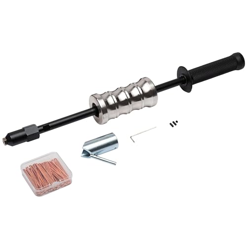
Converts MIG Welder to Stud Welder: Allows your existing MIG welder to perform stud welding for dent repair.

【3 in 1 MultiProcess Welder】: GZ GUOZHI 3 in 1 welder machine. Digital FLUX MIG/ARC/Lift TIG. Unique dynamic characteristics controlling cycle,stable welding arc,lesssplash, nice appearance, high welding efficiency.
How to Correct Burn-Through Issues
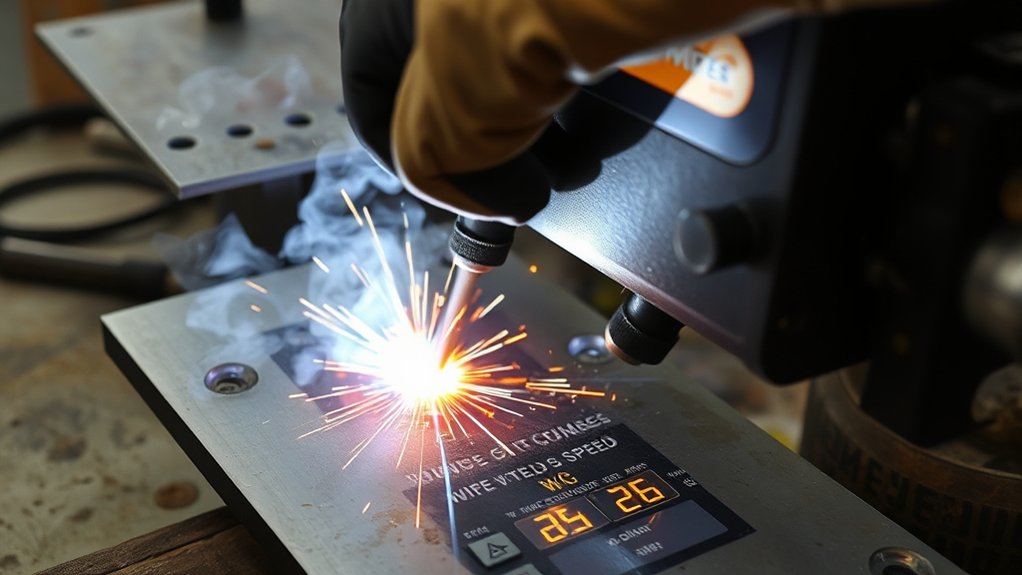
When a hole forms, stop welding. Continuing to pour wire into an overheated opening usually makes the hole larger. Let the panel cool, identify the cause, and correct the setup before attempting the repair.
- Cool and inspect the area: Check whether the hole started at a gap, a thin ground spot, an edge, or an overheated tack.
- Clean back to sound metal: Remove loose, contaminated, or oxidized edges without enlarging the hole more than necessary.
- Clamp a backing plate behind it: Hold clean copper tightly against the back when access allows. It supports the puddle and absorbs heat.
- Reduce heat input: Lower voltage or wire feed speed in small coordinated steps and confirm a stable arc on scrap.
- Start at the edge of sound metal: Place a very short tack that bridges only a small part of the opening.
- Move to the opposite side: Alternate around the hole so no single edge becomes heat-soaked.
- Build inward with cooling pauses: Add small tacks until the opening closes, then allow the repair to cool naturally.
- Dress and inspect the repair: Grind only enough to restore the required profile. Check both sides for cracks, pinholes, lack of fusion, and excessive thinning.
Increasing travel speed also helps when the original failure came from dwelling too long. A copper backing plate is especially useful, but it cannot compensate for settings that are far too hot or a gap that is too wide.
Do not copy a flux-core amperage chart directly to solid-wire MIG. Flux-cored wire may use different polarity, wire diameter, transfer behavior, and voltage ranges. Always return to the chart for the process actually being used.
Note: A cosmetic patch and a structural repair are not the same. Vehicle structures, pressure-containing parts, lifting equipment, frames, roll cages, and other safety-critical components should be repaired only to the applicable manufacturer procedure, welding procedure specification, or code.
Common MIG Welding Issues and Their Solutions
Burn-through can appear alongside other MIG defects. Correctly identifying the symptom prevents you from making the wrong adjustment.
| Problem | Typical Clues | What to Check |
|---|---|---|
| Burn-through | Hole, sagging puddle, or full penetration through the sheet | Heat, travel speed, fit-up, metal thickness, and cooling sequence |
| Lack of fusion or cold lap | Tall bead sitting on the surface with poor tie-in at the edges | Settings may be too cold, travel may be too fast, or the gun angle may be wrong |
| Porosity | Visible pinholes or gas pockets | Dirty metal, drafts, gas leaks, blocked nozzle, wrong flow, or excessive stick-out |
| Excessive spatter | Heavy droplets around the bead and an unstable sound | Voltage-to-wire-feed balance, polarity, work clamp, consumables, contamination, and gas |
| Warping or distortion | Panel pulls, buckles, or changes gap as welding continues | Tack spacing, clamp rigidity, weld sequence, bead length, and total heat input |
A smooth, narrow bead with clear tie-in is a better sign than bead appearance alone, but visual inspection cannot prove the internal quality of a critical weld. When strength matters, follow the required inspection and test method for the job.
What to Check Before You Start Welding Thin Sheet Metal
Use this checklist before striking the arc. It catches many causes of burn-through before they damage the final part.
- Confirm the base metal type and measure or verify its actual thickness.
- Check for hidden coatings, seam sealer, insulation, fuel, wiring, or combustible material on the back side.
- Match the wire diameter, contact tip, drive roll, polarity, and shielding gas to the machine and filler-metal instructions.
- Clean both sides of the joint and the work-clamp contact point when possible.
- Clamp the joint tightly and correct gaps before welding.
- Set voltage and wire feed from the welder’s chart rather than from a different machine.
- Keep the gun angle and contact-tip-to-work distance consistent.
- Plan a tack or skip sequence that spreads heat across the panel.
- Place a copper or aluminum backing bar where access allows.
- Run a test weld on scrap with the same joint and thickness.
Safety Before Welding Sheet Metal
MIG welding exposes you to arc radiation, hot metal, sparks, electrical hazards, noise, and fumes. Wear an appropriate welding helmet, safety glasses, welding gloves, flame-resistant clothing, and closed footwear. Use hearing protection when the task or surrounding work requires it.
Move combustible material away from the work or shield it from sparks and heat. Keep suitable fire-extinguishing equipment ready, and inspect the opposite side of walls, panels, floors, and other hidden areas that can ignite from conducted heat or falling sparks.
Warning: Never weld on a sealed container or on a tank, drum, pipe, or hollow part that held an unknown, flammable, or combustible substance unless it has been properly cleaned, vented, tested, and handled under an approved hot-work procedure. Heating residue can create toxic vapor, fire, pressure, or an explosion.
In a workplace, follow the employer’s hot-work, ventilation, respiratory-protection, and fire-watch requirements. OSHA requires adequate eye and face protection for arc welding and emphasizes controlling fumes through work practices, ventilation, and local exhaust. Outdoor work does not automatically guarantee safe fume control.
How to Tell When Your MIG Settings Are Correct
After a test weld cools, inspect the bead before moving to the final part. A usable thin-sheet setting should produce a controlled bead with consistent width, smooth tie-in at both edges, and enough penetration for the joint without a sagging back side or open hole.
- Too hot: The puddle grows quickly, the bead becomes excessively wide or concave, the edges undercut, or the back side sags.
- Too cold: The wire stubs, the bead is tall and rope-like, spatter increases, or the toes do not fuse into the sheet.
- Travel too slow: The bead is wide and the panel distorts or burns through.
- Travel too fast: The bead is narrow, irregular, or poorly tied in.
- Poor gas coverage: Pinholes, soot, or porosity appear; check flow, leaks, drafts, nozzle blockage, and stick-out.
Change only one variable at a time unless the machine uses a synergic control that links settings automatically. Retest after each change so you know which adjustment improved or harmed the weld.
Frequently Asked Questions
Why is my MIG welder burning through metal?
The joint is receiving more heat than the thin metal can absorb. Common causes include high voltage or wire feed, slow travel, a long or changing contact-tip-to-work distance, an open gap, repeated welding in one hot area, or sheet that has been ground too thin.
How do I weld sheet metal without burning through?
Start with the welder’s chart, use the smallest approved wire for the job, keep the joint tight, and test on matching scrap. Weld in short, separated sections with steady straight travel. Use a copper backing bar when possible and allow the panel to cool between nearby welds.
How do I fix burn-through in welding?
Let the metal cool, clean the damaged edges, and clamp copper behind the hole if access allows. Correct the settings first, then place very short tacks on sound metal around opposite sides of the opening. Build inward with cooling pauses instead of trying to fill the hole in one pass.
Can too much shielding gas cause porosity?
Yes. Excessive flow can create turbulence that pulls surrounding air into the shielding stream. Too little flow, drafts, leaks, or a blocked nozzle can also cause porosity. Use the wire and machine manufacturer’s recommended flow and verify gas delivery at the gun.
Does a copper backing plate stop MIG burn-through?
It helps by supporting the puddle and carrying heat away from the sheet, but it does not correct settings that are far too hot. The copper must sit clean and tight against the back of the joint to work well.
Is stitch welding better for thin sheet metal?
Stitch or skip welding is often better because it distributes heat instead of concentrating it along one continuous bead. Move between separated areas and allow cooling time. The weld length and spacing still need to match the joint’s design requirements.
What wire size is best for MIG welding thin sheet metal?
For thin mild steel, .023- or .025-inch solid wire is a common choice because it can run smoothly at lower current than larger wire. Confirm that the welder, liner, drive roll, contact tip, shielding gas, and filler-metal instructions support the selected size.
Should I lower voltage or wire speed first?
Use the machine’s chart and adjust in small steps. Wire feed speed strongly affects amperage on a typical constant-voltage MIG welder, while voltage affects arc length and bead shape. If the weld is too hot, reduce the appropriate setting without letting the arc become unstable, and retest on scrap.
Sources
- Miller Electric: Successfully Welding Sheet Metal with MIG and TIG — supports fast straight travel, push technique, skip welding, tight fit-up, and backing bars.
- Miller Electric: MIG Welding—Setting the Correct Parameters — supports the relationship among material thickness, wire size, wire feed, voltage, travel speed, and burn-through.
- Miller Electric: What Type of Gas Is Best for MIG Welding in DIY Applications? — supports general short-circuit gas-flow guidance, turbulence, drafts, and contact-tip-to-work distance.
- OSHA: Welding, Cutting, and Brazing—Hazards and Solutions — supports PPE, fume, radiation, burn, electrical, and other welding safety guidance.
- OSHA 29 CFR 1910.252: General Requirements — supports fire prevention, eye protection, protective clothing, hot-work precautions, and container safety.
Conclusion
Preventing burn-through in MIG welding starts with controlled, stable heat. Use the machine’s settings chart, match the wire and gas to the material, keep the joint clean and tight, maintain a short consistent contact-tip-to-work distance, and move fast enough to keep the puddle small.
Practice on scrap with the same thickness and joint before welding the final part. If a hole forms, stop, cool the panel, correct the cause, and rebuild the opening with separated tacks over a backing bar. These steps produce cleaner welds with less distortion and far less frustration.