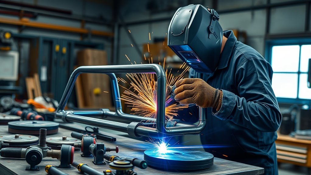
Off-road fabrication puts heavy, repeated loads on every weld. A bumper tab, skid-plate bracket, cage tube, suspension mount, or recovery point may face vibration, impact, twisting, mud, water, and shock. Strong work starts before the arc: identify the material, confirm the vehicle-specific repair rules, choose a suitable process, prepare the joint, protect the vehicle, control heat, and inspect the finished weld before the part carries a load.
Quick Answer
For off-road fabrication, match the welder and filler to the known base metal, joint design, thickness, and load. Clean to bare metal, fit and tack accurately, place the work clamp near the weld, follow vehicle-specific electrical precautions, control heat with a planned sequence, and inspect every weld before use.
Key Takeaways
- Do not select a welder by the amperage number alone. Check the machine’s rated material range, process, input power, duty cycle, and the joint requirements.
- Verify the vehicle, model year, material, coating, and OEM or competition rules before welding a frame, cage, suspension, steering, or recovery component.
- Protect fuel, brake, airbag, wiring, electronic, battery, and high-voltage systems before the arc is struck.
- Clean fit-up, controlled tacks, correct joint preparation, and a balanced weld sequence matter as much as machine settings.
- Visual appearance alone cannot prove a critical weld is safe. Use practice coupons, the required inspection method, and qualified help for high-consequence parts.
At a Glance
| Time Required | About 30 to 90 minutes for setup, preparation, and practice coupons before a small job. Bumpers, cages, mounts, and repairs can take several hours or days. |
| Difficulty | Intermediate for noncritical mild-steel brackets. Advanced and safety-critical for frames, cages, suspension, steering, recovery points, or unknown alloys. |
| Tools Needed | Suitable MIG, TIG, flux-core, or stick welder; correct filler and gas; helmet; safety glasses; gloves; flame-resistant clothing; clamps; grinder; measuring tools; ventilation; fire extinguisher; and matching scrap coupons. |
| Cost | Varies with power supply, machine, shielding gas, PPE, filler metal, abrasives, material, engineering, and inspection. Saving money with an undersized setup is not a safe tradeoff. |
Warning: Do not weld on a fuel tank, sealed container, wheel, pressurized part, or near fuel vapor. Do not weld a frame, roll cage, suspension, steering, recovery, or high-voltage component without the applicable OEM instructions, drawing, rulebook, procedure, qualifications, and inspection. Failure can cause fire, electric shock, loss of control, serious injury, or death.
Choose the Right Welder and Power Supply
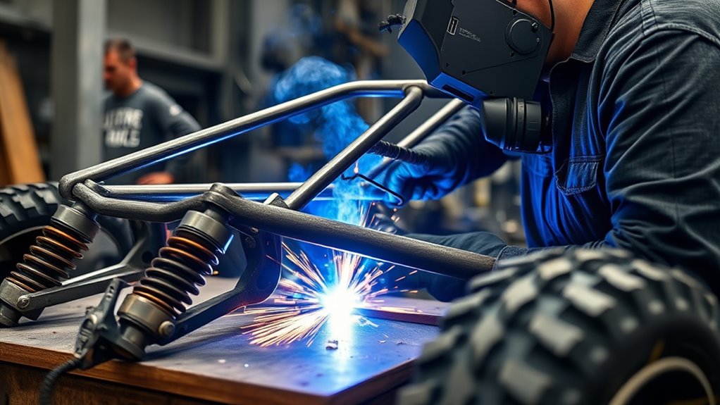
Start with the known metal thickness, joint design, welding position, and risk of the part. A compact 120V MIG machine can be useful for sheet metal, light tabs, and small brackets. Heavier brackets, bumpers, sliders, and repeated fabrication usually call for more output, a higher duty cycle, and a suitable 240V circuit.
Do not treat “140 amp,” “180 amp,” or “200 amp” as a universal thickness rating. Current manufacturer examples show why: Miller rates its 120V Millermatic 142 for mild steel through 3/16 inch, while the dual-voltage Millermatic 211 PRO is rated through 3/8 inch. Those are machine-specific capability claims, not approval for a structural joint. Joint geometry, process, wire, position, fit-up, pass sequence, and required weld quality still control the job.
Compare the machine’s rated output at the input voltage you will use, not only its peak amperage. Check the wire diameter range, polarity options, spool-gun support, process modes, gun rating, and whether the machine is approved for solid wire and the exact flux-cored wire you plan to run.
The duty cycle states how much of a 10-minute period a machine can weld at a listed output before cooling is required. For example, a 30% duty cycle at a stated amperage means up to three minutes of welding followed by seven minutes of cooling under the manufacturer’s test conditions. Compare duty cycle at the output your joint needs.
Input power matters too. Use the receptacle, branch circuit, plug, and extension-cord limits in the owner’s manual. A long or undersized extension cord can cause voltage drop and unstable performance. Never defeat a breaker, thermal shutdown, or grounding provision to keep welding.
Solid wire with shielding gas is clean and controlled in a protected shop. Self-shielded flux-core wire is often more practical outdoors because wind can disturb external shielding gas. Confirm the exact wire’s polarity, thickness range, welding positions, and single-pass or multipass limits, then review these self-shielded flux-core welding tips before relying on it for a vehicle part.
Note: A machine that can deposit metal on a certain thickness is not automatically suitable for a load-bearing weld. The design, procedure, operator qualification, and acceptance criteria determine whether the finished joint is acceptable.
Products Worth Considering
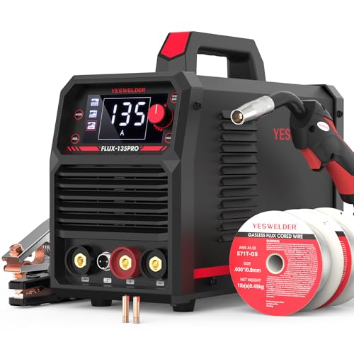
READY OUT OF THE BOX: Start welding immediately! It masterfully handles Gasless Flux Core MIG, Stick, and Lift TIG (Extra Lift TIG torch required). This budget-friendly 3-in-1 machine includes extra E71T-GS .030''&.035'' flux core wires, known for its smooth arc and high feedability. Say goodbye to heavy shielding gas cylinders—perfect for outdoor, windy, or all-position welding.

4-IN-1 MIG Welder: The welder machine offers GAS MIG/Flux Core MIG/Lift TIG/ MMA welding modes (Note: WP-17V TIG torch must be purchased separately). It can easily handle welding stainless steel, carbon steel, and even thicker steel materials, meeting diverse welding requirements.

MULTIFUNCTIONAL: A 4-in-1 welder, capable of Flux Core MIG/Gas MIG/ Stick/Lift TIG (need to purchase extra tig lift torch). This unit caters to a wide range of welding applications and meets your various welding needs.
Protect the Vehicle Before Welding
Whenever possible, remove the part from the vehicle and weld it on a stable bench. This improves access and keeps heat, sparks, and welding current away from fuel lines, brake lines, bearings, wiring, glass, trim, airbags, sensors, and electronic modules.
If the part must be welded on the vehicle, identify the year, make, model, powertrain, and relevant options by VIN, then check the current OEM service or body-repair information. Vehicle makers can require specific battery, airbag, module, coating, and high-strength-steel precautions. A generic internet checklist cannot replace those instructions.
General Motors’ Electrical Best Practices, for example, advises placing the welder work clamp as close as possible to the weld, disconnecting battery negative cables, disabling the airbag system as directed, protecting wiring and electronics from heat and sparks, and disconnecting nearby modules. Other manufacturers may specify a different sequence, waiting period, or additional steps.
- Turn the vehicle off, remove the key or disable passive-start operation, and follow the OEM shutdown procedure.
- Inspect both sides of the weld area for fuel, brake, hydraulic, refrigerant, and electrical lines.
- Shield or remove heat-sensitive parts; do not rely on a welding blanket alone when a line or module is too close.
- Attach the work clamp to clean metal on the same part and as close to the weld as practical.
- Do not place the return-current path through a wheel bearing, driveline bearing, steering joint, suspension component, hinge, or electronic module.
- Route welding leads away from vehicle wiring, control modules, sensors, and high-voltage cables.
- After welding, inspect nearby wiring, hoses, lines, coatings, and modules before reconnecting power.
Warning: Disconnecting a 12V battery does not make a hybrid or electric vehicle’s high-voltage system safe. Orange high-voltage cables and battery components can remain dangerous. NHTSA recommends EV service by a qualified technician with specialized high-voltage training. Do not weld near high-voltage parts until the exact OEM depowering, lockout, verification, and repair procedure has been completed.
Welding Safety Before You Start
Off-road fabrication is hot work. Wear an approved welding helmet with the shade selected for the process and current, safety glasses with side protection, dry welding gloves, flame-resistant clothing, closed leather footwear, and hearing protection when grinding. Protect nearby people with screens or curtains.
Clear the spark path above, below, behind, and on the far side of the work. Remove fuel, oily rags, paper, sawdust, aerosol cans, batteries, upholstery, insulation, and other combustibles. Keep suitable fire-extinguishing equipment ready. OSHA’s welding, cutting, and brazing requirements address fire prevention, ventilation, eye protection, confined spaces, and hot-work controls. A fire watch may be required when sparks can reach hidden or delayed ignition hazards.
Control fumes at the source. Keep your head out of the plume and use local exhaust or other effective ventilation that does not strip shielding gas from the arc. OSHA’s welding-fume fact sheet explains that the base metal, filler, coatings, process, location, and ventilation all affect exposure. Working outside does not automatically make the fumes safe.
Be especially cautious with galvanized steel, stainless steel, painted or plated parts, unknown scrap, undercoating, solvent residue, and confined areas. CDC/NIOSH notes that welding fume can contain hazardous metals and gases and that control measures should reduce exposure. Review the CDC/NIOSH welding-fume guidance before repeated, enclosed, or high-exposure work.
Never weld near chlorinated solvent vapor or on metal that still carries chlorinated cleaner residue. The CDC states that heating metal cleaned with chlorinated hydrocarbons can produce phosgene. OSHA also warns that heated degreasing residues can form hazardous decomposition products. Use only a cleaner approved for the task, follow its safety data, remove all residue, and keep the container and vapor far from hot work.
Warning: Do not weld over brake cleaner, solvent residue, paint, undercoating, zinc, oil, or an unknown coating. Remove the material by a controlled method, identify the hazard, and use effective ventilation. Galvanized steel can produce zinc oxide fume, and chlorinated residue can form highly toxic decomposition products when heated.
Identify the Metal, Coating, and Load Path
Before cutting or welding, identify the base metal and its condition. Mild steel, high-strength steel, cast steel, cast iron, 4130 tubing, stainless steel, and aluminum need different filler choices, heat control, and repair methods. Spark appearance, magnet response, or color is not enough to identify a safety-critical material.
Check drawings, purchase records, stamped markings, OEM service information, and supplier documentation. Measure the actual thickness after removing scale or coating. Do not weld unknown scrap into a recovery point, suspension mount, steering part, cage, or frame repair.
Then map the load path. Ask what force the part carries, where it enters the bracket, how the load reaches the chassis, and where stress can concentrate. A large bead cannot correct a weak tab shape, poor edge distance, an unsupported bracket, a sharp transition, or a weld placed in the wrong load path. Critical design should come from an engineer, tested kit, OEM repair method, approved drawing, or applicable rulebook.
Formal requirements change by application. The current AWS D1.1/D1.1M:2025-AMD1 covers structural steel welding when a project invokes that code. Competition cages may be governed by a current sanctioning-body document such as the FIA’s 2026 Appendix J regulations. Neither source automatically applies to every off-road vehicle, but both show why material, procedure, qualification, fabrication, and inspection requirements must be identified before work begins.
Clean and Prepare the Joint Before Welding
Remove paint, rust, mill scale, oil, grease, undercoating, plating, moisture, and other contaminants from the joint and a suitable area around it. Clean metal gives the arc a stable path, lowers porosity risk, and lets you see whether the weld toes tie into the base metal.
Use an angle grinder, flap disc, scraper, or dedicated wire brush as appropriate for the material. Avoid thinning the base metal or cutting deep grooves beside the joint. Keep separate stainless-steel brushes and abrasives for stainless or aluminum so carbon-steel particles do not contaminate the surface.
For a fuller preparation process, review this guide to cleaning mild steel for welding.
Remove Paint, Rust, and Coatings
Clean both sides of the joint when heat can pull contamination through the root. Remove paint, rust, oil, and grease far enough from the weld to keep them out of the puddle and to expose the full toe area for inspection.
Use a grinder or flap disc for heavy rust, paint, and mill scale, then finish with a suitable brush or clean abrasive. Inspect pits and seams under strong light. If oil film, coating, moisture, or packed rust remains, clean the joint again before fitting it.
If the part is galvanized, plated, or coated, identify the coating, remove it around the weld by an approved method, control the fumes, and plan to restore corrosion protection after the weld cools. Learn more about how to prepare galvanized steel for MIG welding.
Use the Joint Preparation Required by the Design
A bevel can give the arc access to the root of a thick butt joint, but there is no universal “30 to 45 degree” rule for all off-road work. Groove angle, root opening, root face, backing, pass sequence, and allowable penetration depend on the material, thickness, process, position, design, and welding procedure.
Do not assume that every joint over 1/4 inch must receive the same bevel or that a deeper-looking bead proves fusion. Use the drawing, qualified welding procedure specification, OEM repair instruction, or tested joint plan. Practice the exact preparation on matching scrap before welding the final part.
- Measure the bevel, root face, and root opening rather than estimating by eye.
- Keep the prepared edges clean and consistent from end to end.
- Use backing only when the material, joint, and procedure permit it.
- Provide enough access to clean and inspect every pass.
- Remove slag, oxide, and defects before depositing the next pass.
- Do not fill a large uncontrolled gap with weld metal as a substitute for fit-up.
Prepare Backing, Dissimilar Thicknesses, and Tube Joints
When joining different thicknesses, direct heat according to the process and procedure so the thicker member fuses without eroding the thin edge. Copper backing can help on some thin-steel practice joints, but it is not suitable for every material, access condition, or critical weld.
Tube notches should contact closely around the intended joint. A wide gap hidden on the back side can lead to excessive filler, burn-through, or incomplete fusion. Make a dry run with the gun or torch to confirm that you can reach the full joint before final assembly.
Wear a helmet, safety glasses, gloves, hearing protection as needed, and flame-resistant clothing while cleaning, grinding, beveling, and welding. Grinding debris and wire-wheel fragments can injure you before the arc is ever struck.
Fit Up, Tack, and Clamp for Alignment
Good fit-up keeps parts aligned and the root condition consistent. It also prevents you from using weld metal to hide a poor joint. Measure, test-fit, and adjust the assembly until it sits true without forcing the pieces together.
Use clamps, squares, straightedges, magnets, tube notching tools, fixtures, and temporary braces. Recheck the part after clamping because clamps can pull thin plate or tubing out of square.
- Confirm hole locations, centerlines, diagonals, and mounting surfaces before tacking.
- Place tacks in a balanced pattern that controls movement without blocking final access.
- Set tack length and spacing for the part, thickness, restraint, and procedure rather than using one fixed interval.
- Make tacks with the same cleanliness and fusion expected from the final weld.
- Remove and repair cracked, porous, or poorly fused tacks before welding over them.
- Recheck geometry after each group of tacks and before every long weld.
- Support heavy parts so the tack welds are not carrying the assembly’s full weight.
For bumpers, sliders, cages, and chassis fixtures, tack the most rigid reference points first, then verify symmetry and clearance. Check door, body, suspension, driveline, tire, steering, and service access before the assembly becomes difficult to change.
Pro Tip: Mark centerlines and record diagonal measurements before the first tack. Recheck the same measurements after each major weld sequence so distortion is found while it can still be corrected safely.
Control Heat and Prevent Warping
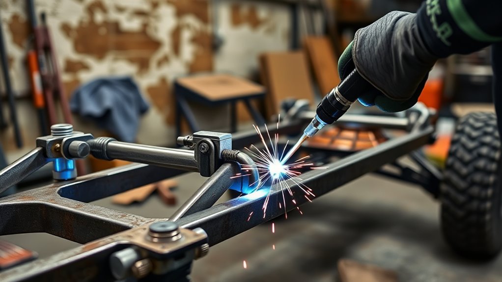
Set voltage, wire feed, amperage, gas, polarity, and travel speed from the machine chart, filler data sheet, or welding procedure, then verify them on matching scrap. Settings that are too cold can cause poor tie-in or lack of fusion. Excess heat can burn through thin material, enlarge the heat-affected zone, damage nearby components, and pull the assembly out of shape.
For MIG welding, keep a steady contact-tip-to-work distance. Solid-wire short-circuit MIG usually uses a shorter wire extension than self-shielded flux core, but the exact range comes from the machine and wire instructions. Changing stickout while moving changes current, arc behavior, and heat at the joint.
Plan the weld sequence before starting. Shorter welds, skip welding, backstepping, alternating sides, and cooling time can distribute shrinkage. Do not place every weld on one side before moving to the other unless the procedure calls for it.
Preheat and interpass temperature are material- and procedure-specific. Do not heat chromoly, high-strength steel, cast material, or a frame with a torch because a generic tip suggested it. Measure and follow the required temperature range when a procedure specifies one. Do not quench a critical weld with water or compressed air unless the approved procedure allows it.
Watch the leading edge of the puddle and both weld toes. A violent arc, rolling puddle, undercut, poor wetting, or unstable sound can point to a problem with settings, work angle, travel speed, stickout, polarity, gas coverage, or the work connection. Learn more about shielding-gas coverage and porosity prevention.
A larger bead does not repair poor fit-up, incomplete fusion, a weak load path, or heat-damaged material. Controlled preparation and verified fusion matter more than appearance alone.
Choose Wire, Gas, and Filler Metal
The filler must match the known base metal, joint design, service temperature, strength, corrosion needs, and governing procedure. Do not choose filler only because it is already loaded in the machine.
For many clean mild-steel brackets and tabs, ER70S-6 solid wire is a common MIG choice. It contains more deoxidizers than ER70S-3, but that does not make it a substitute for cleaning. Miller’s mild-steel MIG guide identifies .030-inch ER70S-6 as a useful all-around option and .023-inch wire as a common choice for thinner metal. The correct diameter still depends on the machine and joint.
For mild-steel short-circuit MIG, a 75% argon/25% carbon-dioxide mix is common because it provides a stable arc, good bead shape, and relatively low spatter. Straight carbon dioxide can be economical and can change penetration and spatter. Use only a gas listed for the exact wire, process mode, and procedure. Shielding-gas flow must be set with the correct regulator or flowmeter and adjusted for the nozzle, drafts, and manufacturer’s range.
Self-shielded flux-core wire does not use an external gas cylinder, but it is not one universal product. Read the classification and data sheet for polarity, approved positions, base-metal thickness, storage, and pass limitations. Remove slag completely between passes.
For TIG welding mild steel, ER70S-2 is a common filler, but a procedure may require another classification. For 304 or 304L stainless steel, an ER308L filler is commonly used for similar-metal joints; Lincoln Electric lists its 308L wire for 304/304L stainless steels. Dissimilar stainless-to-carbon-steel joints often require a different filler and shielding plan.
Aluminum filler cannot be selected from appearance alone. Common choices include 4043, 4943, and 5356, but the correct filler depends on the exact base alloy, strength, ductility, corrosion exposure, anodizing, and service temperature. Clean the oxide with dedicated tools and follow the filler manufacturer’s compatibility chart.
Note: Filler suggestions are starting points for noncritical practice, not a welding procedure specification. Chromoly, cages, suspension parts, frames, recovery points, and competition vehicles may require a named filler, process, preheat range, welder qualification, and inspection method.
Products Worth Considering

ER70S-6 MIG WIRE: It's the most common wire of the copper-coated mild steel GMAW (MIG) wires for single or multiple pass welding.

High-quality: ARCCAPTAIN's ER70S-6 mig welding wire .035" meets industry standards(Net Weight: 10lbs), ensuring consistent performance, superior strength. With its smooth feeding and stable welding parameters, you can achieve optimal penetration, high deposition rates, and exceptional overall welding performance.

High-quality: ARCCAPTAIN's ER70S-6 mig welding wire .030" meets industry standards(Net Weight: 10lbs), ensuring consistent performance, superior strength. With its smooth feeding and stable welding parameters, you can achieve optimal penetration, high deposition rates, and exceptional overall welding performance.
Match the Welding Process to the Part
Choose the process for the known material, access, environment, joint, quality requirement, and operator skill. Do not force one machine to cover every part.
| Part Type | Possible Process | Key Caution |
| Noncritical mild-steel tabs and brackets | Solid-wire MIG or suitable flux-core | Confirm material, clean both members, control gaps, and avoid cold lap on small fillets. |
| Bumpers, sliders, and skid mounts | Higher-output MIG, suitable FCAW, or TIG where precision is needed | Use a designed load path, correct groove or fillet size, full access, and the required pass sequence. |
| Roll cages | MIG or TIG as allowed by material and rulebook | Tubing, bends, notches, joint access, process, welder qualification, and inspection must meet the current rules. |
| Suspension arms and steering parts | Engineered and qualified procedure only | Do not guess at alloy, heat treatment, filler, or repairability. Replacement is often safer than an unapproved repair. |
| OEM frame or high-strength body structure | Only the OEM-specified repair process | Heat and weld placement can change strength and crash behavior. Verify by VIN and model year. |
| Aluminum accessory parts | AC TIG or aluminum-capable MIG with a suitable feed system | Identify the alloy, remove oxide correctly, match filler, and control heat and distortion. |
| Exhaust tubing | TIG or MIG | Use compatible filler, purge when required, and prevent burn-through on thin tubing. |
| Field repair on known carbon steel | Suitable self-shielded FCAW or stick | A trail repair may only be temporary. Clean, inspect, and replace or professionally repair the part before normal service. |
Correct amperage is essential when stick welding, but electrode classification, diameter, polarity, position, joint, and machine output also matter. Use this stick welding amperage chart only as a starting reference, then follow the electrode data sheet and procedure.
Plan Weld Access, Position, and Pass Sequence
Make a dry run before final tacking. Confirm that your helmet, hands, gun or torch, filler rod, and cables can reach the entire joint while you keep a stable body position. A cage joint that can only be reached through a narrow blind gap is not ready for final welding.
Rotate a removable part into the easiest safe welding position whenever possible. Out-of-position welding changes puddle control, travel direction, settings, and allowable filler choices. Use only positions approved by the wire, electrode, and procedure.
- Start and stop where craters can be filled and inspected.
- Clean every pass and remove visible defects before covering them.
- Keep each pass within the weave and heat limits of the procedure.
- Do not weld over slag, cracked tacks, porosity, or an arc strike outside the joint.
- Do not grind a structural bead flush for appearance unless the design or repair procedure requires it.
- Mark hot metal and keep people away until the entire assembly has cooled safely.
Inspect and Test Your Welds
Do not judge a weld only by shine, ripple pattern, or bead size. After the weld cools, remove slag and spatter that block the view, then inspect under strong light. Compare the finished joint with the drawing, welding procedure, or acceptance standard that applies.
- Look for cracks at starts, stops, craters, weld toes, and the heat-affected zone.
- Check for undercut, overlap, excessive reinforcement, incomplete fill, or visible lack of fusion.
- Look for porosity, pinholes, worm tracks, and trapped slag.
- Confirm the weld ties into both members and reaches the required length and size.
- Check for arc strikes, excessive grinding, overheating, and damage beside the joint.
- Measure distortion, pulled brackets, changed diagonals, and hole misalignment.
- Inspect the opposite side for heat damage, burn-through, damaged coatings, wiring, hoses, and lines.
Practice coupons can reveal whether your settings and technique are suitable. Use scrap of the same known material, thickness, joint, position, and preparation. Cut-and-etch, guided bend, or break tests can be useful when performed correctly, but a successful coupon does not automatically qualify a production weld or replace the inspection required by a code or rulebook.
Critical parts may require inspection by a qualified welding inspector and nondestructive examination such as liquid penetrant, magnetic particle, ultrasonic, or radiographic testing. The correct method and acceptance criteria must come from the governing procedure or engineer. Do not invent a pass/fail standard after the part is built.
Pro Tip: Keep a labeled failed coupon beside a successful one. Record the material, joint, position, settings, filler, gas, and failure location so the lesson is repeatable instead of based on memory.
Finish, Protect, and Reinspect the Fabrication
Remove slag, sharp spatter, and burrs without thinning the base metal or cutting into weld toes. Do not hide cracks, undercut, or porosity under filler, seam sealer, paint, or powder coat. Repair defects under the approved procedure before applying a finish.
After the assembly has cooled and passed inspection, restore corrosion protection that was removed for welding. Use a coating compatible with the base metal, vehicle maker’s repair instructions, service temperature, and planned topcoat. Keep paint, zinc-rich coating, seam sealer, cavity wax, and undercoating away from any area that still needs welding.
Before reconnecting or starting the vehicle, inspect the work area for tools, hot spots, damaged wiring, melted clips, pinched hoses, open fuel or brake lines, and loose grounds. Reconnect batteries, airbags, modules, and high-voltage systems only in the OEM sequence. Perform any required scan, calibration, leak check, or functional test.
Reinspect the fabrication after its first controlled use and at normal service intervals. Look for cracked paint at weld toes, fretting, loose fasteners, distortion, or contact marks that show the load path is not behaving as expected. Remove the vehicle from service if a safety-critical part shows cracking or movement.
Common Welding Problems and Fixes
Most early off-road welding problems trace back to contaminated metal, poor fit-up, incorrect setup, unstable technique, or a process that does not suit the joint. Use this table to guide testing on scrap, not to approve a critical repair.
| Problem | Likely Causes | Checks and Corrections |
| Porosity | Dirty or wet metal, poor gas coverage, drafts, leaking gas path, damaged nozzle, or excessive stickout | Clean and dry the joint, block drafts without trapping fumes, check the cylinder-to-nozzle gas path, clean the nozzle, and use the specified stickout. |
| Cold lap or lack of fusion | Low heat at the joint, fast travel, poor work angle, heavy scale, excessive stickout, or wrong joint preparation | Return to the approved setup, clean the joint, correct the angle and stickout, verify preparation, and retest on matching scrap. |
| Burn-through | Excess heat, slow travel, thin edge, large gap, or unsuitable wire and process | Tighten fit-up, lower heat within the approved range, shorten weld time, use suitable backing when permitted, or change the wire, process, or machine. |
| Undercut | Excess voltage, fast travel, poor angle, long arc, or failure to fill the toe | Verify settings and stickout, stabilize the work angle, slow only as needed, and watch both toes on a practice coupon. |
| Slag inclusion | Slag left between passes, wrong travel angle, low toe fusion, or a wide uncontrolled weave | Remove all slag, grind defects as allowed, use the wire’s approved technique, and deposit controlled passes with access to both toes. |
| Warping or pulled brackets | Too much continuous heat, weak fixturing, unbalanced sequence, or oversized welds | Improve the fixture, use the planned weld size, alternate locations, shorten welds where allowed, and let the assembly cool naturally. |
| Excess spatter or unstable arc | Wrong polarity, voltage and wire-feed mismatch, poor work connection, dirty metal, worn tip, or inconsistent stickout | Check the wire label and polarity, clean the clamp point, replace worn consumables, return to chart settings, and stabilize gun position. |
| Crack at a tack or crater | Contamination, restraint, unfilled crater, unsuitable filler, or material-related cracking | Stop. Remove the crack completely under the approved repair method, confirm material and filler, correct the cause, and do not weld over it. |
Practice on Scrap Before Your First Build
Before welding an off-road part, practice on scrap from the same known material and thickness. Match the joint type, preparation, position, filler, gas, and backing condition. Flat beads on unrelated plate do not prove you can weld the final tube or bracket joint.
Start with butt, lap, corner, and fillet coupons. Then copy the real part’s gap, bevel, access, and orientation. If both MIG and TIG are available, compare them only after each process is set up with the correct filler, shielding, polarity, and machine range.
After every pass, remove slag or residue and inspect tie-in, penetration evidence, undercut, porosity, crater fill, and distortion. Change one variable at a time so the effect is clear.
Record the machine, input voltage, process mode, material, thickness, wire or filler classification, diameter, shielding gas, flow setting, polarity, voltage, amperage or wire speed, stickout, joint, position, travel direction, and test result. This creates a repeatable shop reference, not a substitute for a qualified WPS.
Note: Plasma-cutter air pressure, such as a 35 PSI setting, is unrelated to MIG or TIG shielding-gas flow. Follow the regulator, flowmeter, machine, torch, and filler instructions for the welding process you are using.
Frequently Asked Questions
Can you make $100,000 as a welder?
Yes, but it is not typical pay for the occupation as a whole. The U.S. Bureau of Labor Statistics reported a May 2025 national median annual wage of about $56,760 for welders, cutters, solderers, and brazers. Six-figure income is more likely with extensive overtime, specialized field work, travel, supervision, inspection, high-risk assignments, or a profitable fabrication business.
What is F1, F2, F3, and F4 in welding?
The meaning depends on the code. In AWS D1.1 discussions, F1 through F4 commonly identify SMAW electrode usability groupings used for welder qualification. ASME Section IX uses F-numbers more broadly to group filler metals for qualification rules. They are not quality grades. Check the exact code edition, WPS, and qualification record before selecting an electrode.
What is the best welder for car fabrication?
For general mild-steel automotive fabrication, a quality dual-voltage MIG machine with enough rated output and duty cycle for the planned thickness is often the most versatile choice. TIG provides more precise control for aluminum, stainless, thin tubing, and some rule-governed work. The best machine is the one that supports the required process, filler, input power, position, and procedure.
What are the seven basic types of welding?
There is no single official list limited to seven. Common process families include gas metal arc welding (MIG/GMAW), gas tungsten arc welding (TIG/GTAW), shielded metal arc welding (stick/SMAW), flux-cored arc welding (FCAW), oxy-fuel welding, plasma arc welding, and laser beam welding. Off-road fabrication most often uses MIG, TIG, flux core, or stick.
Is flux-core welding good enough for off-road fabrication?
A suitable flux-cored wire can work well on approved carbon-steel joints, especially outdoors. It still requires the correct polarity, machine output, joint preparation, position, pass limits, slag removal, and inspection. Do not assume a small self-shielded wire is approved for multipass or safety-critical vehicle work; read its data sheet and the governing procedure.
Should you weld a roll cage yourself?
Only if the current rulebook permits your process and you can meet its material, tube, bend, notch, joint-access, welder, and inspection requirements. A cage is occupant-protection equipment. When any requirement is uncertain, use a qualified cage fabricator and the sanctioning body’s current rules.
Can a 140-amp MIG welder weld 1/4-inch steel?
Do not assume it can from the amperage label alone. Many 120V machines are rated below 1/4 inch in a single pass, while some setups allow limited multipass work under specific conditions. Check the exact machine chart, input voltage, wire, joint, position, and duty cycle. A structural or recovery joint also needs an approved design and procedure.
Should you disconnect the battery before welding on a vehicle?
Follow the exact OEM procedure for the VIN and model year. Manufacturers commonly require disconnecting negative battery cables and may also require airbag disabling, waiting periods, nearby-module disconnection, and a close work-clamp location. Hybrid and EV high-voltage systems require separate trained-technician procedures; disconnecting the 12V battery is not enough.
Conclusion
Strong off-road fabrication comes from a controlled process, not a large bead. Identify the metal and load path, verify the vehicle and rule requirements, select a capable welder and filler, protect the vehicle, clean and fit the joint, plan tacks and weld sequence, control heat, and inspect the result. Practice can build skill on noncritical brackets, but frames, cages, suspension, steering, recovery points, and high-voltage vehicles deserve qualified procedures, inspection, and professional help when the consequences are high.
Sources
- OSHA 29 CFR 1910.252: General Welding Requirements — fire prevention, eye protection, ventilation, confined spaces, and hot-work controls.
- OSHA Welding Chemical Hazards — fumes, coatings, metals, and hazardous decomposition products from residues.
- CDC/NIOSH Welding Fumes — welding-fume exposure and control guidance.
- General Motors Electrical Best Practices — vehicle battery, airbag, module, wiring, work-clamp, and heat precautions during welding.
- Miller: MIG Welding for Mild Steel — wire selection, setup principles, and common mild-steel MIG practices.
- AWS D1.1/D1.1M:2025-AMD1 — current structural-steel welding requirements when invoked by a project.