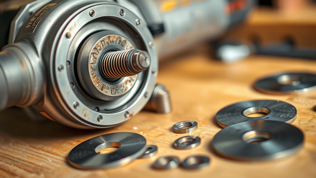
Angle grinder arbor sizes can be confusing because the spindle thread and the hole through a wheel are not always the same measurement. On many U.S.-market grinders, a 5/8-11 threaded spindle is used with either a 5/8-11 threaded accessory or a nonhubbed wheel with a 7/8-inch center hole. The grinder’s flanges, wheel type, guard, diameter, and speed rating determine whether the complete setup is safe.
Quick Answer
On many U.S. angle grinders, 5/8-11 is the threaded spindle size, while 7/8 inch is the center hole on many unthreaded wheels. The backing flange—not the spindle threads—centers that wheel. Use only the wheel size, flanges, nut, guard, and RPM rating specified in your grinder’s manual.
Key Takeaways
- 5/8-11 describes spindle threads: It means a nominal 5/8-inch diameter with 11 threads per inch.
- 7/8 inch commonly describes a wheel hole: On a compatible flange-mounted setup, the raised pilot on the backing flange centers the wheel.
- Not every grinder uses these sizes: M14, M10, and X-LOCK mounting systems are also common.
- Arbor size is only one compatibility check: Confirm wheel diameter, thickness, type, maximum RPM, flanges, nut, and guard.
- The grinder manual controls: Do not add homemade washers, generic spacers, or reducer bushings unless the grinder and wheel manufacturers expressly approve them.
At a Glance
| Time Required | About 5–10 minutes for inspection and wheel installation |
| Difficulty | Beginner, provided the grinder manual and wheel instructions are available |
| Tools Needed | Grinder manual, compatible wheel, specified flanges and nut, supplied wrench, correct guard, side handle, and PPE |
| Cost | No extra cost for inspection; replacement wheels, guards, or mounting hardware vary by model |
Understanding Angle Grinder Arbor Sizes
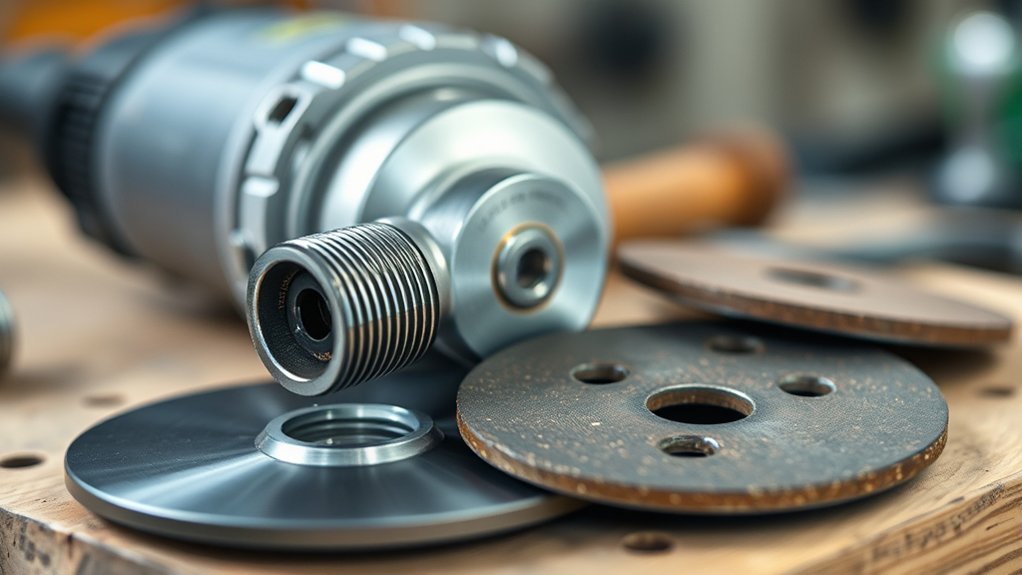
The arbor, also called the spindle, is the shaft at the center of an angle grinder. Its threads hold a threaded accessory or accept the clamp nut used with a flange-mounted wheel.
A 5/8-11 spindle has a nominal 5/8-inch thread diameter and 11 threads per inch. This is common on many U.S.-market angle grinders, but it is not universal. Other grinders may use M14, M10, or a tool-free system such as X-LOCK.
Why a 7/8-Inch Wheel Can Fit a 5/8-11 Spindle
A nonhubbed wheel does not normally center itself on the threaded part of a 5/8-11 spindle. It slides over the spindle and seats against the backing flange. A raised shoulder, often called the flange pilot, locating diameter, or hub circle, fits the wheel’s center hole and keeps it centered.
That is why a grinder can have a 5/8-11 spindle while its manual calls for an unthreaded wheel with a 7/8-inch hole. By contrast, a hubbed accessory marked 5/8-11 has internal threads and screws directly onto the matching spindle.
A 7/8-inch wheel hole can be correct on a 5/8-11 grinder because the backing flange—not the spindle threads—centers a compatible nonhubbed wheel.
Common Angle Grinder Mounting Systems
| Marking or System | What It Describes | How It Mounts |
|---|---|---|
| 5/8-11 spindle | Imperial spindle thread used on many U.S. grinders | Accepts matching threaded accessories or the specified backing flange and clamp nut |
| 5/8-11 hub | Internal threads built into an accessory | Threads directly onto a compatible 5/8-11 spindle |
| 7/8-inch hole | Unthreaded center bore found on many wheels and flap discs | Centers on the specified flange pilot and is secured by a clamp nut |
| M14 or M10 | Metric spindle thread | Requires accessories and mounting hardware designed for that exact metric thread |
| X-LOCK | Tool-free locking interface | Uses an X-LOCK-compatible accessory that clicks into the grinder’s mount |
Note: Do not choose a wheel from the center-hole measurement alone. Two accessories with similar-looking holes may require different flanges, guards, mounting directions, or grinder models.
Why Arbor Compatibility Matters for Safety
Correct mounting keeps the wheel centered, supported, and contained by the proper guard. An accessory that does not match the grinder’s mounting hardware can run out of balance, vibrate excessively, damage the flange, or contribute to loss of control.
OSHA’s portable-tool requirements state that grinding wheels must fit freely on the spindle and that controlled clearance is needed rather than a forced fit. OSHA also requires the spindle speed to be checked so it does not exceed the maximum operating speed marked on the wheel.
Safe Wheel Placement
A flange-mounted wheel should sit flat against a clean, undamaged backing flange and center fully on the flange pilot. It should not rest on damaged threads, debris, an improvised washer, or the edge of a misplaced flange.
A threaded accessory must match the grinder’s exact spindle thread. A 5/8-11 accessory must not be forced onto M14, M10, or damaged threads, even when it appears to start turning onto the spindle.
Proper Disc Selection
Before installing a disc, confirm all six compatibility points:
- Mounting system: Threaded hub, flange-mounted bore, M14, M10, X-LOCK, or another manufacturer-specified interface.
- Wheel diameter: It must not exceed the grinder’s rated capacity or the installed guard’s capacity.
- Wheel type and thickness: Use a wheel designed for cutting, grinding, finishing, wire brushing, or the specific task being performed.
- Maximum speed: The wheel’s RPM rating must equal or exceed the grinder’s maximum no-load speed.
- Flanges and nut: Use the correct size, shape, orientation, and condition for that wheel.
- Guard: Use the manufacturer-approved guard specified for the wheel and operation.
Warning: A wheel that physically fits is not automatically safe. Do not install circular-saw blades, oversized wheels, unapproved adapters, homemade spacers, or an accessory whose speed rating is below the grinder’s maximum RPM.
What Wheel Types Fit Your Angle Grinder?
The correct wheel depends on the grinder model, mounting system, guard, and intended operation. Some grinders are approved for both grinding and cutting, while others are not designed for cut-off work. Check the manual before using any of these accessories:
- Nonhubbed cut-off wheels: Thin wheels used for straight cuts in compatible materials. Many U.S. versions have a 7/8-inch hole and require the specified backing flange, clamp nut, and cutting guard.
- Depressed-center grinding wheels: Designed for material removal and edge or surface grinding. They require the correct grinding guard and flange arrangement.
- Threaded grinding wheels: Hubbed accessories that screw directly onto a matching spindle such as 5/8-11.
- Flap discs: Used for blending, deburring, and finishing. They are sold with threaded hubs, unthreaded bores, or X-LOCK mounts, so one mounting rule does not apply to every flap disc.
- Diamond blades: Used for compatible masonry, tile, stone, or concrete applications. Confirm the blade’s rotation arrow, guard, arbor system, diameter, speed rating, and dust-control requirements.
- Wire wheels and cup brushes: Often have threaded hubs. Their thread and speed rating must match the grinder, and the guard must not interfere as the wires expand during operation.
- X-LOCK accessories: Designed to click into an X-LOCK grinder. A standard threaded grinder does not become X-LOCK-compatible merely because the accessory’s center opening fits over the spindle.
Products Worth Considering

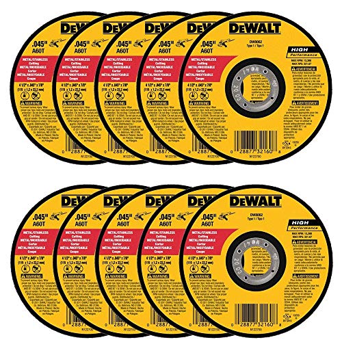
Thin . 045-Inch wheel design for fast burr free cutting this are easy to use

Premium and Value: This 10-pack 4-1/2 x 7/8-inch metal/stainless steel cut-off wheel set is specially formulated for fast cutting in metals and stainless steel
How to Read a Wheel Label
Look for the following information on the wheel, packaging, and grinder nameplate:
- Outside diameter, such as 4-1/2, 5, 6, or 7 inches
- Wheel thickness
- Wheel shape or type, such as Type 1/41 or Type 27/42
- Center-hole or hub specification, such as 7/8 inch or 5/8-11
- Maximum RPM
- Material and intended application
- Required direction of rotation, when marked
- Any required guard, flange, backing pad, or support hardware
How to Properly Install Wheels on Your Angle Grinder
Installation varies by model and accessory. The following process is a general safety checklist, not a replacement for the grinder and wheel manuals.
Warning: Switch the grinder off, unplug a corded model or remove the battery from a cordless model, and wait for every moving part to stop before touching the wheel, nut, flange, spindle, or guard.
Verify Arbor Size
- Read the grinder nameplate and manual to identify its spindle or mounting system.
- Confirm that the grinder is approved for the intended grinding, cutting, sanding, brushing, or masonry operation.
- Check the accessory’s mounting specification, diameter, thickness, wheel type, material application, and maximum RPM.
- Install the manufacturer-approved guard and side handle for the operation.
- Reject any wheel that is cracked, chipped, wet, warped, dropped, expired where an expiration date is provided, or otherwise damaged.
Engage the Flange Pilot or Hub Circle
Clean the spindle, backing flange, clamp nut, and wheel-contact surfaces. They should be flat and free of grit, burrs, rust flakes, and other debris.
For a nonhubbed wheel, seat the backing flange correctly on the spindle. Place the wheel flat against the flange and center its bore on the raised pilot. The wheel should sit evenly without being forced.
For a threaded accessory, verify that its internal thread exactly matches the spindle. Start it by hand to reduce the chance of cross-threading. Do not place an extra washer or flange behind a threaded accessory unless its instructions require one.
Secure Nut Positioning
Clamp-nut orientation depends on the grinder, wheel profile, and wheel thickness. Some nuts have a raised pilot on one face and a flatter face on the other. Follow the mounting diagram in the grinder manual rather than using a blanket rule such as “always flip the nut for a flap disc.”
- Thread the clamp nut onto the spindle by hand.
- Hold the spindle lock only after the spindle has stopped completely.
- Tighten the nut with the supplied wrench according to the manufacturer’s instructions.
- Use enough force to secure the wheel without distorting the flange or overtightening the assembly.
- Do not use an impact wrench, hammer, pipe extension, or other improvised leverage unless the manufacturer expressly permits it.
Check Clearance and Test the Installation
- Rotate the wheel carefully by hand and confirm that it does not touch the guard or another part of the grinder.
- Check that the guard is secure and positioned between the operator and the wheel.
- Reconnect power or reinstall the battery only after the setup is complete.
- Hold the grinder with both hands and keep yourself and bystanders away from the wheel’s plane of rotation.
- Start the grinder in a protected position and let it run without contacting the workpiece. Follow the manual’s test duration; many manufacturer instructions call for approximately one minute after installing an accessory.
- Stop immediately if the wheel wobbles, rubs, chatters, or produces an unusual sound.
Pro Tip: Photograph the flange and nut arrangement before removing a correctly mounted wheel. The photo can help you compare the replacement setup, but the current grinder manual remains the final authority.
Common Installation Mistakes to Avoid
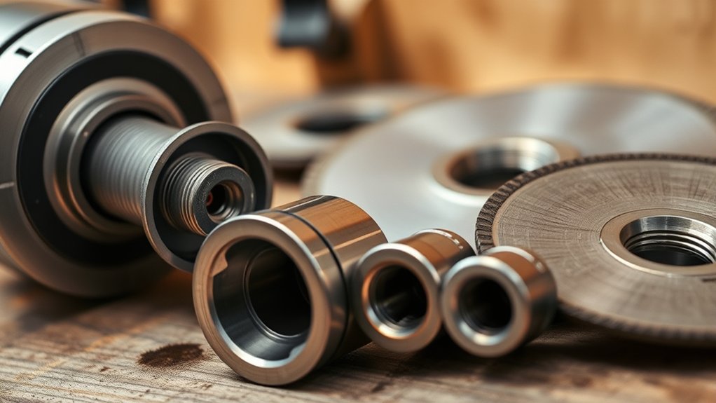
A common mistake is assuming that the wheel hole must equal the spindle’s threaded diameter. On many 5/8-11 grinders, an approved nonhubbed wheel has a 7/8-inch hole and is centered by the backing-flange pilot. The opposite mistake is assuming that every 7/8-inch wheel will fit every 5/8-11 grinder.
Avoid these additional errors:
- Forcing a tight wheel hole onto the spindle: A bonded abrasive wheel should not require force to slide into position.
- Adding an unapproved adapter or reducer: A loose generic bushing may interfere with the flanges or fail to center the wheel correctly.
- Installing the flange backward: The backing flange must seat on the spindle as shown in the manual.
- Using one nut orientation for every wheel: Follow the model-specific diagram and the wheel’s thickness or profile requirements.
- Using the wrong guard: A grinding guard may not provide the enclosure required for a thin cut-off wheel.
- Exceeding the grinder’s diameter capacity: Removing a guard to fit a larger wheel is not an acceptable solution.
- Ignoring the maximum RPM: A wheel rated below the grinder’s maximum speed may break apart.
- Side-loading a cut-off wheel: Thin cutting wheels are intended for straight cutting, not surface grinding or twisting in a cut.
- Checking the nut while the grinder is energized: Disconnect the tool and wait for a complete stop first.
Ensuring Proper Wheel Alignment
A correctly mounted wheel should sit flat, rotate without touching the guard, and show no visible side-to-side wobble. Do not try to correct poor alignment by running the wheel against scrap material.
- Confirm that the backing flange is seated fully on the spindle.
- Center a nonhubbed wheel on the flange pilot rather than on the threaded spindle alone.
- Check that the wheel and flanges are clean and undamaged.
- Confirm that the clamp nut is facing the direction shown in the manual.
- Rotate the wheel by hand before restoring power.
- During the no-load test, stand outside the wheel’s plane and stop immediately if vibration or noise appears.
Do not continue using a grinder that vibrates after a correctly mounted, undamaged wheel has been installed. The grinder may have a bent spindle, damaged bearing, worn flange, or another fault that requires qualified service.
Recommended PPE for Angle Grinder Work
Wheel compatibility does not replace personal protective equipment. OSHA identifies flying fragments, dust, noise, sparks, sharp material, and fire as hazards associated with portable power tools. Its portable and hand-held power-tool fact sheet recommends selecting PPE for the actual task.
- Safety glasses or goggles: Use impact-rated eye protection appropriate for the work.
- Face shield: Wear one over primary eye protection when sparks or fragments could strike the face.
- Hearing protection: Grinding and cutting can produce harmful noise levels.
- Respiratory protection or dust control: Use the collection method and respirator required for the material and work environment.
- Snug work gloves: Use task-appropriate gloves that preserve control and do not have loose material that could snag.
- Protective clothing: Wear long sleeves, long pants, and closed-toe work footwear. Avoid loose clothing, jewelry, and unsecured hair.
Keep the side handle installed when required and hold the grinder with both hands. Position the guard so it is between you and the wheel and directs fragments away from your body.
Warning: Grinding sparks can ignite fuel, solvents, sawdust, paper, dry vegetation, clothing, and hidden combustible material. Clear the spark path, protect nearby people and surfaces, and keep suitable fire-control equipment available.
Products Worth Considering
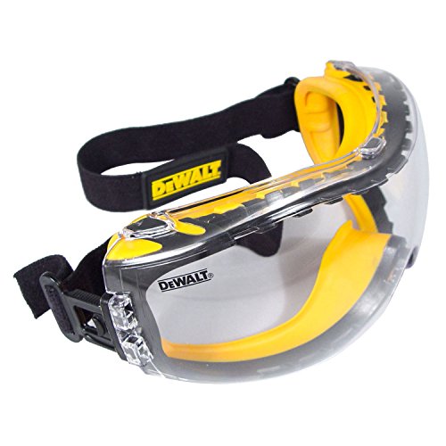
DEWALT ToughCoat hard coated lens provides tough protection against scratches.

WEAR IT ALL DAY: Soft rubber seal forms a gentle cushion around the eyes, providing a secure yet pressure-free fit for long hours in the lab or on-site projects; lightweight design reduces fatigue and keeps you focused on precision work.

COMPLETE PROTECTION — Pairing anti-fog and scratch-resistant goggles with a tough polycarbonate torch face shield, this unbeatable duo has you covered from splashes, dust, and debris. And they are built to resist high-speed impacts, even in extreme temperatures.
How to Maintain Your Angle Grinder and Wheels for Longevity
Regular maintenance supports reliable mounting and helps reveal damage before a wheel is installed.
- Disconnect the grinder before cleaning, servicing, adjusting, or changing an accessory.
- Clean the spindle threads, flange pilots, contact faces, and nut without removing metal or changing their shape.
- Inspect the guard for cracks, deformation, missing hardware, and a loose clamp.
- Replace worn, bent, cracked, or heavily scored flanges and nuts with the correct manufacturer-approved parts.
- Keep ventilation openings clear according to the grinder manual.
- Store wheels in a dry area where they will not be bent, dropped, exposed to chemicals, or damaged by moisture and temperature extremes.
- Keep wheel labels and packaging when they contain mounting, speed, date, or storage instructions.
- Check mounting tightness only after switching off the grinder, disconnecting power, and waiting for a complete stop.
The ANSI approval notice for B7.1-2017 identifies the standard as covering the safe use, care, and protection of abrasive wheels. Workplace users must also follow applicable regulations, employer procedures, and manufacturer instructions.
Safety Best Practices for Using Angle Grinders Effectively
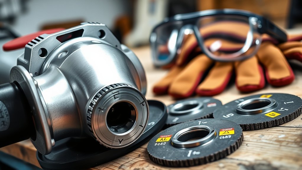
- Use only accessories specifically designed or recommended for the grinder and operation.
- Clamp or support the workpiece so it cannot move, pinch the wheel, or fall after a cut.
- Install the correct side handle and maintain a two-handed grip.
- Keep the power cord, clothing, and body away from the rotating accessory.
- Stand out of the wheel’s plane during startup and keep bystanders clear.
- Let the grinder reach operating speed before touching the workpiece.
- Apply controlled pressure and let the accessory do the work.
- Do not twist a thin cut-off wheel or use its side for grinding.
- Do not restart a cut-off wheel while it is pinched inside a cut. Stop the grinder, wait for it to stop, and correct the cause of binding.
- Lift the wheel from the work before switching off the grinder.
- Wait for the wheel to stop completely before setting the tool down.
- Direct sparks and debris away from people, glass, vehicles, hoses, cords, batteries, and combustible material.
Some materials create additional hazards. Cutting or grinding concrete, mortar, brick, stone, coatings, or treated metals may require dust extraction, ventilation, respiratory protection, or controls for hazardous fumes. Identify the material before beginning work.
Troubleshooting Common Angle Grinder Issues
| Symptom | Possible Cause | Safe Response |
|---|---|---|
| The wheel will not sit flat | Wrong flange, reversed flange, debris, incompatible bore, or damaged mounting surface | Disconnect the grinder, remove the wheel, clean and inspect every contact surface, and verify the manual’s mounting diagram. |
| The wheel remains loose after tightening | Incorrect nut orientation, wrong hardware, pilot bottoming out, or incompatible wheel thickness | Do not run the grinder. Confirm the wheel, flange, and nut combination specified for that model. |
| Strong vibration or wobble | Damaged wheel, off-center mounting, dirty flange, worn hardware, or grinder damage | Stop immediately, disconnect power, and replace or correct the faulty component. Have the grinder serviced if vibration continues. |
| The wheel rubs the guard | Wrong wheel diameter, incorrect guard, bent guard, or improper mounting | Do not remove the guard to create clearance. Install the correct wheel and approved guard. |
| The clamp nut is stuck | Overtightening, heat, debris, damaged threads, or wheel binding | Disconnect power and use the supplied spindle lock and wrench as directed. Do not apply heat or strike the wheel. |
| Unusual noise during the no-load test | Wheel damage, interference, loose hardware, bearing wear, or spindle damage | Switch off immediately and do not resume work until the cause is identified and corrected. |
Frequently Asked Questions
What size thread is an angle grinder arbor?
There is no single thread size for every angle grinder. Many U.S.-market models use a 5/8-11 UNC spindle, while other grinders use M14, M10, or a nonthreaded system such as X-LOCK. Check the grinder nameplate and manual before buying an accessory.
What does arbor size 5/8-11 mean?
The 5/8 refers to the spindle thread’s nominal diameter in inches, and 11 means there are 11 threads per inch. It describes an imperial thread, not the required center-hole diameter of every wheel used on that grinder.
Can I use a 7/8-inch arbor wheel on a 5/8-11 grinder?
Yes, when the grinder manual specifies a nonhubbed 7/8-inch wheel and the wheel is mounted with the correct backing flange, clamp nut, and guard. The flange pilot centers the wheel. This is different from a threaded 5/8-11 accessory, which screws directly onto the spindle.
Do I need an adapter for a 7/8-inch wheel on a 5/8-11 grinder?
Normally not when the grinder was designed to use that 7/8-inch nonhubbed wheel. Its original flange pilot acts as the locating surface. Do not add a reducer bushing, washer, or spacer unless both the grinder and accessory manufacturers approve that exact part and arrangement.
Which side of the angle grinder nut faces the wheel?
It depends on the clamp-nut design, wheel thickness, wheel shape, and grinder model. Some manuals place the raised pilot toward a thicker wheel and away from a thin wheel. Other mounting systems differ. Follow the diagram supplied with the grinder and accessory.
What else must match besides the arbor size?
The wheel diameter, thickness, shape, intended material, maximum RPM, flange arrangement, clamp nut, guard, and approved operation must all match the grinder. Arbor compatibility by itself does not make a wheel safe.
Conclusion
Understanding angle grinder arbor sizes starts with separating the spindle thread from the wheel’s mounting hole. A 5/8-11 spindle can accept a matching threaded accessory and, on many models, a nonhubbed 7/8-inch wheel centered by the specified backing flange. That does not make every 5/8-11 or 7/8-inch accessory interchangeable.
Before every job, verify the mounting system, wheel diameter, thickness, type, maximum RPM, flange, nut, and guard. Inspect the wheel and hardware, disconnect the grinder before adjustments, and stop immediately if the installed wheel does not sit flat or run smoothly. The instructions for the exact grinder and accessory always take priority over general advice.
Sources
- OSHA 29 CFR 1910.243 — Guarding of Portable Powered Tools — wheel inspection, free spindle fit, flanges, speed checks, and portable-grinder guards
- OSHA Safe Use of Portable and Hand-Held Power Tools — PPE, disconnection, wheel inspection, guarding, RPM, and startup precautions
- DEWALT DWE46101/DWE46102 Instruction Manual — 5/8-11 threaded accessories, 7/8-inch nonhubbed wheels, flanges, clamp-nut orientation, and guards
- Bosch GWS8-45 Instruction Manual — spindle-thread matching, flange locating diameters, speed ratings, PPE, and no-load testing
- Bosch Professional GWS 14-125 S Specifications — example of an M14 spindle and 22.23 mm wheel bore
- Makita X-LOCK System — current tool-free angle grinder mounting system and compatible accessories