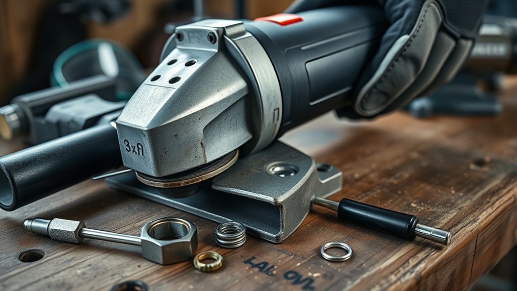
If your angle grinder guard won’t stay in place, stop using the grinder and disconnect power. Remove the wheel, identify whether the guard uses a detent pin, push-button lock, latch clamp, or screw clamp, then clean and refit it exactly as the model manual shows. A guard that still rotates without the release control, rocks on the collar, touches the wheel, or has cracked, bent, stripped, or worn parts must be replaced with the correct part or professionally serviced.
Last updated: July 22, 2026. Reviewed against current OSHA requirements and official DEWALT, Milwaukee, Bosch, and RYOBI instructions.
Quick Answer
Disconnect the grinder and remove the wheel. Clean and refit the correct guard by the model manual, then test it without touching the release control. If it rotates, lifts, rocks, rattles, or touches the wheel, do not run the grinder. Replace the damaged guard or locking part, or have the grinder serviced if the gearcase collar or built-in lock is worn.
Key Takeaways
- Do not operate an angle grinder with a guard that rotates freely, rattles, touches the wheel, or fails to lock.
- Guard designs differ, so use the grinder’s model and type number to find the correct manual and replacement parts.
- Clean away loose dust and grit, but do not file, grind, bend, shim, tape, or wire the guard into place.
- Use the guard approved for the grinder, wheel diameter, wheel type, and task.
- Replace damaged guard parts or have the grinder serviced if its mounting collar or locking mechanism is worn.
At a Glance
| Inspection Scope | Power-off identification, cleaning, refitting, and lock verification; repair time varies by model and part availability |
| Difficulty | Easy for cleaning and correct refitting; professional service recommended for damaged locking parts or mounting surfaces |
| Tools Needed | Official manual, soft brush, vacuum, lint-free cloth, and the manufacturer-specified driver, hex key, or supplied wrench |
| Stop Condition | Do not operate the grinder if the guard rotates without its release, rocks on the collar, touches the wheel, or shows damaged locking parts |
What Does Your Loose Angle Grinder Guard Symptom Mean?
Use the symptom below to choose the next safe action. This is a power-off check only. Remove the battery or unplug the grinder before touching the guard.
| Symptom | Likely Meaning | Safe Next Step |
|---|---|---|
| The guard moves only while you press its release | This may be normal for a push-button or detent design if it locks again at each approved position | Release the control and confirm the guard cannot rotate, lift, or rock |
| The guard rotates without pressing the release | The pin, detent, spring, lever, or alignment hole may be disengaged or worn | Remove and refit it by the manual; replace or service it if free rotation continues |
| The clamp closes but the guard rocks | Debris, the wrong collar size, low clamp tension, or a worn latch may prevent a secure fit | Clean the mating surfaces, confirm the exact guard, and adjust only the manual-identified screw |
| The guard touches the wheel | The guard may be bent or mismatched, or the wheel and flanges may be assembled incorrectly | Do not start the grinder; correct or replace the incompatible or damaged part |
| The guard loosens during a no-load check | Vibration may be exposing a worn lock, damaged collar, wheel wobble, or incorrect assembly | Switch off immediately, disconnect power, and inspect or service the complete assembly |
Identify Common Causes of Loose Grinder Guards
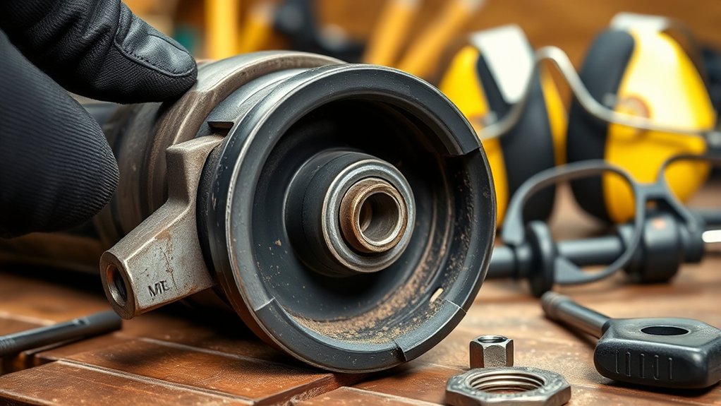
A loose guard creates a serious safety risk because it may no longer stay between you and the wheel. For U.S. workplaces covered by OSHA, 29 CFR 1910.243(c)(3) limits the exposed wheel angle on right-angle or vertical portable grinders to 180 degrees and requires the guard to be positioned between the operator and the wheel so broken-wheel fragments are directed away.
For a broader compliance overview, see OSHA guard requirements for portable grinders.
The exact cause depends on the grinder’s guard design. Common possibilities include:
- Incomplete engagement: The guard lugs, pin, tab, alignment hole, or detent did not fully engage during installation.
- Dirty mounting surfaces: Packed grinding dust, grit, paint, rust flakes, or metal chips keep the guard from seating on the gearcase collar.
- Incorrect guard: The guard is for another grinder model, wheel diameter, or accessory type.
- Weak clamp tension: A latch-style guard may have a loose adjustment screw, worn clamp, or damaged lever.
- Damaged locking parts: A broken spring, rounded detent, bent tab, worn locking pin, stripped screw, or cracked latch can prevent positive engagement.
- Damaged mounting collar: A burred, gouged, cracked, worn, or distorted gearcase collar may no longer hold the guard correctly.
- Missing model-specific hardware: Some grinders use a spring, screw, clip, ring, spacer, or other retaining part shown in the manufacturer’s parts diagram.
Warning: Do not operate a grinder with a guard that rotates freely, opens toward your body, rattles, contacts the wheel, or can be pulled off its mounting collar. Do not use tape, wire, homemade washers, or improvised shims to hold it in place.
OSHA rule: For covered workplace use of right-angle or vertical portable grinders, the guard must stay between the operator and the wheel, and the wheel exposure must not exceed 180 degrees.
Understand How Your Grinder Guard Locks
Before tightening or replacing anything, identify the guard mechanism. The grinder’s model number and type number are usually printed on its nameplate. Use both numbers when finding the official manual or parts diagram.
How Do Official Grinder Guard Locks Differ?
Manufacturer instructions show why a generic “tighten the guard” fix is unsafe. The release control, seating method, and permitted adjustment differ by model.
| Example | Locking Method | What Confirms a Secure Fit |
|---|---|---|
| DEWALT DCG407/DCG408 | Release lever, guard lugs, gearcase groove, and alignment holes | The release lever snaps into an alignment hole after the lugs seat in the gearcase groove |
| Milwaukee 2880/2881 | Guard lock lever with five detent slots | The guard seats on the tool and relocks in one of the specified detent positions |
| Bosch 1772-6 | Release/lock latch with a clamp-tension adjustment screw | The notches align with the spindle-neck keys, the latch closes, and the guard remains tightly seated |
| Selected RYOBI models | Aligned housing grooves with a push-button adjustment lock | The guard locks onto the housing before the button is pressed to change its position |
Detent or Locking-Pin Guards
Many tool-free guards slide onto lugs or tabs around the gearcase collar. A release lever retracts a locking pin so the guard can rotate. When released, the pin must enter an alignment hole or detent. For example, official DEWALT guard instructions require the release lever to snap into an alignment hole, while Milwaukee designs may use several detent slots.
Clamp-Latch Guards
Some guards wrap around the spindle neck and lock with a cam-style latch. Certain models include an adjustment screw that changes clamp tension. The screw should be adjusted only as described in the model’s manual. A latch that closes without clamping securely may be worn or damaged.
Screw-Clamp Guards
Older or application-specific guards may use a screw or bolt to clamp directly around the mounting collar. Use the specified driver and tightening method. Do not substitute a longer screw, add washers, or keep tightening a stripped fastener.
Clip-On Cutting-Guard Covers
Some grinders use an approved cover that clips over the grinding guard to create a more enclosed cutting guard. The cover must lock fully onto the exact base guard identified by the manufacturer. A generic cover that appears to fit is not proof of compatibility.
Note: Names such as Type 1, Type 27, Type A, Type B, cut-off guard, and clip-on guard vary across manufacturers. Follow the accessory chart in your grinder’s manual rather than choosing a guard by appearance alone.
Fixing a Slipping Grinder Guard: A Step-by-Step Guide
Use this process for inspection, cleaning, and correct refitting. Stop when you find cracked, bent, stripped, or badly worn parts.
- Disconnect all power: Unplug a corded grinder or remove the battery from a cordless grinder. Wait for the wheel and spindle to stop completely.
- Remove the wheel or accessory: Follow the manufacturer’s procedure and use the supplied wrench or specified tool. Never press the spindle lock while the wheel is moving.
- Confirm the model and guard: Compare the guard’s size, part number, locking design, and intended wheel type with the official manual or parts diagram.
- Identify the locking mechanism: Look for a release lever and detents, a clamp latch and adjustment screw, or a screw-clamp assembly. Do not assume that a spacer or washer is missing.
- Inspect the parts: Check the guard, lugs, tabs, detents, locking pin, spring, lever, latch, fasteners, and gearcase mounting collar for cracks, bends, stripped threads, severe wear, or impact damage.
- Clean the mounting area: Use a soft brush, vacuum, and lint-free cloth to remove loose dust and grit. Do not grind, file, sand, or reshape the guard or mounting collar.
- Refit the guard: Align its lugs, tabs, or notches with the matching slots or keys. Seat the guard fully before rotating or closing the locking mechanism.
- Adjust only as instructed: If the manual identifies a user-adjustable clamp screw, make small adjustments until the latch secures the guard. Do not force the lever or tighten a screw beyond the manufacturer’s procedure.
- Verify positive engagement: Release the locking control and try to rotate the guard by hand without pressing the release lever. A detent-style guard must remain engaged; a clamp-style guard must remain firmly seated.
- Install the correct wheel and guard: Match the wheel diameter, wheel type, rated speed, flanges, and guard to the grinder’s accessory chart.
- Perform the startup check: With the work area clear, position the guard between you and the wheel. Stand outside the wheel’s plane and follow the exact no-load test in your manual before contacting the workpiece. For example, the DEWALT DCG407/DCG408 manual specifies one minute at maximum no-load speed after an accessory is installed.
Pass/fail lock test: With power disconnected and the wheel removed, operate the release control, move the guard to an approved position, and let the control return. Then try to rotate, lift, and rock the guard without touching the release. Pass only if it stays seated and locked. Free rotation, lifting, or rocking is a fail.
If the grinder develops unexpected vibration, noise, wheel wobble, or guard movement during the startup check, switch it off immediately and disconnect the power. Inspect the wheel, flanges, spindle, guard, and mounting surfaces again. Do not continue using a wheel that creates abnormal vibration.
Match the Guard to the Wheel and Task
A guard can fit the grinder yet still be wrong for the installed wheel. Use the accessory chart in the manual to confirm all four of these details:
- Grinder model: Guards from similar-looking grinders may use different collars, tabs, detents, or clamping ranges.
- Wheel diameter: A 4-1/2-inch guard should not be assumed to protect a 5-inch wheel, and a larger guard may not lock correctly on a smaller grinder.
- Wheel type: Grinding wheels, abrasive cut-off wheels, diamond cutting wheels, flap discs, wire wheels, and cup wheels may require different guards.
- Application: A guard approved for surface grinding may not provide the enclosure required for cutting.
Some manufacturer manuals require a more enclosed guard arrangement for cutting. The DEWALT DCG407/DCG408 manual requires either a closed, two-sided cutting guard or a Type B guard with its approved clip-on guard for abrasive and diamond-coated cutting wheels. The Milwaukee 2880/2881 manual directs users to install the Type 1 clip-on guard when using a Type 1 wheel.
For the complete wheel-and-guard sequence, see how to install a cut-off wheel on an angle grinder. For wheel-mounting hardware, see the guide to angle grinder flanges and backing nuts.
Warning: Never use a thin cut-off wheel for side grinding. Side pressure can damage a wheel designed to cut only on its edge.
Key Safety Checks to Perform Before Using Your Grinder
Before every use, confirm that the guard is secure, correctly positioned, and compatible with the accessory. Also inspect the wheel, flanges, side handle, switch, cord or battery interface, and the grinder body.
Guard Stability Verification
- Confirm positive locking: The pin, tab, latch, detent, or screw must fully engage according to the manual.
- Check the guard position: Place the solid portion of the guard between your body and the wheel, with the opening directed away from you.
- Check for wheel clearance: Rotate the wheel by hand with the grinder disconnected. The wheel must not scrape or strike the guard.
- Check the mounting collar: The guard should sit squarely without rocking, lifting, or hanging on packed debris.
- Check the release control: The guard should rotate only when the designed release lever, button, or latch is operated.
If the guard moves without operating its release control, remove it and inspect the mechanism again. Do not try to compensate by adding an improvised washer or shim.
Proper Assembly Confirmation
Use the grinder’s official manual to match the guard, wheel, flanges, lock nut, and spindle. The wheel’s rated speed must meet or exceed the grinder’s marked maximum speed, and the wheel must fit the mounting hardware without being forced.
Check that the backing flange and locking flange or nut face the correct direction for the wheel thickness and design. Make sure the wheel is centered and does not project beyond the guard in a way the manual prohibits.
After installation, use the side handle and hold the grinder with both hands. Keep yourself and bystanders outside the plane of the wheel while it accelerates. OSHA’s shipyard fact sheet on portable and hand-held power tools advises disconnecting tools before service, inspecting them for damage, and using manufacturer-recommended accessories. Review the separate angle grinder PPE guide before grinding or cutting.
When to Replace a Grinder Guard Instead of Repairing It
Some guard problems do not have a safe user repair. Replace the correct removable part or arrange professional service when you find any of the following:
- Cracked, deeply gouged, heavily rusted, or bent guard metal
- Broken or rounded locking tabs, lugs, holes, or detents
- A locking pin that does not extend or stay engaged
- A broken spring, latch, lever, clip, or retaining component
- Stripped, seized, missing, or incorrect fasteners
- A clamp that remains loose after the manual’s permitted adjustment
- A guard that touches the correct wheel after proper installation
- A damaged, worn, cracked, or distorted gearcase mounting collar
- A guard that does not match the grinder model, wheel size, or application
- An unknown or altered guard with no verifiable compatibility information
Do not modify the guard to make it fit. Grinding, drilling, cutting, welding, bending, or enlarging its mounting points can weaken the guard or prevent it from containing fragments as designed.
Pro Tip: Photograph the grinder’s model and type label before ordering parts. Two grinders with the same marketing name may use different guards or locking components.
Products Worth Considering

Included: (1) DeWalt N441218 Angle Grinder Guard Replacement for Angle Grinder DCG414B

Genuine, OEM DeWalt Replacement Part
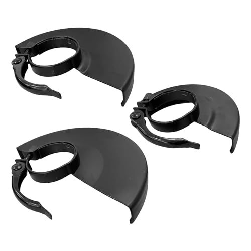
HIGH QUALITY MATERIAL: Angle grinder protective cover is made of iron material with good wear resistance and durability.
Troubleshooting Tips for Grinder Guards
Focus on the symptom rather than repeatedly tightening every visible screw. What appears to be a simple loose guard may come from the wrong guard, incomplete engagement, worn locking parts, or damage to the grinder itself.
The Guard Rotates Without Pressing the Release
A locking pin or detent may not be engaged, or the pin, spring, release lever, or alignment holes may be worn. Remove and refit the guard according to the manual. If it still rotates freely, replace the damaged part or use an authorized service center.
The Clamp Closes but the Guard Is Still Loose
Check for dirt beneath the clamp and confirm that the guard matches the mounting-collar diameter. If the manual shows an adjustment screw, adjust it in small steps. If the latch bottoms out, feels cracked, or requires excessive force, stop and replace the correct assembly.
The Guard Will Not Seat Fully
Look for misaligned tabs, a partially retracted locking pin, packed debris, the wrong guard, or damaged mounting surfaces. Do not hammer the guard into place. A correct guard should seat using the procedure shown in the manual.
The Guard Loosens After Startup
Stop immediately. Inspect the locking mechanism and check the wheel and flange assembly for wobble or abnormal vibration. A guard that stays secure by hand but moves when the tool runs may have worn locking parts or a damaged mounting collar.
The Guard Touches the Wheel
Do not run the grinder. Confirm the guard size, wheel diameter, wheel type, flange orientation, and wheel seating. Replace any bent guard, damaged flange, or incorrect component.
Preventive Maintenance for Angle Grinder Guards
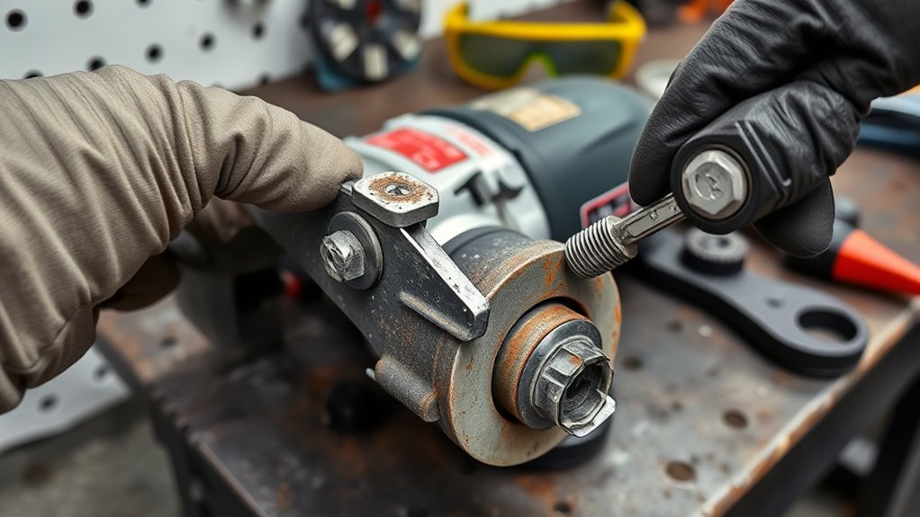
Inspect the guard before each use and after any drop, impact, jam, or wheel failure. Pay close attention to locking tabs, pins, alignment holes, springs, clamp levers, screws, and the mounting collar.
Remove the battery or unplug the grinder before cleaning. Use a brush and vacuum to remove loose abrasive dust from the guard and gearcase. Wipe the mating surfaces with a dry lint-free cloth. Avoid solvents unless the grinder manufacturer specifically approves them.
Check for missing hardware by comparing the assembly with the official parts diagram. If the design includes a spacer, spring, clip, or ring, replace it only with the correct part. Do not replace it with an ordinary washer that happens to fit.
Store the grinder where the guard will not be crushed or used as a support point. Do not carry or hang the grinder by the guard. Aftermarket parts should be used only when their manufacturer identifies the exact grinder models, wheel sizes, and applications they are designed to fit and the tool manufacturer permits their use.
Essential Tools and Equipment for Grinder Guard Repairs
Most safe inspections require only basic cleaning supplies and the tools identified in the grinder’s manual.
- Official instruction manual and parts diagram: Use these to identify the locking system, guard part number, fasteners, and permitted adjustments.
- Correct screwdriver, hex key, or supplied wrench: Match the fastener exactly to avoid stripping it.
- Soft brush and vacuum: Remove loose abrasive dust without reshaping the mounting surfaces.
- Lint-free cloth: Wipe the guard collar and mating surfaces after loose debris has been removed.
- Torque tool, when specified: Use a torque wrench or torque driver only if the manual provides a value and procedure for that fastener.
- Pliers, when specifically directed: Do not use pliers to bend tabs, stretch springs, pry the clamp, or reshape the guard.
Wear safety glasses while cleaning because trapped metal particles can become airborne. Gloves can protect against sharp burrs on a disconnected tool, but they do not make a damaged guard safe to reuse.
Products Worth Considering

Precise Compatibility: This grinder guard 43-54-1220 designed for esmeril, Compatible with Milwaukee grinders including 2780-20, 2781-20, 6117-30, 6117-31, and 6124-30. Ensure a perfect and secure fit for your tool


Precise Replacement:With replacement part number 397661 - 01, this guard is a direct and accurate substitute for your original equipment, ensuring seamless functionality. Any use of the brand name or model designation for this product is made solely to demonstrate compatibility.
Common Mistakes That Make Grinder Guards Slip
- Using a guard from a different grinder model because it appears to fit
- Using a grinding guard when the wheel requires an enclosed cutting guard
- Installing a wheel larger than the guard or grinder is designed to accept
- Failing to seat the guard lugs or locking pin fully before adjustment
- Leaving packed grinding dust on the mounting collar
- Tightening a screw that is not intended as a guard-tension adjustment
- Overtightening an adjustable clamp until the latch or guard distorts
- Continuing to run the grinder after the guard moves, rattles, or contacts the wheel
- Replacing a model-specific spacer, spring, clip, or ring with improvised hardware
- Filing, sanding, drilling, welding, or bending the guard or mounting collar
- Using tape, wire, cable ties, or adhesive to hold the guard in position
- Assuming the guard is responsible for a wheel that loosens on the spindle
A correct guard should lock using the parts and procedure supplied for that grinder. If it needs improvised hardware or unusual force, the fit is not safe.
Frequently Asked Questions
Why does my grinding wheel keep falling off?
The guard does not retain the wheel. A loose wheel can result from an incorrect or reversed flange, improper lock-nut installation, incompatible wheel hardware, damaged spindle threads, a wheel that is not seated correctly, or failure to tighten it by the manufacturer’s procedure. Disconnect the grinder and inspect the complete wheel-mounting assembly before using it again. The angle grinder flange and backing-nut guide explains the separate wheel-retention parts.
How should I position the guard on an angle grinder?
Position the solid portion of the guard between your body and the wheel so sparks and fragments are directed away from you. Engage the guard’s approved locking position and follow the operating-zone diagram in your grinder’s manual.
How close should a tongue guard be to a grinding wheel?
A tongue guard is associated with certain bench and floor grinders. OSHA’s bench-grinder rule limits the top opening to 1/4 inch in the covered situations. A handheld angle grinder uses a different guard system, so do not apply the tongue-guard measurement to it.
What are common angle grinder problems?
Common problems include abnormal vibration, wheel wobble, overheating, damaged cords or battery contacts, worn bearings, weak switches, damaged flanges, loose side handles, blocked vents, and guards that do not lock. Stop using the grinder when a defect affects control, wheel mounting, or guarding.
Can you use an angle grinder without the guard?
Do not use an angle grinder without the required guard for grinding or cutting. A manufacturer may identify a limited exception for a particular non-grinding accessory, such as some conventional sanding-disc setups, but that exception does not permit guardless grinding or cutting.
Should an angle grinder guard move at all?
An adjustable guard may rotate only while you operate its designed release button, lever, or latch. Once you release the control, it must lock in an approved position and remain seated. If it rotates, lifts, or rocks without the release control, disconnect the grinder and refit, replace, or service the locking system.
Can I tighten the guard’s adjustment screw?
Only tighten or loosen it when the official manual identifies it as a user-adjustable guard-clamp screw. Make small adjustments and confirm that the latch closes normally. Do not adjust unrelated gearcase screws or force a damaged clamp to hold.
Why does the guard rotate after it clicks into place?
The locking pin may not have entered the alignment hole or detent, or the pin, spring, lever, or guard collar may be worn. Remove and reinstall the guard. If it rotates without pressing the release control after correct installation, replace the damaged part or have the grinder serviced.
Can I use an aftermarket angle grinder guard?
Use one only when it is expressly identified for your exact grinder model, wheel diameter, wheel type, and application and its use is permitted by the grinder manufacturer. A similar collar diameter or bolt pattern does not prove that the guard is safe.
What should I do if the guard touches the wheel?
Do not start the grinder. Check the guard size, wheel diameter, wheel type, flange orientation, wheel seating, and guard condition. Replace bent or incorrect parts before operating the tool.
Safety Disclaimer: This article provides general information and does not replace the instructions for your grinder, guard, wheel, or workplace. Always disconnect power before inspection, use the required personal protective equipment, and take a damaged or uncertain guard assembly out of service until it is correctly repaired.
Conclusion
A secure angle grinder guard is a critical safety component, not an optional accessory. If the guard will not stay in place, disconnect the grinder, identify its exact locking system, clean the mating surfaces, and refit the correct guard by the manual. Continue only if it passes the power-off lock test and the model-specific no-load check. If it rotates without the release, rocks, touches the wheel, or shows damage, take the grinder out of service and replace the correct part or arrange professional repair.
Sources
- OSHA 29 CFR 1910.243: Guarding of Portable Powered Tools — portable abrasive-wheel guard requirements and right-angle grinder positioning
- OSHA: Safe Use of Portable and Hand-Held Power Tools — inspection, maintenance, guarding, accessory, and startup guidance
- DEWALT DCG407/DCG408 Instruction Manual — detent-style guard installation, alignment holes, cutting guards, and wheel mounting
- Milwaukee 2880-20/2881-20 Operator’s Manual — guard detents, wheel-size matching, clip-on cutting guard, and mounting inspection
- Bosch 1772-6 Operating and Safety Instructions — clamp-latch guard installation and adjustment-screw guidance
- RYOBI Support: How to Fit a Guard to a RYOBI Angle Grinder — groove alignment, push-button adjustment, and clip-on cutting-guard instructions for listed models
- OSHA 29 CFR 1910.215: Abrasive Wheel Machinery — bench- and floor-grinder tongue-guard measurement referenced in the FAQ