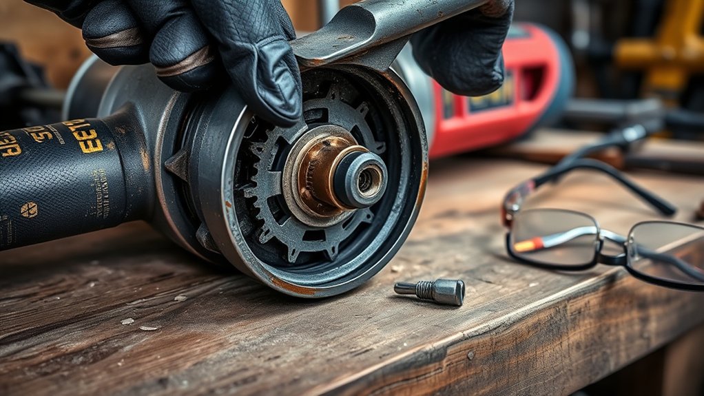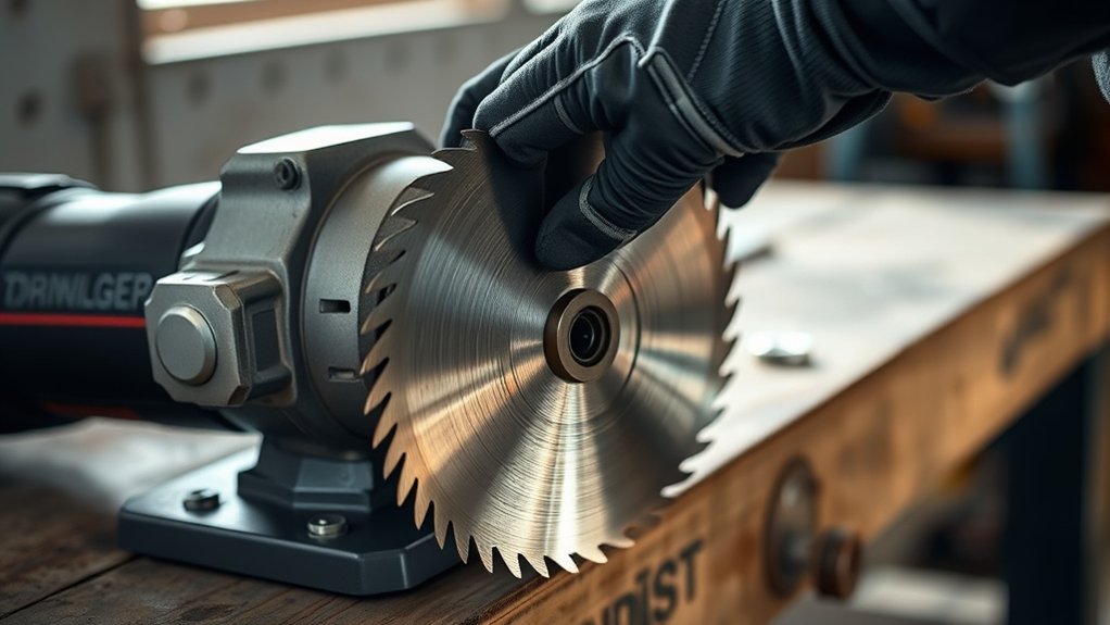
Installing a cut-off wheel on an angle grinder takes only a few minutes, but the wheel, mounting hardware, guard, and grinder must all be compatible. The exact flange and clamp-nut arrangement varies by model, so use the steps below for a conventional threaded-spindle grinder and let your tool manual override any general instruction.
Quick Answer
Disconnect the grinder, install the correct cutting guard, and confirm the wheel matches the grinder’s diameter, arbor, and RPM. Seat the wheel on the backing flange, orient the clamp nut exactly as your manual shows, tighten it with the supplied wrench, and perform a no-load test while standing outside the wheel’s rotation plane.
Key Takeaways
- The wheel’s diameter, arbor hole, thickness, maximum RPM, material rating, flange system, and required guard must match your grinder.
- A conventional grinder uses a backing flange and clamp or lock nut. The side handle helps you control the tool but does not secure the wheel.
- Clamp-nut orientation is model-specific. For many thin flat cut-off wheels, the nut’s flat face contacts the wheel, but your grinder manual is the final authority.
- Match any rotation arrow on a diamond wheel to the rotation arrow on the grinder.
- Never use a cut-off wheel for side grinding, and stop immediately if the mounted wheel wobbles, rubs, or vibrates.
At a Glance
| Time Required | About 5–10 minutes, plus the no-load test specified in your grinder manual |
| Difficulty | Beginner, provided you have the correct wheel, guard, flanges, and manual |
| Tools Needed | Compatible angle grinder, approved cut-off wheel, correct cutting guard, backing flange, clamp nut, supplied wrench, and side handle |
| Cost | No added cost if you already have a compatible wheel and guard; otherwise, the cost of the required replacement wheel or guard |
Warning: A damaged, under-rated, incorrectly clamped, or poorly guarded wheel can break at operating speed. Turn the grinder off and unplug it, or remove its battery, before touching the wheel, guard, spindle, flange, or clamp nut. Do not continue if any part is missing, damaged, or incompatible.
Check the Wheel, Grinder, and Guard Before Installation
Read the label on the wheel and the nameplate on the grinder before removing any hardware. A wheel that physically fits is not automatically safe to use.
Confirm the Wheel Is Compatible
- Wheel diameter: Do not install a wheel larger than the grinder’s rated capacity.
- Arbor hole: The wheel must center correctly on the grinder’s backing flange or approved adapter.
- Wheel thickness: The flanges and clamp nut must be designed to hold that thickness securely.
- Maximum speed: The RPM printed on the wheel must equal or exceed the grinder’s maximum no-load RPM. OSHA requires the machine speed not to exceed the wheel’s marked operating speed.
- Wheel application: Use a wheel approved for the material you plan to cut, such as steel, stainless steel, masonry, tile, or concrete.
- Guard type: Use the cutting guard specified by the grinder manufacturer for that exact wheel type.
OSHA’s portable abrasive-wheel requirements call for compatible wheel speed, proper inspection, clean contact surfaces, and an appropriate safety guard.
Note: These instructions cover a conventional grinder with a threaded spindle, backing flange, and clamp nut. An X-LOCK grinder uses a different snap-on mounting system and does not use conventional flange nuts. Follow the X-LOCK tool and wheel instructions instead.
Inspect the Wheel and Mounting Hardware
Do not install a wheel with cracks, chips, warping, water damage, a damaged arbor hole, a missing label, or an unreadable RPM rating. Check the backing flange and clamp nut for burrs, distortion, embedded debris, or worn threads.
Wipe the spindle and both flange contact surfaces clean. Dirt, rust flakes, or metal chips trapped behind the wheel can keep it from seating evenly.
Prepare Your Safety Equipment and Workspace
- Wear safety glasses with side protection. Add a face shield when flying fragments or heavy sparks are possible.
- Wear hearing protection and close-fitting work gloves.
- Use clothing that covers exposed skin and will not easily ignite from sparks.
- Use suitable dust collection and respiratory protection when the material or its coating creates a hazardous dust.
- Remove flammable liquids, sawdust, paper, fuel, and other combustible materials from the spark path.
- Keep bystanders outside the work area.
Step-by-Step Guide to Mounting the Cutting Disc on Your Angle Grinder
Products Worth Considering

[Diamond Technology] 1 equals 100, EZARC diamond 4 1/2 cut off wheel delivers 5,000+ more cuts for metal with much lower cost per cut compared to bonded cut-off wheels

4-1/2 Inch indestructible multi-material cut off disc for Angle Grinders, 7/8" arbor with 5/8" bushing, 3 Pack

Premium and Value: This 10-pack 4-1/2 x 7/8-inch metal/stainless steel cut-off wheel set is specially formulated for fast cutting in metals and stainless steel
1. Disconnect the Power
Switch the grinder off. Unplug a corded grinder or remove the battery from a cordless model. Wait until the spindle has completely stopped before pressing the spindle-lock button or touching the wheel.
2. Install and Position the Correct Guard
Install the guard approved for the selected cut-off wheel. Many conventional grinders require a closed, two-sided Type 1 cutting guard for a flat cut-off wheel rather than the more open guard supplied for ordinary grinding.
Lock the guard securely and position its closed section between you and the wheel. The guard should direct sparks and possible fragments away from your body without touching the wheel.
3. Install the Side Handle
Thread the side handle into the position that gives you the best two-handed control for the planned cut. Tighten it securely.
The side handle is sometimes mistakenly called a “side nut.” It does not clamp the wheel and should never be used to apply pressure to the mounting hardware.
4. Lock the Spindle and Remove the Clamp Nut
Press the spindle-lock button only while the grinder is off, disconnected from power, and fully stopped. Rotate the spindle by hand until the lock engages, then loosen the clamp or lock nut with the wrench supplied for your grinder.
Remove the clamp nut. Leave the backing or inner flange in place only if it is clean, undamaged, correctly oriented, and fully seated on the spindle flats. Reinstall it according to the manual if it came off with the old wheel.
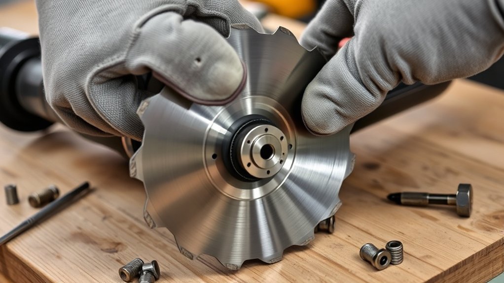
5. Seat the Cut-Off Wheel on the Backing Flange
Place the cut-off wheel over the spindle and center its arbor hole on the backing flange’s raised pilot. The wheel should lie flat against the flange without rocking.
Do not force a tight arbor hole onto the spindle, enlarge the hole, stack washers behind the wheel, or use an improvised adapter.
6. Check the Wheel’s Direction
If the wheel has a rotation arrow, match it to the rotation arrow on the grinder. This is especially important with directional diamond wheels.
If a bonded abrasive wheel has no arrow and its manufacturer describes it as non-directional, either labeled face may point outward. Keeping the label visible can make the wheel type and RPM rating easier to confirm later.
7. Install the Clamp Nut in the Correct Orientation
Thread the clamp nut onto the spindle by hand. For many thin, flat cut-off wheels on conventional grinders, the nut’s flat face contacts the wheel and its raised pilot faces away from the wheel. However, flange and nut designs vary, so follow the diagram in your grinder manual.
Do not copy the nut orientation used for a thick depressed-center grinding wheel unless the manual shows the same arrangement for your cut-off wheel. The wrong orientation can prevent a thin wheel from being clamped.
Pro Tip: Photograph the original flange and nut arrangement before removing the old wheel. The photo can help you compare the new setup, but the manual should remain your final reference.
8. Tighten the Clamp Nut
Press the spindle lock and tighten the clamp nut with the supplied wrench until the wheel is held securely. Use firm hand pressure, but do not add a pipe to the wrench or force the nut beyond the manufacturer’s instruction.
Overtightening can damage the wheel or distort the flanges. The nut should hold the wheel evenly without crushing it.
9. Inspect the Completed Assembly
Rotate the wheel slowly by hand while the grinder remains disconnected. Confirm that:
- The wheel remains centered and does not rock from side to side.
- The wheel does not touch the guard.
- The backing flange and clamp nut sit squarely.
- The guard cannot rotate out of position by hand.
- The side handle is tight.
- No loose tools or parts remain near the wheel.
10. Perform a No-Load Test
Clear the area and connect the grinder to power. Hold it with both hands and keep yourself and everyone nearby outside the plane of the rotating wheel.
Follow the startup test stated in your grinder manual. A common manufacturer instruction is to run a newly installed accessory at maximum no-load speed for one minute. Do not begin cutting during this test.
Switch the grinder off immediately if you notice wobbling, rubbing, pulsing, unusual vibration, cracking sounds, or movement at the clamp nut. Disconnect the power and inspect the wheel, flanges, nut orientation, guard, and spindle before trying again.
Secure the Cut-Off Wheel Without Overtightening
The clamp nut and backing flange must hold the wheel evenly across their contact surfaces. Tightening harder does not correct an incompatible arbor, damaged flange, reversed nut, or wheel that is not seated on the pilot.
If the wheel remains loose after the nut is snug, stop. Do not add homemade spacers, extra washers, tape, or a second nut. Confirm that you have the correct flange set and wheel thickness for the grinder.
Do not test security by bending or strongly tugging on a thin abrasive wheel. Instead, inspect the seating surfaces, rotate the wheel by hand, and watch it during the protected no-load test.
Products Worth Considering

Made To Withstand Even The Toughest Jobs


2-Piece Versatile Flange Nut Kit:This angle grinder flange nut set includes one 9mm silver D-ring nut for tight spaces and one 13.5mm black knurled nut for max stability. The ultimate 2-in-1 replacement parts kit for versatile grinding tasks.
Installing the Guard for Optimal Safety
Always use the guard required for the wheel and application. OSHA requires portable abrasive wheels to be used with appropriate guards, with the guard positioned between the operator and the wheel where applicable.
A guard does more than redirect ordinary sparks. It also helps reduce contact with the wheel and deflect fragments if a wheel breaks. Read the grinder manual before assuming that its standard grinding guard is approved for a flat cut-off wheel.
Depending on the grinder, the guard may attach with a latch, clamp lever, screw, keyed collar, or tool-free locking system. It should lock firmly and remain in position during use. Do not operate the grinder if the guard is cracked, bent, loose, modified, or rubbing the wheel.
The DEWALT DWE4100 and DWE4120 instruction manual, for example, requires matching flange hardware and a closed cutting-wheel guard for its documented Type 1 cutting-wheel setup. Your grinder may use different parts, so check its own manual.
What to Do Before Operating Your Angle Grinder
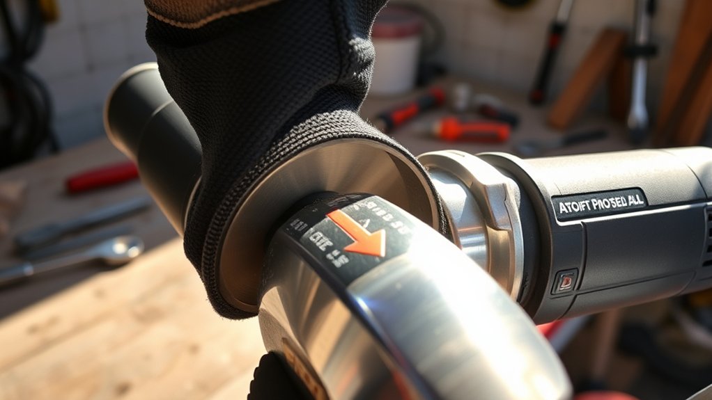
Run through this checklist before every use:
- Confirm that the wheel label matches the grinder, material, and planned cut.
- Verify that the wheel’s maximum RPM equals or exceeds the grinder’s maximum no-load RPM.
- Check that the wheel, backing flange, clamp nut, guard, side handle, cord, battery, and switch are undamaged.
- Confirm that the guard and wheel are securely installed and do not touch each other.
- Wear suitable eye, face, hearing, hand, clothing, and respiratory protection for the work.
- Remove flammable materials from the spark path.
- Clamp or support the workpiece so the cut does not close and pinch the wheel.
- Route the power cord away from the cutting path.
- Keep your body out of line with the wheel.
- Allow the wheel to reach full operating speed before contacting the workpiece.
Warning: A cut-off wheel is designed to cut with its outer edge. Do not use its side to grind, sand, or remove surface material. Side pressure can bend or overload the thin wheel and may cause it to break.
Prevent Binding and Kickback During the Cut
Support the workpiece on both sides of the cut when needed so the kerf stays open. Start the grinder outside the workpiece, allow it to reach full speed, and enter the cut gently.
Keep the wheel straight in the existing cut. Do not twist it, force it sideways, or change the cutting angle after the slot has formed. If the wheel binds, release the switch and hold the grinder still until the wheel stops completely. Remove it from the cut only after it has stopped.
Troubleshooting a Mounted Cut-Off Wheel
| Problem | Likely Cause | What to Do |
| Wheel remains loose after tightening | Clamp nut is reversed, wheel is too thin for the flange set, or the wrong hardware is installed | Disconnect power and compare the wheel and flange arrangement with the grinder manual |
| Wheel wobbles by hand | Debris behind the wheel, damaged flange, bent wheel, wrong arbor, or wheel not centered on the pilot | Remove the wheel, clean and inspect every contact surface, and replace damaged or incompatible parts |
| Wheel rubs the guard | Wrong guard, oversized wheel, bent guard, or incorrect flange arrangement | Do not run the grinder. Install the approved wheel, guard, and flange set |
| Strong vibration during the no-load test | Damaged or unbalanced wheel, improper seating, worn spindle, or damaged flange | Switch off immediately, disconnect power, and replace or correct the faulty component |
| Clamp nut will not loosen | Nut was overtightened, debris is in the threads, or the wheel bound during use | Use only the approved spindle lock and wrench method. Do not strike the spindle or apply heat |
Get to Know Your Angle Grinder’s Parts
Knowing the correct part names makes the instructions in your grinder manual easier to follow:
- Motor housing: Contains the motor and the main gripping area.
- Gear head: Transfers power from the motor to the spindle.
- Spindle: The rotating shaft that carries the wheel and mounting hardware.
- Spindle-lock button: Prevents spindle rotation while you remove or tighten approved mounting hardware. Use it only when the grinder is off and fully stopped.
- Backing or inner flange: Supports and centers the inside face of a non-hubbed wheel.
- Clamp or lock nut: Threads onto the spindle and holds the wheel against the backing flange.
- Wheel guard: Helps separate you from the wheel and redirects sparks and fragments.
- Side handle: Gives you two-handed control during startup and cutting. It does not tighten the wheel.
Some grinders use different hardware. A hubbed accessory may thread directly onto the spindle, while an X-LOCK grinder uses a tool-free wheel interface without a conventional backing flange or clamp nut.
Frequently Asked Questions
Which way does a cut-off wheel go on an angle grinder?
Match any rotation arrow on the wheel to the arrow on the grinder. Directional diamond wheels must follow the arrow. A bonded abrasive wheel without an arrow may be non-directional, but you should confirm that in the wheel instructions instead of assuming.
Which side of the clamp nut faces a thin cut-off wheel?
On many conventional grinders, the flat face of the clamp nut contacts a thin flat cut-off wheel and the raised pilot faces outward. This is not universal. Follow the flange diagram in your grinder manual because thicker wheels and different mounting systems may use another orientation.
How tight should the angle grinder clamp nut be?
Tighten it securely with the wrench supplied for the grinder, using the pressure specified in the manual. Do not use a pipe extension, impact tool, hammer, or excessive force. The nut must hold the wheel evenly without crushing it or distorting the flanges.
Can I use the normal grinding guard with a cut-off wheel?
Only when the grinder manufacturer approves that guard for the selected cutting wheel and application. Many flat Type 1 cut-off wheels require a closed, two-sided cutting guard rather than a standard open grinding guard.
Why does my cut-off wheel wobble after installation?
Possible causes include a bent wheel, debris behind the flange, an incorrect arbor size, a damaged flange, reversed mounting hardware, or failure to center the wheel on the flange pilot. Do not run the grinder until you identify and correct the cause.
Can I install a cut-off wheel without the backing flange?
Not on a conventional non-hubbed setup that requires one. Use the exact backing flange and clamp nut specified for the grinder and wheel. X-LOCK and certain hubbed accessories use different systems, so follow their dedicated instructions.
How do I change the cutting wheel on an angle grinder?
Disconnect the grinder, wait for the spindle to stop, engage the spindle lock, loosen the clamp nut, and remove the old wheel. Inspect and clean the flanges, install a compatible new wheel, orient the clamp nut according to the manual, tighten it, inspect the assembly, and complete the required no-load test.
Can I grind with the side of a cut-off wheel?
No. Thin cut-off wheels are designed to cut with their outer edge. Side loading can bend, bind, or break the wheel. Use an approved grinding wheel or flap disc when you need to grind a surface.
Sources
- OSHA 29 CFR 1910.243: Guarding of Portable Powered Tools — wheel inspection, RPM compatibility, flange contact surfaces, and guarding requirements
- OSHA: Safe Use of Portable and Hand-Held Power Tools — wheel mounting, operating-speed checks, startup position, PPE, and guard guidance
- DEWALT DWE4100, DWE4120, and DWE4120N Instruction Manual — cutting-wheel guard, flange arrangement, clamp-nut orientation, PPE, and no-load testing
- Makita GAG14 Instruction Manual — abrasive and diamond-wheel guard requirements and directional-arrow alignment
- Bosch GWX10-45PE X-LOCK Grinder Information — tool-free mounting systems that do not use conventional flange nuts
Conclusion
Installing a cut-off wheel safely is not just a matter of tightening a nut. You need the correct wheel, RPM rating, guard, flange set, clamp-nut orientation, and startup test for your grinder.
Disconnect the power before installation, follow the grinder manual whenever its instructions differ from general guidance, and stop if the wheel does not sit flat or run smoothly. Once the wheel is mounted correctly, use both hands, keep it straight in the cut, and never apply grinding pressure to its side.