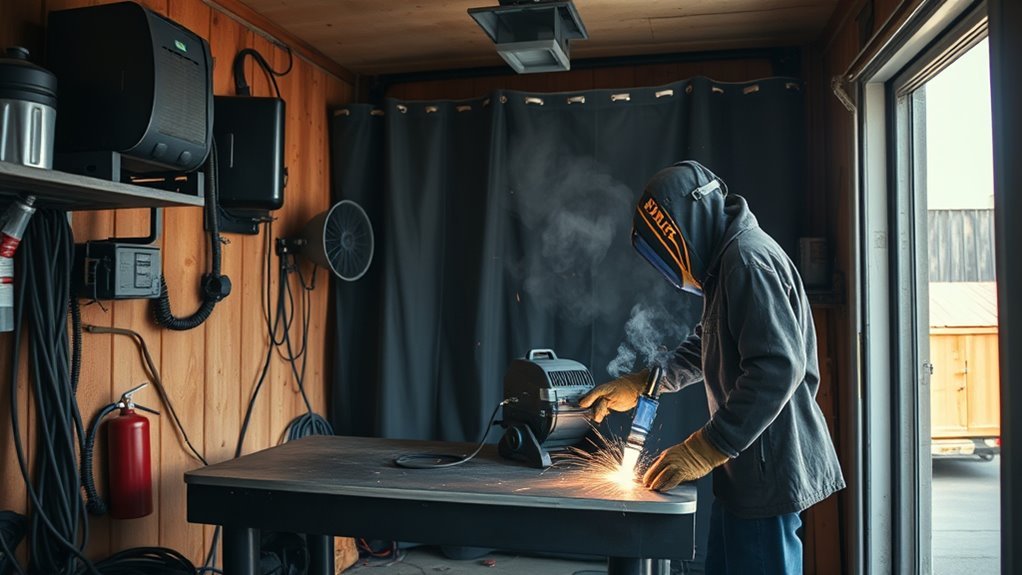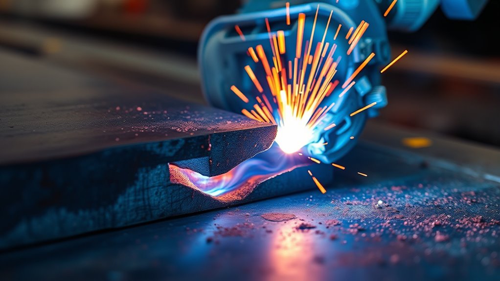
Burn-through in welding happens when the arc puts more heat into the joint than the base metal can support. The weld pool melts through the workpiece, leaving a hole, a collapsed root, or a dangerously thin area. It is most common on thin sheet, wide gaps, unsupported edges, aluminum, and repair metal already weakened by rust, grinding, or earlier welds.
Quick Answer
Burn-through occurs when welding heat melts completely through the base metal. Stop and let the area cool, then reduce heat input, improve fit-up, and use steady travel. Short stitches or suitable backing can help on thin non-critical sheet. Large, structural, pressure-containing, or safety-critical damage normally needs a patch, approved repair procedure, or qualified inspection.
Key Takeaways
- Burn-through is missing or severely thinned base metal caused by excessive heat for the material, joint, or gap.
- Check the actual metal thickness, fit-up, polarity, consumable, transfer mode, and machine chart before changing controls.
- MIG voltage and wire feed speed must stay balanced; lowering one control blindly can create an unstable arc or lack of fusion.
- Thin steel, aluminum, unsupported edges, wide root openings, and rust-thinned repair panels are especially vulnerable.
- Small non-critical holes may be rebuilt with cooled, low-heat tacks, while large or critical defects normally require removal and a fitted patch.
At a Glance
| Time Required | About 5 to 30 minutes to correct settings on matching scrap; roughly 15 to 90 minutes for a small non-critical sheet-metal repair |
| Difficulty | Beginner to intermediate on practice coupons or non-critical thin sheet; advanced or procedure-controlled for structural, pipe, pressure, and code work |
| Tools Needed | Welder, correct wire or filler, grinder or wire brush, clamps, welding PPE, matching scrap, and an optional suitable backing bar |
| Cost | Usually $0 to $30 for scrap, wire, filler, and abrasives; more when a patch panel, testing, or qualified inspection is required |
Warning: Do not treat burn-through on load-bearing structures, lifting equipment, pressure vessels, roll cages, frames, suspension or brake parts, fuel-adjacent components, or critical piping as a cosmetic repair. Never weld a used drum, tank, pipe, or closed container unless it has been cleaned, isolated, vented, and made safe under an approved procedure. Welding also creates fire, fume, UV, shock, and burn hazards, so use proper PPE, ventilation, and fire protection.
What Is Burn-Through in Welding?
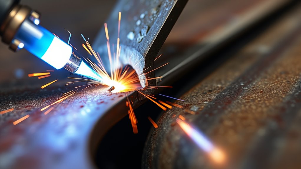
Burn-through occurs when excessive heat input melts completely through the base metal. It may leave a round hole, a melted edge, a collapsed or sagging root, or an area that looks closed from the front but is severely thinned on the back.
You see it most often when thin metal cannot carry the molten pool or move heat away from the weld zone fast enough. Instead of remaining supported at the joint, the pool opens, drops through, or pulls one edge away from the other.
Common triggers include excessive current, unsuitable voltage, slow travel, a long or poorly controlled arc, too much time in one spot, repeated welds without cooling, poor joint fit-up, and a root opening that is too wide for the process and filler size.
In practical terms, burn-through means the workpiece could not absorb the energy delivered per unit length without losing thickness. Higher current or voltage can raise arc power, while slower travel leaves that energy concentrated over a shorter length of joint. Research on fully penetrated GTAW pools also shows that travel speed changes pool size and behavior.
You prevent burn-through by matching the process and settings to the actual remaining metal thickness, keeping the joint clean and supported, and maintaining controlled travel. For MIG work, using a smaller compatible wire diameter can improve control on thin metal, but wire feed speed and voltage still need to remain balanced.
Burn-Through vs Other Weld Defects
Burn-through is easy to confuse with excessive penetration, undercut, porosity, or lack of fusion. The correct fix depends on identifying the actual defect rather than treating every hole or sunken bead as the same problem.
| Defect | What You See | Main Cause |
| Burn-through | Hole, missing base metal, melted edge, or collapsed root | Too much heat for the thickness, joint, support, or gap |
| Excessive penetration | Heavy root reinforcement or a bead protruding far through the back | High heat or a large root opening, but the joint has not necessarily opened into a hole |
| Undercut | A groove melted beside the weld toe | Excessive heat, poor angle, unsuitable arc length, or incorrect bead placement |
| Porosity | Small rounded pinholes or internal cavities | Gas trapped by contamination, moisture, coatings, or shielding problems |
| Lack of fusion | Weld metal sits on the surface or fails to tie into one edge or the root | Heat too low, travel too fast, poor angle, contamination, or poor joint access |
Porosity can appear in the same bad weld, but it is not the same problem as burn-through. If you are troubleshooting gas pockets, see this guide on porosity in welding. If the base metal is missing or an edge has melted away, focus first on heat control, fit-up, and support.
Note: Do not lower the settings so far that the weld only covers the hole without fusing to sound metal. The corrected test weld must still tie into both edges and achieve the penetration required for the joint.
How Burn-Through Damages Weld Strength
When excessive heat punches through the joint, it removes metal that should be carrying load. The weld and base metal lose effective cross-section, so the joint may no longer support the force, pressure, vibration, or fatigue loading it was designed to handle.
A burn-through hole is not merely a surface mark. It is missing metal, reduced thickness, and a possible stress concentration in the joint.
The missing or thinned area can concentrate stress at its edges. Under vibration, bending, pressure, or repeated loading, that area may become the starting point for a crack, leak, or further tearing.
Burn-through can also distort the heat-affected zone. Severe local heating may pull thin edges out of alignment, enlarge the joint gap, or make the next tack even harder to control. Repeated attempts to fill the same unstable edge can spread the damaged area.
For structural welds, pressure parts, frames, safety brackets, lifting points, and code-governed work, a visible burn-through defect may require removal, an approved repair, documentation, testing, or rejection under the applicable welding procedure and inspection criteria. Do not assume that closing the visible hole restores the original strength.
What to Check Before Changing the Welder Settings
Do not begin by turning one control down at random. First identify why the joint cannot support the weld pool.
- Measure the actual metal thickness. Check the thinnest remaining edge, not only the nominal thickness of the new sheet.
- Identify the material. Confirm whether it is carbon steel, stainless steel, aluminum, galvanized steel, cast material, or an unknown alloy.
- Inspect for thinning. Rust, corrosion, grinding, previous weld removal, and stretched body panels can leave much less metal than expected.
- Check the joint. Measure the root opening and look for unsupported edges, uneven cuts, poor overlap, or an outside corner that concentrates heat.
- Confirm the process and consumable. Check wire or electrode diameter, classification, shielding gas, transfer mode, and the manufacturer’s recommended thickness range.
- Verify polarity. MIG, gas-shielded flux-core, self-shielded flux-core, TIG, and stick consumables may require different polarity. Follow the machine and consumable instructions.
- Start from the machine chart. Use the door chart, manual, or approved welding procedure as the baseline rather than copying a setting from a different welder.
- Test on matching scrap. Use the same alloy, thickness, joint style, position, backing condition, and gap whenever possible.
What Causes Burn-Through in Welding?
Most burn-through starts with too much energy in too small an area. That condition may come from machine settings, slow movement, a wide gap, thin base metal, unsuitable polarity, an overly large consumable, poor joint support, or several of these problems at once.
| Cause | Why It Burns Through | Best Correction |
| Current or wire feed speed too high | Melts the base metal faster than the joint can support the puddle | Reduce the relevant control in small steps while keeping voltage and arc behavior properly balanced |
| Voltage or arc length unsuitable | Can create an overly wide, fluid, or difficult-to-control puddle | Return to the recommended range and make small coordinated adjustments for the process |
| Slow travel or excessive dwell | Leaves the arc over one area long enough for heat to accumulate | Use steady travel, a small stringer bead, or spaced stitch welds while maintaining fusion |
| Large root gap or poor fit-up | Leaves the molten pool unsupported and exposes thin edges directly to the arc | Refit and clamp the joint, add correctly spaced tacks, or install a fitted filler strip or patch |
| Thin, rusty, or ground-down metal | Has too little sound cross-section to absorb heat or anchor the repair | Cut back to solid metal rather than stacking weld onto a disappearing edge |
| Wrong polarity or unsuitable consumable | Changes arc behavior, penetration, deposition, and heat distribution | Check the wire, rod, machine, and process instructions before continuing |
| Heat buildup from repeated tacks | Each tack starts on metal that is already hot and weaker | Skip around the joint and allow adequate natural cooling between deposits |
Good joint preparation matters as much as the machine settings. Large gaps, uneven edges, rust, paint, oil, plating, and loose clamps make the puddle harder to control. If the joint is dirty or unsupported, one edge may melt before filler can bridge the opening.
How Joint Design Affects Burn-Through
Thin edges and open joints concentrate heat. A butt joint with a wide gap gives the pool little support, while an outside corner places the arc directly on two exposed edges. A close-fitting lap joint is often more tolerant because the overlapping metal provides more mass and support.
- Butt joint: Keep the gap uniform and within the range recommended for the process. Use frequent alignment tacks before filling the joint.
- Lap joint: Clamp the sheets tightly so the upper edge does not lift away and create an unsupported opening.
- Outside corner: Aim carefully and avoid dwelling on either exposed edge. This joint can open quickly on thin sheet.
- Edge weld: Use the lowest stable, properly balanced setting because the edge has little surrounding metal to carry heat away.
- Open root: Follow the qualified root opening, land, consumable, and procedure. Do not improvise a code root by simply lowering the machine.
Visual Signs of Burn-Through While Welding
You can often catch burn-through before a large hole opens. Watch the leading edge of the puddle and stop as soon as the joint begins to lose shape.
- The puddle suddenly drops, widens, or becomes much more fluid.
- One edge pulls away or melts faster than the filler can join it.
- The back side develops a bright glowing spot, heavy sag, or dripping metal.
- The arc sound changes because the gap has opened.
- The bead becomes flat, sunken, or cratered instead of maintaining a controlled profile.
- A tack that worked on cold metal suddenly opens a hole after several nearby tacks.
Pro Tip: Run a short test on scrap with the same alloy, thickness, joint gap, welding position, and backing condition. Examine the front and back. If the coupon sags, melts at one edge, or lacks fusion after cooling, correct the setup before touching the finished part.
Which Welding Processes Are Most Prone to Burn-Through?
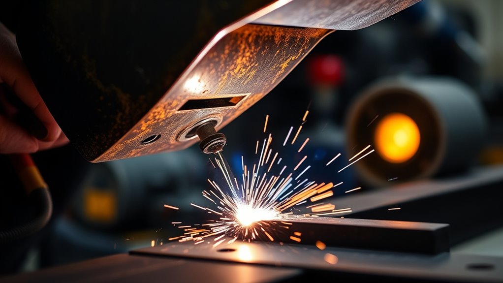
Any fusion-welding process can cause burn-through when its heat, consumable, technique, or joint design is unsuitable for the material. The process name alone does not determine the risk. The usable operating range, transfer mode, polarity, travel speed, and operator control matter more.
MIG Welding
MIG welding can burn through thin sheet when voltage, wire feed speed, or travel speed are not balanced. In constant-voltage MIG welding, changing wire feed speed changes welding current, while voltage influences arc length and bead shape. Make small coordinated changes rather than reducing one control until the arc becomes unstable.
Use the machine chart as a starting point. Short-circuit transfer is commonly used on thin carbon steel, while suitable pulsed programs can reduce average heat input and improve control on some steel, stainless, and aluminum applications. A smaller compatible wire, such as 0.023- or 0.024-inch solid wire, may improve control on thin steel when the welder supports it.
Keep the arc on the leading edge of the pool and use short stitches or separated tacks instead of one long pass when distortion and burn-through are likely.
TIG Welding
TIG welding provides precise control, but its concentrated arc can open thin metal quickly if the torch pauses in one spot. Use a short, stable arc, the lowest current that still provides sound fusion, and a foot pedal, fingertip control, or suitable pulse function when available.
Add filler before an edge collapses, move steadily, and avoid repeatedly reheating the same small area. Keep the tungsten close enough for control without touching the puddle or contaminating the electrode.
Stick Welding
Stick welding is difficult on very thin sheet because the electrode must operate above a minimum stable current. A large rod, long arc, or slow travel can overwhelm the joint.
Use the smallest suitable electrode, the correct polarity, a tight controlled arc, and the lowest stable amperage permitted by the electrode manufacturer. For automotive body-gauge sheet, MIG or TIG is usually easier to control than a conventional stick setup.
Flux-Cored Welding
Flux-cored welding must be treated according to the exact wire. Gas-shielded and self-shielded wires may require different polarity, stickout, voltage, and technique. Many self-shielded wires run on DCEN, but that is not universal, so verify the wire label or data sheet.
Some flux-cored consumables are not intended for very thin panels. Use the smallest suitable diameter, confirm the recommended thickness range, and review these flux-core welding tips before practicing on matching scrap.
What Should You Adjust First?
| Process | Check First | Then Correct |
| MIG/GMAW | Wire diameter, polarity, shielding gas, transfer mode, voltage and wire-feed balance | Reduce heat in small coordinated steps, keep steady travel, and use shorter deposits |
| TIG/GTAW | Peak current, pedal or remote control, arc length, filler timing, and joint gap | Lower peak current, shorten dwell time, add filler earlier, or use suitable pulse control |
| Stick/SMAW | Electrode diameter, classification, polarity, current range, and arc length | Use a smaller suitable rod, lowest stable current, tight arc, and controlled travel |
| Flux-core/FCAW | Exact wire data sheet, polarity, stickout, voltage range, and minimum recommended thickness | Correct the setup first; then reduce settings or change to a more suitable process if necessary |
Burn-Through on Steel, Stainless, Aluminum, and Coated Metal
Mild Steel
Clean mild-steel sheet is generally forgiving, but body panels, mower decks, exhaust parts, and older repairs may be thinner than they appear. Use close fit-up, a small compatible wire or filler, spaced tacks, and minimal grinding. Replace metal that has become paper-thin from corrosion.
Stainless Steel
Use the correct stainless filler and shielding setup, keep the joint clean, and limit heat buildup and distortion. Do not use a carbon-steel brush or contaminated abrasive on stainless. When a qualified procedure sets interpass-temperature or heat-input limits, follow those values rather than relying on appearance alone.
Aluminum
Thin aluminum can move from poor fusion to burn-through within a narrow operating window. The oxide layer must be removed with suitable dedicated tools, and the joint must be clean. Aluminum MIG welding often requires faster travel than steel to prevent heat buildup. Suitable pulse controls can improve heat management, but the wire, gas, filler alloy, and machine program must match the base material.
Galvanized, Painted, or Coated Metal
Do not weld through unknown paint, plating, undercoating, solvent residue, or preservative coatings. Heating these materials can create hazardous fumes, contaminate the puddle, and hide weak metal. Remove coatings far enough from the heated area under the applicable safety procedure and use effective ventilation or respiratory protection when required.
Rust-Thinned or Previously Repaired Metal
If the arc keeps chasing the edge away, the problem may be missing base metal rather than a setting that is slightly too hot. Stop adding weld, remove the weakened section, and make a patch that reaches sound material. Welding onto rust scale, pinholed sheet, or a feather-thin ground edge rarely creates a durable repair.
How to Prevent Burn-Through in Welding
To prevent burn-through, control heat, support, and fit-up before the arc starts. Match the process, current, voltage, wire feed, filler size, polarity, transfer mode, and travel speed to the material and joint.
- Clean the joint. Remove rust, oil, paint, plating, moisture, and other contamination using methods appropriate for the material.
- Confirm sound metal. Measure or inspect the remaining thickness and cut away metal that is too thin to support a repair.
- Improve fit-up. Close excessive gaps, align the edges, clamp both pieces firmly, and tack the joint before filling it.
- Start with approved settings. Use the machine chart, consumable data sheet, or qualified welding procedure.
- Reduce heat in small steps. Adjust the controls that apply to the process while preserving a stable arc and adequate fusion.
- Keep the arc controlled. Use the recommended arc length or voltage range rather than allowing a broad, wandering arc.
- Move steadily. Do not linger over a thin edge. Use short stringer beads, stitches, or separated tacks when appropriate.
- Use a suitable smaller consumable. A smaller wire, filler rod, tungsten, or stick electrode can improve control when the machine and procedure support it.
- Support the back side when appropriate. A clean copper backing bar or spoon can support and cool suitable carbon- or stainless-steel sheet repairs.
- Control accumulated heat. Skip around the joint and allow natural cooling between stitches rather than stacking welds in one hot area.
- Inspect the test weld. Check both sides for sag, holes, undercut, poor tie-in, or inadequate penetration before welding the final part.
For thin flux-core work, proper machine settings are especially important because polarity, voltage, wire feed, stickout, and travel technique depend on the exact wire.
Note: A backing bar can help control a puddle, but it does not make an unsuitable joint acceptable. Confirm that the backing material and technique are permitted for the alloy, process, and welding procedure.
Products Worth Considering
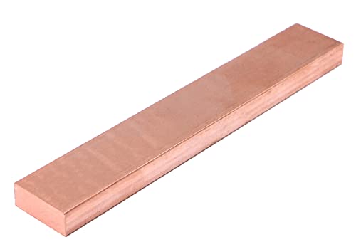
Material:Copper Flat BAR

Dual Safety Assurance Structure:Features stainless steel dual-bolt fastening, enhancing structural stability during high-temperature welding operations.

Size: 2Pcs copper bar 1/8"(3mm) x 1"(25mm) x 12"(305mm) Dimensions are hand-cut, so slight variations are normal. The tolerance is +0.5 to 1 mm.
How to Fix Burn-Through in Welding
Fixing burn-through depends on the hole size, the condition of the surrounding metal, access to the back side, and the part’s function. A pinhole in sound non-critical sheet may be repaired with short tacks. A large opening, a repeatedly melting edge, or a critical joint normally needs a cut-out, fitted patch, and qualified inspection.
Products Worth Considering
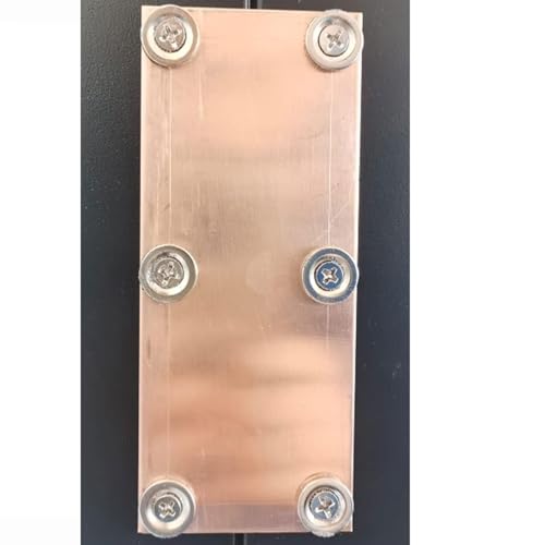
Boost your welding efficiency with the Magnetic Backing Copper Welding Spoon! Designed for butt-welding sheet metal panels, this essential tool ensures seamless welds without damaging the material. With its detachable magnet design, you can easily replace the magnet to continue welding, saving you money in the long run.
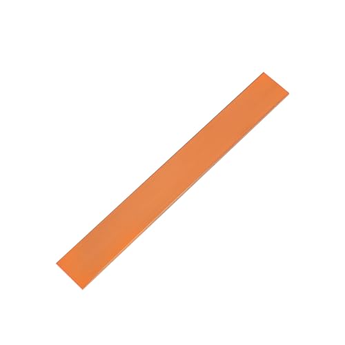
Size: Each package includes 1 PCS of 1/8"(3mm) x 1"(25mm) x 8"(204mm) copper flat bar, providing ample material to meet a variety of needs. It serves as a cost-effective solution for projects requiring a stable supply of copper or for users who need to replace worn parts.

Size: 1Pcs copper bar 1/8"(3mm) x 1"(25mm) x 6"(152mm) Dimensions are hand-cut, so slight variations are normal. The tolerance is +0.5 to 1 mm.
Small Hole Repair
- Stop welding immediately. Continuing to feed heat into the opening will enlarge it.
- Let the area cool naturally. Do not quench the weld unless the applicable procedure specifically permits it.
- Clean the damage. Remove slag, soot, oxide, coatings, sharp edges, and contaminated weld metal.
- Inspect the surrounding thickness. If the edge is cracked, deeply undercut, corroded, or paper-thin, cut back to sound material instead of filling over it.
- Add suitable backing if permitted. For appropriate non-critical steel sheet, clamp clean copper tightly behind the hole to support the puddle and draw away heat.
- Reset and test the welder. Use matching scrap to confirm that the revised settings still provide fusion without opening another hole.
- Place one quick tack at the edge. Let it solidify and cool before placing the next tack on the opposite side.
- Work around the opening. Alternate sides so no single edge receives all the heat. Gradually shrink the opening with small deposits.
- Close the center last. Do not hold the arc over the unsupported middle and attempt to fill the hole in one pass.
- Dress the repair lightly. Grind only enough to achieve the required profile. Heavy grinding can thin the repair again.
- Inspect both sides. Look for cracks, remaining pinholes, undercut, sharp notches, incomplete fusion, excessive penetration, or new thinning.
Large Hole or Thin Surrounding Metal
If the hole is large, the edge keeps melting away, or the metal around it is weak, cut out the damaged section and weld in a fitted patch. For automotive body panels, that generally means trimming to clean metal, making a patch with a close uniform gap, placing alignment tacks around the perimeter, cooling between tacks, and finishing with restrained grinding.
Do not keep adding weld to a growing hole. That adds heat, increases distortion, traps contamination, and often turns a small repair into a much larger one.
When You Should Not Fill the Hole Yourself
Stop and obtain the applicable repair procedure or a qualified welder or inspector when the defect involves:
- A frame, roll cage, lifting point, suspension mount, steering part, or brake component
- A pressure vessel, boiler, hydraulic component, process pipe, or critical pipeline
- A fuel tank, fuel line, used drum, closed container, or unknown hollow section
- A certified structural weld or a joint governed by a welding code or contract specification
- Cracked, heat-damaged, hardened, cast, or unidentified material
- Damage that extends well beyond the visible hole
- A repair that cannot be inspected from the back or tested as required
Burn-Through Troubleshooting Guide
| Problem | Likely Cause | Correction |
| Hole opens as soon as the arc starts | Settings too hot, consumable too large, or metal much thinner than expected | Stop, measure the metal, verify the chart and polarity, use a suitable smaller consumable, and test on scrap |
| Edges melt before they join | Gap too large, exposed outside corner, poor aim, or travel too slow | Improve fit-up, add alignment tacks, redirect the arc, use backing, or install a patch |
| Bead is wide, flat, and sunken | Excessive heat, unsuitable voltage, slow travel, or too much dwell | Return to the recommended process window and make small balanced corrections |
| Repair hole keeps growing | Trying to fill too much at once or welding onto unsound edges | Cool the area, use alternating quick tacks, add permitted backing, or cut out and patch the section |
| First tacks work, but later tacks burn through | Accumulated heat | Skip farther around the joint and allow more cooling time |
| Only the old metal melts away | Corrosion, grinding, or earlier repairs left the old edge thinner than the patch | Trim farther back until both sides of the joint are sound |
| Flux-core arc is harsh or uncontrollable | Wrong polarity, stickout, voltage, or unsuitable wire | Stop and follow the exact wire manufacturer’s setup instructions |
| Pinholes appear after grinding | Incomplete closure, porosity, or excessive grinding | Clean and inspect the repair, correct contamination or shielding problems, and rebuild only on sound metal |
How to Inspect a Burn-Through Repair
A smooth front surface does not prove that a repair is sound. Inspect the back whenever access permits and use any testing required by the procedure or part.
- Confirm that the hole is fully closed and no light is visible through pinholes.
- Look for cracks at the edge of the original hole and at tack starts and stops.
- Check both weld toes for fusion and sharp undercut.
- Check the back for excessive sag, incomplete fusion, contamination, or a second thinned area.
- Make sure grinding has not removed most of the repair thickness.
- Check panel alignment and distortion before coating or assembly.
- Leak-test sealed non-critical work using a method suitable for the component.
- Obtain the required visual, penetrant, magnetic-particle, radiographic, ultrasonic, pressure, or destructive test for regulated work.
Safety and Inspection Notes
Welding is hot work. The OSHA welding, cutting, and brazing requirements address fire-safe work areas, combustibles, extinguishing equipment, fire watches, used containers, ventilation, and other precautions. Move combustible material away or protect it from sparks and heat. Keep suitable extinguishing equipment ready, and continue any required fire watch after welding.
Never weld, cut, or heat a used fuel tank, drum, pipe, or container merely because it appears empty. Residue and trapped vapor can ignite or explode. Closed cavities also need proper venting because heated air or gas can build pressure.
Welding fumes also matter. OSHA’s guidance on welding fumes and gases recommends understanding the materials being welded, removing coatings that may create toxic exposure, keeping the plume away from the breathing zone, and using suitable general or local exhaust ventilation. Outdoor welding does not automatically guarantee adequate ventilation.
Use the correct welding helmet shade, safety glasses, gloves, hearing protection, flame-resistant clothing, and electrical precautions. Obtain the safety data for coatings, cleaners, filler materials, and base metals when their hazards are not known.
After any burn-through repair, inspect both sides whenever possible. If the part carries load, contains pressure, protects people, or must meet a code, have the weld accepted by a qualified person before returning it to service.
Frequently Asked Questions
Why do welders not live long?
That wording is misleading because welding does not automatically shorten a person’s life. Unsafe or poorly controlled work can expose welders to metal fumes, gases, UV radiation, burns, electric shock, noise, and injury. Training, ventilation, exposure controls, suitable PPE, fire prevention, and medical attention for symptoms reduce those risks.
How do you fix burn-through in welding?
Stop welding, let the area cool, clean the hole, and inspect the surrounding metal. A small hole in sound non-critical sheet may be rebuilt with short, alternating, low-heat tacks and suitable backing. Larger damage or weak surrounding metal should be cut out and replaced with a fitted patch. Critical welds need an approved repair and inspection.
What is the meaning of burn-through?
Burn-through means welding heat has melted completely through the base metal instead of leaving a supported weld pool. It may appear as a hole, collapsed root, melted edge, or severely thinned spot. Thin metal, wide gaps, unsupported edges, and excessive heat input increase the risk.
Can you weld over burn-through?
Some small holes can be repaired, but you should not simply cover dirty, cracked, corroded, or paper-thin metal. Clean the area, confirm the edges are sound, revise the setup, and use controlled deposits. If the opening keeps growing or the part is structural, pressure-containing, or safety-critical, remove the damage or obtain qualified repair guidance.
Does burn-through mean the welder amperage is too high?
High current is one possible cause, but burn-through can also result from unsuitable voltage, slow travel, excessive dwell, a long arc, wrong polarity, a large consumable, poor fit-up, thin metal, or repeated welds without cooling. Diagnose the material and setup before changing one control.
Should I lower MIG voltage or wire feed speed first?
Start with the welder’s chart for the wire, gas, joint, and thickness. In constant-voltage MIG welding, wire feed speed strongly affects current, while voltage affects arc length and bead shape. Make small coordinated changes and test them on matching scrap instead of reducing either control until the arc becomes unstable.
Does copper backing prevent burn-through?
Copper backing can support the molten pool and draw heat away during suitable thin-steel or stainless-steel repairs. It reduces risk but does not correct rust-thinned metal, an excessive gap, or improper settings. Confirm that copper backing is permitted for the alloy, process, and welding procedure.
Can burn-through be repaired on a structural weld?
It may be repairable, but not as an improvised cosmetic fill. Structural work must follow the applicable drawing, welding procedure, code, engineer’s direction, and inspection requirements. The defective area may need to be removed before rewelding, and the completed repair may require documented examination or testing.
Conclusion
Burn-through in welding is a heat-control and joint-support problem that can quickly become a strength and safety problem. Prevent it by checking the real metal thickness, cleaning and fitting the joint, verifying polarity and consumables, starting from approved settings, and using controlled travel and cooling.
If burn-through happens, stop before the opening grows. Let the metal cool, inspect the surrounding thickness, and repair a small non-critical hole only when the edges are sound and the revised settings still produce proper fusion. Cut out and patch large or unstable areas. For structural, pressure, lifting, fuel, vehicle-safety, or code work, use the required repair procedure and inspection instead of treating the defect as a simple hole.
Sources
- OSHA 29 CFR 1910.252: General Requirements — supports hot-work fire prevention, used-container precautions, PPE, and ventilation requirements.
- OSHA Fact Sheet: Controlling Hazardous Fume and Gases During Welding — supports coating removal, fume-control, ventilation, and health-risk guidance.
- Miller: Common MIG Weld Defects on Aluminum and Steel — supports the effects of excessive voltage, wire feed speed, current, slow travel, and heat buildup.
- Miller: Improving MIG Welding on Sheet Metal — supports tight fit-up, copper backing, small beads, and controlled travel.
- ESAB: Best Practices for Welding Thin Materials — supports process selection, smaller consumables, polarity considerations, and thin-metal controls.
- Ebrahimi et al.: Effects of Process Parameters on Melt-Pool Oscillatory Behaviour in GTAW — supports the relationship between travel speed, process conditions, and fully penetrated weld-pool behavior.