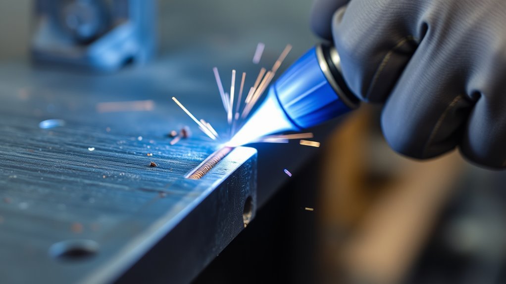
Undercut can make an otherwise smooth weld bead a weak point. It appears as a narrow groove beside the weld, usually at the toe where the bead meets the base metal. The groove removes supporting metal, creates a sharp change in shape, and can give fatigue cracks a place to start. This guide explains how to identify, prevent, measure, and repair undercut without confusing it with other weld defects.
Quick Answer
Undercut in welding is a groove melted into the base metal at a weld toe or root and left unfilled by weld metal. It reduces the effective section and creates a stress concentration. Prevent it by balancing current, voltage, arc length, travel speed, work angle, travel angle, and filler deposition for the process and joint.
Key Takeaways
- Undercut is a geometric groove at the weld toe or root; it is not the same defect as lack of fusion.
- Common causes include excessive current or voltage, a long arc, fast travel, incorrect work or travel angle, poor puddle control, and insufficient metal at the toes.
- A typical travel-angle starting range is about 5–15 degrees, but the correct work angle depends on the joint, position, process, and welding procedure.
- There is no universal acceptable depth. Compare every indication with the applicable drawing, welding procedure, contract specification, or code.
- Code-governed or safety-critical repairs should follow an approved repair procedure and receive the required final inspection.
At a Glance
| Time Required | About 5–15 minutes for basic visual inspection; longer when grinding, rewelding, NDT, or formal documentation is required |
| Difficulty | Basic to identify; intermediate to correct; qualified personnel may be required for structural or code work |
| Tools Needed | Good lighting, cleaning tools, straightedge or weld-profile gauge, approved PPE, and repair equipment when permitted |
| Cost | Low for inspection or a practice coupon; potentially much higher when a formal repair, inspector, or nondestructive examination is required |
What’s in This Article
- How Undercut Forms at the Weld Toe
- Types of Welding Undercut
- How Undercut Weakens Welds
- Undercut vs. Other Weld Defects
- Common Causes of Undercut
- Welding Settings That Cause Undercut
- Process-Specific Undercut Troubleshooting
- Joint Prep Mistakes That Lead to Undercut
- How to Spot Undercut Early
- How to Measure Undercut
- How Much Undercut Is Acceptable?
- How to Prevent Undercut in Welding
- Set the Right Electrode Angle
- Pick the Right Filler and Shielding Gas
- How to Fix Undercut in Welds
- Undercut Troubleshooting Checklist
- Frequently Asked Questions
- Conclusion
- Sources
How Undercut Forms at the Weld Toe
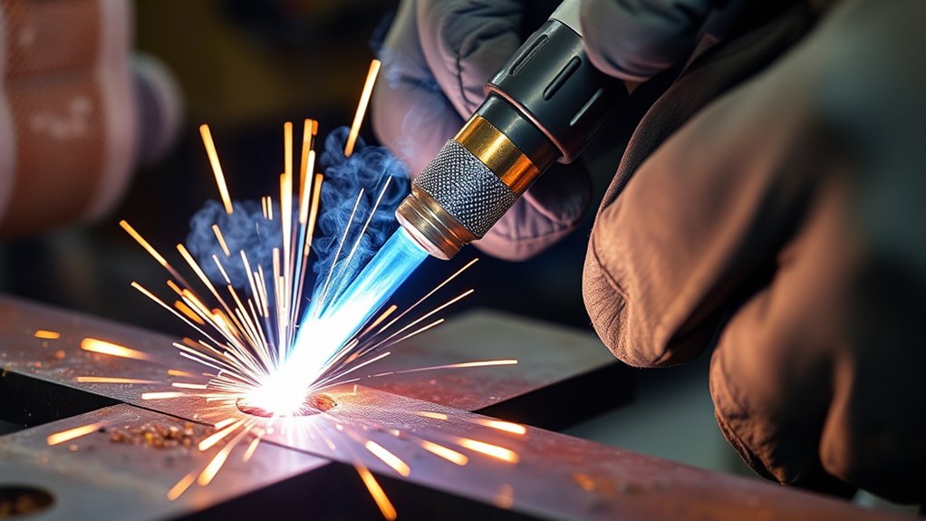
Undercut is a groove or depression melted into the base metal beside a weld bead and left unfilled by weld metal. It most often appears at the weld toe, but it can also occur along the root side of a joint or beside an earlier bead in a multipass weld.
The defect forms when the arc melts an edge faster than the puddle can refill it. This can happen because the current or voltage is too high, the arc is too long, travel is too fast, the torch or electrode points too heavily toward one member, or the welder fails to hold enough molten metal at the toe.
This definition also covers autogenous TIG welds made without added filler. The problem is not simply that a filler rod or wire failed to reach the edge. The broader problem is that melted base metal was not replaced by the finished weld profile.
The ESAB welding-defect guide describes undercut as a groove melted into the base metal that reduces the effective section and introduces a stress raiser.
Note: Undercut is a geometric imperfection. It is not another name for lack of fusion, although both defects can occur in the same weld.
In practical terms, a visible groove means the weld profile, machine settings, positioning, or puddle control needs attention. Strong heat input monitoring can help, but you must also make sure the puddle deposits enough metal at both edges.
Types of Welding Undercut
Not every groove appears in the same place. Identifying its location helps narrow down the cause.
| Type | Where It Appears | Common Clue |
| External toe undercut | Along one or both visible edges of the finished bead | A narrow line, valley, or sharp notch beside the bead |
| Root undercut | At the root edge on the back or inside surface of a complete-joint-penetration weld | May be visible from the back side or found by the inspection method required for the joint |
| Inter-run undercut | Beside a previous bead in a multipass weld | A valley that can trap slag or remain beneath a later pass |
| Continuous undercut | Runs along a substantial part of the weld | Usually points to a persistent setting, angle, or travel problem |
| Intermittent undercut | Appears in short, separated sections | Often follows hand-position changes, inconsistent pauses, or local fit-up changes |
How Undercut Weakens Welds
Undercut removes base metal at the weld toe or root, reducing the joint’s effective cross-sectional area. The remaining section may have to carry the same service load through less metal.
The groove also creates a sharp change in shape. Instead of flowing smoothly from the base metal into the weld bead, stress becomes concentrated at the notch. This matters most in joints exposed to vibration, bending, impact, repeated loading, or changes in temperature.
You can often reduce related problems by correcting common MIG welding problems and solutions, including unstable arc length, unsuitable voltage, poor wire-feed balance, and uneven travel.
Stress Concentration Risks
A weld toe already changes the shape of the loaded part. A sharp undercut makes that transition more severe, creating a stress riser. Under repeated loading, a crack may start at the bottom of the groove and grow through the base metal or heat-affected zone.
The risk is not determined by depth alone. Groove length, sharpness, orientation, material toughness, weld location, residual stress, loading direction, corrosion, and service temperature can all affect performance.
Undercut may also make coating coverage more difficult at the weld toe. Moisture can remain in a sharp groove when surface preparation or coating is poor, which may increase local corrosion risk in exposed service.
Reduced Load Capacity
| Effect | Possible Result |
| Less metal at the toe or root | Reduced effective section |
| Sharp notch geometry | Higher local stress |
| Cyclic or vibrating load | Earlier fatigue-crack initiation |
| Poor coating coverage | Possible local corrosion initiation |
| Safety-critical service | Rejection, repair, or engineering review |
The exact strength loss cannot be stated from appearance alone. It depends on the groove dimensions, weld design, material, loading, and acceptance standard.
Warning: Do not place a load-bearing, pressure-retaining, vehicle-structural, lifting, pipeline, or other safety-critical weld into service when undercut exceeds the governing requirement or has not been evaluated by the responsible qualified person.
Undercut vs. Other Weld Defects
Several discontinuities can create a poor-looking weld edge, but they are not interchangeable. Correct identification matters because the causes, inspection methods, and repairs differ.
| Condition | What It Is | Typical Appearance |
| Undercut | Base metal melted beside the weld and left unfilled | Narrow groove at a toe or root |
| Underfill | The weld face or root is below the intended surface because insufficient weld metal was deposited | Broad depression across the weld rather than a narrow toe groove |
| Lack of fusion | Weld metal fails to fuse with the base metal or a previous bead | May be hidden below the surface and cannot be ruled out by bead appearance alone |
| Overlap or cold lap | Weld metal rolls over the base metal without proper fusion at the edge | A lip or rolled edge instead of a cut groove |
| Concave fillet profile | A smoothly curved fillet face that may or may not meet required weld size | Broad, smooth curvature without a sharp groove cut into the base metal |
Common Causes of Undercut
Undercut usually develops when the arc melts the edge faster than the puddle deposits metal there. More than one error may be present at the same time.
- Excessive current: A forceful arc digs deeply into the edge and can wash away the toe.
- Excessive voltage or long arc length: The wider arc spreads heat beyond the intended bead and can leave the edges unfilled.
- Travel speed that is too fast: The puddle does not remain at the toe long enough to refill the melted groove.
- Incorrect work angle: Too much heat is directed into one joint member, often producing undercut on one side and excess buildup on the other.
- Excessive travel angle: A steep push or drag angle can destabilize the arc and prevent smooth toe wetting.
- Poor weave control: Moving too widely or crossing the center too slowly can overheat the sides without leaving enough metal at the toes.
- Insufficient filler deposition: Wire feed, filler addition, electrode size, or manipulation may not match the amount of base metal being melted.
- Arc blow: Magnetic deflection can push the arc toward one wall and cut a groove along that edge.
- Difficult welding position: Gravity can pull the puddle away from the upper toe in horizontal or vertical welding.
Steady travel speed helps maintain a stable puddle, but speed cannot be judged alone. It must match current, voltage, wire feed, electrode size, joint size, and position.
Excessive Arc Energy and a Long Arc
Too much current can create a forceful, digging arc that erodes the toe. Excessive voltage in a constant-voltage wire process, or an excessively long arc in stick or TIG welding, can spread the arc and overheat the bead edges.
This is often described simply as “too much heat,” but the full relationship is more complex. A fast travel speed reduces calculated heat input per unit length, yet it can still cause undercut because the arc melts the edge while the puddle moves away before depositing enough metal.
Look for the complete pattern:
- A wide, flat arc with a long arc length may indicate excess voltage.
- A harsh, digging arc may indicate excessive current or arc-force settings.
- A narrow bead with poorly filled toes may indicate excessive travel speed.
- A groove on only one side may point to work-angle error or arc blow rather than an overall heat problem.
Poor Travel Technique
Even suitable machine settings can produce undercut when hand movement is inconsistent. The leading portion of the puddle should remain visible, and molten metal should reach both toes before the arc moves forward.
Moving too fast starves the bead. Moving too slowly can create an oversized puddle that becomes difficult to control, especially out of position. A very wide weave can also concentrate too much time at the sides or allow the center to sag.
Use a controlled stringer bead or a weave permitted by the procedure. When weaving, pause only long enough for the puddle to fill the toe. Do not dwell so long that the arc cuts into the sidewall.
Pro Tip: Watch the leading edge and both toes of the puddle rather than staring at the bright center of the arc. The finished bead follows the puddle, not the arc light.
Welding Settings That Cause Undercut
Machine controls affect one another, so avoid changing several settings at once. Start with the machine chart, filler-metal data sheet, or approved welding procedure, make a test weld on matching scrap, and correct one variable at a time.
| Symptom | Likely Cause | Correction to Test |
| Groove along both toes with a wide, flat bead | Voltage or arc length too high | Shorten the arc or reduce voltage within the approved range |
| Deep groove with a harsh or digging arc | Current or arc-force setting too high | Reduce current or digging action while maintaining required fusion |
| Narrow bead with incomplete toe fill | Travel speed too fast or deposition too low | Slow slightly or restore the specified wire-feed, filler-addition, or electrode range |
| Undercut on one side only | Incorrect work angle, poor access, or arc blow | Center the arc, improve body position, and correct arc blow if present |
| Irregular short sections of undercut | Changing arc length, hand angle, speed, or stickout | Brace the hands and maintain consistent electrode extension and movement |
Shielding gas remains important for GMAW and gas-shielded FCAW, but poor gas coverage more directly causes porosity, oxidation, or contamination than undercut. Set flow according to the machine manual, wire data, nozzle, and work conditions rather than treating one CFH value as universal.
Process-Specific Undercut Troubleshooting
| Process | Common Causes | Corrections |
| MIG/GMAW | Voltage too high for wire feed, excessive travel speed, steep gun angle, long stickout, or poor work angle | Return to the manufacturer chart, balance voltage and wire feed, maintain specified contact-tip-to-work distance, and use a stable work and travel angle |
| Flux-Core/FCAW | Excessive current or voltage, long electrode extension outside the wire recommendation, fast travel, excessive weave, or poor slag control | Use the wire data sheet, maintain the recommended extension and polarity, control weave width, and clean between passes |
| Stick/SMAW | Current too high, arc too long, excessive travel angle, rapid travel, or wide uncontrolled weaving | Shorten the arc, use the electrode’s recommended current range, hold a controlled travel angle, and let the puddle fill each toe |
| TIG/GTAW | Excess amperage, long arc, fast travel, torch tilted too far, insufficient filler addition, or poor heat control near an edge | Shorten the arc, reduce peak amperage when appropriate, add filler consistently, and keep the torch centered over the joint |
The correct setting still depends on material, thickness, filler classification, joint design, position, polarity, transfer mode, and required weld size. Use a qualified WPS when the job is governed by one.
Joint Prep Mistakes That Lead to Undercut
Joint preparation is not usually the only cause of toe undercut, but poor fit-up can make puddle control much harder. Excessive or inconsistent gaps, misalignment, poor access, and unsuitable bevel geometry force the welder to compensate with changing angles, heat, or filler deposition.
A large gap can increase the amount of weld metal required and may encourage burn-through or underfill. A narrow groove or restricted access can force the electrode toward one sidewall, producing uneven fusion and one-sided undercut.
Oil, rust, paint, moisture, heavy mill scale, and coating residue can disturb arc stability and wetting. Clean the joint to the degree required by the process and procedure. Removing zinc coating and residues from the weld zone may improve weld control, but removal and welding must be performed with suitable fume controls.
Choose joint dimensions that match the material thickness, welding process, and access available. Proper fit-up helps maintain controlled arc placement and supports the required fillet weld size.
Warning: Welding or cutting zinc-bearing material can produce hazardous fumes. Use appropriate local exhaust or other ventilation controls, keep your head out of the plume, wear the required PPE, and follow the applicable workplace rules. OSHA provides specific ventilation requirements for covered zinc-bearing welding operations.
How to Spot Undercut Early
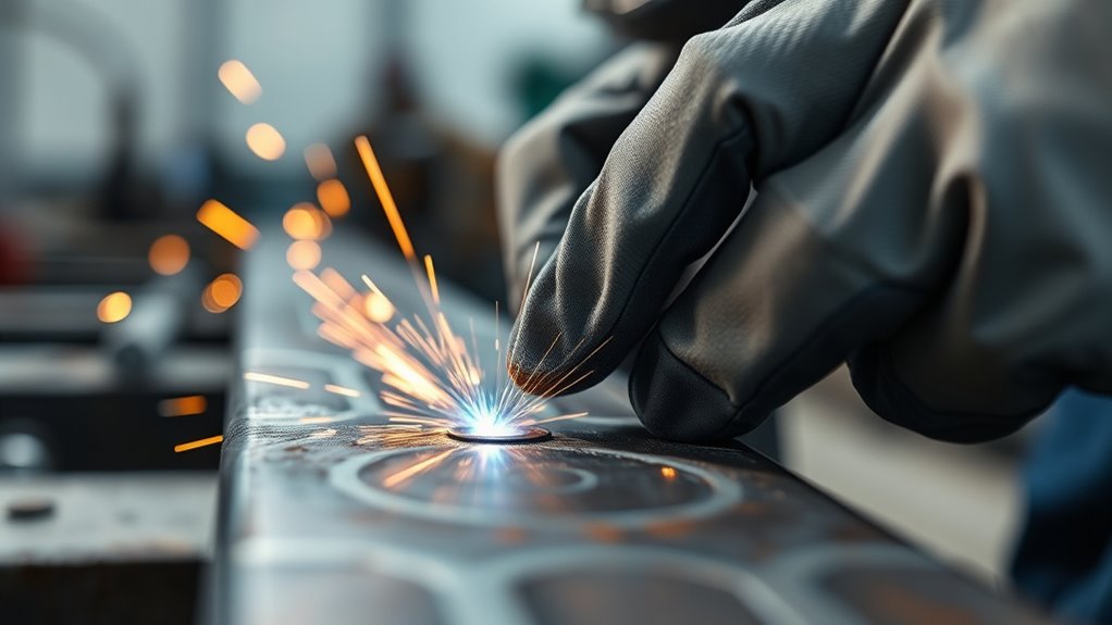
Inspect the weld toe and accessible root under clean, bright light. Undercut commonly appears as a linear groove, shallow valley, or sharp notch running beside the weld bead.
Use light from a low angle so shadows reveal abrupt changes in profile. View the weld from more than one direction because a shiny surface can hide a shallow groove.
Do not judge acceptability from appearance alone. Clean the area, measure the indication, note its length and location, and compare it with the applicable requirement.
Visual Clues to Watch
| Clue | What You May See | Next Action |
| Linear groove | A narrow line beside the bead | Clean and measure it |
| Sharp profile change | An abrupt transition rather than a smooth toe | Check whether it is undercut, overlap, or a crack |
| One-sided groove | Undercut on only the upper, lower, or one sidewall toe | Review work angle, position, and arc blow |
| Dark linear indication after cleaning | A line that may be sharper than ordinary undercut | Stop and evaluate for a possible crack |
Penetrant testing or magnetic-particle testing may be required when a surface-breaking crack is suspected or the inspection plan calls for NDT. These methods can supplement visual inspection, but they do not replace dimensional measurement of an undercut groove.
How to Measure Undercut
- Let the weld cool as required. Do not handle hot metal or apply inspection materials outside their approved temperature range.
- Remove slag, spatter, scale, and loose coating. The measuring surface must be visible without grinding away the indication.
- Provide adequate light and access. View the toe from several angles.
- Locate the deepest point. Follow the entire groove instead of measuring only the first visible section.
- Use a suitable weld-profile or bridge-cam-type gauge. Seat the gauge on sound surrounding metal and follow its instructions.
- Record depth, length, side, and location. Some acceptance rules consider both maximum depth and accumulated length.
- Compare the result with the governing requirement. Use the drawing, WPS, inspection plan, contract specification, or adopted welding code.
A fillet-weld gauge can help check weld size and profile, but not every fillet gauge accurately measures undercut depth. Use a calibrated tool intended for the required measurement.
Keep measuring surfaces clean and inspect the gauge for wear or damage. Formal quality work may also require current calibration records.
How Much Undercut Is Acceptable?
There is no single undercut depth that is acceptable for every weld. Acceptance comes from the governing code, drawing, welding procedure, quality level, or contract specification.
Do not rely on a generic internet threshold. An indication that passes on one non-critical fabrication may be rejectable on a dynamically loaded structure, pressure component, bridge, vehicle structure, lifting device, or pipeline.
AWS D1.1/D1.1M:2025-AMD1 establishes structural-steel requirements for welding, qualification, fabrication, inspection, and acceptance when that code is contractually applicable. Other projects may use a different AWS code, API standard, ASME code, military specification, OEM repair procedure, or customer standard.
ISO 5817:2023 provides multiple weld-quality levels for fusion-welded joints rather than one universal workmanship limit. The selected level and project requirements determine how an imperfection is evaluated.
Note: A discontinuity is not automatically a rejectable defect. It becomes rejectable when it exceeds the acceptance criteria that apply to the job.
How to Prevent Undercut in Welding
Prevention starts before striking the arc. Confirm the joint design, fit-up, material, filler, polarity, gas, and welding position. Then set the machine from the approved WPS or manufacturer chart and verify the setup on matching scrap when permitted.
- Use current and voltage that match the filler, material thickness, and required weld size.
- Keep stick or TIG arc length short and consistent.
- Maintain the recommended contact-tip-to-work distance for wire welding.
- Use a steady travel speed that allows the puddle to fill both toes.
- Separate work angle from travel angle and control both.
- Avoid an unnecessarily wide weave.
- Pause briefly at a toe only when the technique and procedure permit it.
- Clean between multipass beads so slag does not become trapped in a valley.
- Correct magnetic arc blow when the arc repeatedly deflects to one side.
- Stop and adjust early rather than completing a long defective pass.
Understanding suitable amperage ranges helps establish a starting point, but an amperage chart does not replace the electrode data sheet or WPS.
Products Worth Considering
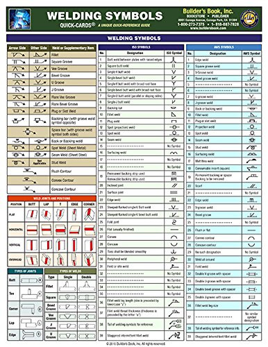

🧲 Sticks to Toolboxes & Welders – Heavy-duty magnetic welding chart adheres to metal surfaces like your welding table, toolbox, or wall for instant reference while working.
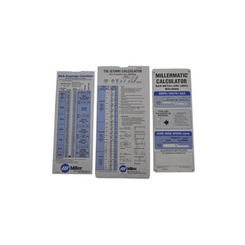
Comprehensive 3‑in‑1 reference pack covers MIG, TIG and Stick welding parameters—ideal for welders who work across multiple processes
Set the Right Electrode Angle
“Electrode angle” includes two separate measurements:
- Work angle: The side-to-side position of the electrode or gun relative to the joint members.
- Travel angle: The forward or backward tilt in the direction of travel.
For many normal MIG and stick welds, a 5–15-degree travel angle is a practical starting range. The correct work angle changes with the joint. A flat T-joint fillet commonly starts near 45 degrees between the two members, while butt and lap joints require different positioning.
Miller’s MIG welding guidance distinguishes work angle from travel angle and notes that excessive travel angles can increase instability. Its stick welding guidance gives process- and position-specific angle recommendations rather than one universal value.
Use these as starting points only. Follow the WPS, electrode instructions, and joint requirements when they specify a different angle.
- Center the arc in a groove weld unless the procedure calls for sidewall manipulation.
- Split the work angle evenly in a symmetrical fillet unless one member requires bias.
- Reduce excessive push or drag angle.
- Reposition your body instead of twisting the wrist as the bead progresses.
- Check the puddle for equal wetting at both toes.
Strong heat control is especially important on thin material, where the correction for undercut must not create burn-through.
Pick the Right Filler and Shielding Gas
Match the filler classification, diameter, polarity, and shielding gas to the base material and required mechanical properties. The filler manufacturer’s data sheet and the approved WPS should take priority over generic settings.
A larger wire or electrode is not automatically hotter, and a smaller one is not automatically safer. Each diameter has a usable current and deposition range. Problems develop when the chosen diameter cannot deliver the required weld size efficiently or is operated outside its recommended range.
For mild-steel GMAW, argon-carbon-dioxide blends are commonly used because they support a stable arc and smooth bead profile. Pure carbon dioxide and other blends may also be specified depending on penetration, transfer mode, cost, and procedure requirements.
Set gas flow from the machine manual, torch setup, wire data, and work environment. Miller’s general mild-steel MIG instructions use 20–25 cubic feet per hour as one starting range, but nozzle size, transfer mode, gas type, drafts, and equipment can require a different value.
Too little gas can allow atmospheric contamination. Excessive flow can create turbulence and waste gas. Check the cylinder, regulator, hoses, connections, diffuser, and nozzle when shielding is unstable.
Adjusting wire speed and voltage as a balanced pair can improve bead shape and reduce toe erosion.
How to Fix Undercut in Welds
The correct repair depends on the groove dimensions, associated discontinuities, material, service, and governing specification. Do not begin by covering the groove with another bead until you know what the procedure permits.
- Stop and identify the requirement. Determine whether the weld is cosmetic, non-critical, structural, pressure-retaining, vehicle-related, or otherwise code-governed.
- Clean and measure the full indication. Record its depth, length, side, and location.
- Check for associated cracks or trapped slag. Use the inspection method required by the repair plan. PT or MT may be needed for surface-breaking cracks, but neither substitutes for dimensional measurement.
- Obtain repair authorization when required. Code work may require approval from the inspector, engineer, manufacturer, or responsible quality representative.
- Remove rejectable material as directed. Grinding, machining, or approved gouging may be required until the complete rejectable area is removed without reducing the remaining base metal below its permitted thickness.
- Prepare a smooth repair area. Remove sharp notches, contamination, slag, and grinding debris.
- Reweld with the approved filler and procedure. Correct the original current, voltage, arc length, angle, travel, fit-up, or arc-blow problem before making the repair pass.
- Blend only as permitted. Grinding must not reduce the weld or base metal below the required dimensions.
- Perform final inspection. Repeat the required visual, dimensional, and nondestructive examinations.
- Document the repair when required. Record the location, removal method, WPS, welder, inspection results, and disposition.
A shallow groove on a non-code practice piece may sometimes be corrected with a controlled toe pass. A deeper groove, possible crack, trapped slag pocket, or safety-critical weld may require complete excavation and rewelding.
Mastering the key welding parameters helps prevent the same defect from returning.
Warning: Grinding and rewelding expose you to sparks, hot metal, wheel fragments, arc radiation, electric shock, fire, noise, and fumes. Inspect the grinder and wheel, use the guard and correct wheel rating, wear suitable eye, face, hearing, hand, body, and respiratory protection, control nearby combustibles, and follow the equipment instructions and workplace procedure.
Products Worth Considering
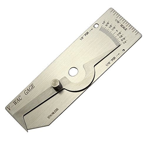
V-WAC Single Weld Gage

Angle of Preparation, 0° to 60° and Excess Weld Metal (capping size)

❤WELD GAUGE SET❤ Package Includes 1 x Undercuts Checking Gauge, 1 x Convexity Concavity Checking Gauge, 2 x Instructions, 2 x Pouches. These Gauges with Imperial Measurement Is Suitable for Welding Inspection.
Undercut Troubleshooting Checklist
Use this order so you do not chase machine settings when the real problem is positioning or access:
- Confirm the correct material, filler, polarity, gas, joint, and WPS.
- Check joint cleanliness, alignment, gap, bevel, and access.
- Verify current, voltage, wire feed, arc-force setting, and transfer mode.
- Check arc length, contact-tip-to-work distance, or electrode extension.
- Separate work angle from travel angle and correct both.
- Watch whether the puddle reaches each toe before moving forward.
- Reduce excessive travel speed or restore required deposition.
- Check for magnetic arc blow if the groove stays on one side.
- Make one small correction at a time on matching scrap.
- Inspect the new bead before continuing the production weld.
Frequently Asked Questions
How do you avoid getting undercut?
Use the specified current, voltage, arc length, electrode extension, work angle, travel angle, and travel speed. Keep the joint clean, watch both puddle toes, and make sure the weld deposits enough metal to refill the edges being melted.
What does undercut look like on a weld?
Undercut usually looks like a narrow groove, notch, or valley along a weld toe. It may run continuously beside the bead or appear in short sections. Root undercut can appear on the back or inside surface of a complete-joint-penetration weld.
Can you leave small undercut in a weld?
Only when it meets the applicable drawing, welding procedure, contract specification, or code. There is no universal acceptable depth. Safety-critical and fatigue-loaded welds may have stricter limits than ordinary non-critical fabrication.
Is undercut worse than porosity?
Neither defect is automatically worse in every application. Undercut removes section and creates a sharp surface stress riser, while porosity creates gas cavities in the weld metal. Acceptability depends on size, location, quantity, loading, material, and the governing standard.
What is the fastest way to repair undercut?
The fastest safe method is the one permitted by the repair procedure. A minor groove may allow a corrective toe pass, while deeper or cracked areas may require grinding or approved gouging, rewelding, and reinspection. Covering a rejectable groove without evaluating it can hide a more serious problem.
Is undercut the same as lack of fusion?
No. Undercut is a groove melted into the base metal and left unfilled. Lack of fusion means the weld metal did not fuse properly with the base metal or a previous weld bead. The two discontinuities can occur together but require separate evaluation.
Can you grind undercut out?
Grinding may be part of an approved repair, but it must remove the rejectable area without reducing the weld or base metal below required dimensions. A ground area may still require rewelding and final inspection. Do not grind a safety-critical weld without the applicable repair instructions.
Can undercut occur inside a weld?
Undercut can occur at an inaccessible root or between runs in a multipass weld. External toe undercut is visible from the weld face, while root or inter-run undercut may require access from the opposite side or the inspection method specified for the joint.
Conclusion
Undercut forms when the arc melts a weld edge and the finished puddle does not refill it. The best prevention is not one magic amperage or angle. It is a balanced combination of joint preparation, approved settings, short and stable arc length, suitable work and travel angles, steady travel, and enough deposition at both toes.
Inspect the complete weld under good light, measure any groove with an appropriate gauge, and compare it with the actual project requirement. When repair is necessary, remove or refill the defect only through a method allowed by the applicable procedure, then perform the required final inspection before the weld enters service.
Sources
- ESAB Welding Defects Guide — supports the definition, structural effects, primary causes, prevention, and repair principles for undercut.
- Miller: Five Steps to Improving Your Stick Welding Technique — supports arc-length, travel-angle, travel-speed, and puddle-control guidance.
- Miller: MIG Welding for Mild Steel — supports MIG work-angle, travel-angle, gas-flow, and joint-position guidance.
- American Welding Society: AWS D1.1/D1.1M:2025-AMD1 — supports the need to use the applicable structural-welding inspection and acceptance criteria.
- ISO 5817:2023 — supports the use of selected quality levels for imperfections in fusion-welded joints rather than a universal limit.
- OSHA 29 CFR 1910.252 — supports welding-fume and ventilation precautions, including requirements involving zinc-bearing materials.