
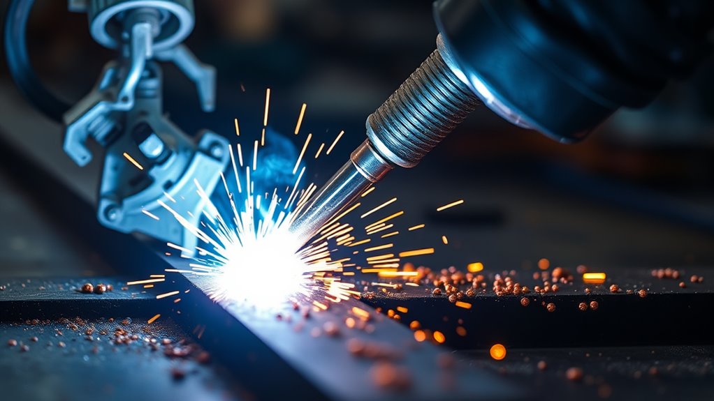
Weld spatter can turn a sound weld into extra scraping, grinding, and rework. Those small metal droplets are also a useful warning: the transfer mode, voltage, wire feed speed, shielding gas, consumables, surface condition, or gun technique may need attention. This guide explains what weld spatter is, why GMAW creates it, how the main transfer modes compare, and how to diagnose and reduce excessive spatter safely.
Quick Answer
Weld spatter is molten metal expelled from the arc or weld pool that cools and sticks near the bead. In GMAW, excessive spatter usually points to unstable metal transfer, mismatched voltage and wire feed speed, excessive stickout, poor gas coverage, dirty metal or wire, worn consumables, or incorrect technique.
Key Takeaways
- A small amount of spatter can occur in several arc-welding processes, but a sudden or heavy increase deserves troubleshooting.
- Short-circuit GMAW normally produces more spatter than properly tuned spray or pulsed-spray transfer; globular transfer is often the messiest conventional mode.
- On a typical constant-voltage MIG welder, wire feed speed largely controls current, while voltage controls arc length.
- Clean metal, correct polarity, sound consumables, steady gas coverage, consistent stickout, and matched settings are the main controls.
- Anti-spatter spray or gel reduces adhesion and cleanup, but it does not correct an unstable arc or a defective weld.
- Spatter is hot enough to burn skin and start fires, so use proper PPE and control the hot-work area before welding or cleanup.
At a Glance
| Time Required | About 10–30 minutes for basic diagnosis and test welds |
| Difficulty | Beginner to intermediate; production or code work may require a qualified welding supervisor |
| Tools Needed | PPE, wire brush or grinder, MIG pliers or nozzle reamer, clean test coupons, and the machine or wire setting chart |
| Cost | Often limited to cleaning supplies or replacement consumables; cost varies by the fault found |
What Is Weld Spatter?
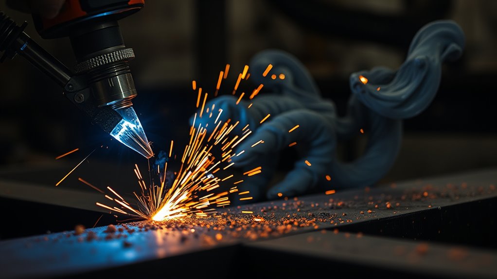
Weld spatter is the scattering of molten metal particles that cool into solid droplets near a weld bead. The droplets may land on the workpiece, fixtures, clamps, welding gun, floor, clothing, or nearby equipment. The Miller GMAW troubleshooting guide uses this same basic definition for excessive spatter.
Spatter is more than a cleanup problem: it is often the visible result of unstable metal transfer or poor process control.
You may see spatter in GMAW/MIG, flux-cored arc welding, shielded metal arc welding, and some other arc processes. Gas tungsten arc welding normally runs with very little spatter because it uses a nonconsumable tungsten electrode; noticeable TIG spatter usually points to contamination, unstable shielding, or contact between the tungsten, filler, and weld pool.
Spatter is different from slag. Spatter consists of separate metal droplets thrown from the arc. Slag is the solidified flux layer left over a weld by processes such as stick welding and many flux-cored wires. Both may require cleanup, but they have different causes.
Is Weld Spatter a Weld Defect?
Spatter on the surface does not prove that a weld will fail. A weld can have scattered droplets and still have acceptable fusion and strength. However, heavy spatter often appears with unstable settings, poor shielding, contamination, erratic wire feeding, or bad technique. Those same conditions can also contribute to porosity, lack of fusion, undercut, or an irregular bead.
Acceptance depends on the drawing, customer specification, welding procedure specification, and applicable code. On cosmetic, painted, machined, sealing, or close-fit parts, even harmless surface droplets can be unacceptable because they interfere with appearance, coating, assembly, or inspection. Do not judge weld soundness from spatter alone; inspect the bead and follow the required acceptance criteria.
Why GMAW Produces Weld Spatter
Gas metal arc welding (GMAW) forms an arc between a continuously fed consumable wire and the workpiece. The arc melts the wire and base metal, while shielding gas protects the molten pool. Spatter forms when droplets detach violently, a short circuit breaks harshly, gas or contamination disturbs the pool, or the wire feed becomes erratic.
On a common constant-voltage GMAW power source, the operator normally sets voltage and wire feed speed. Wire feed speed and current are closely linked, so amperage is not usually a third fully independent control. As EWI explains, wire feed speed is the primary way the operator changes current on a typical CV system, while voltage mainly changes arc length.
When the wire feed rate, burnoff rate, and arc length do not balance, the arc may pop, stub the wire into the pool, form oversized droplets, or burn back toward the contact tip. Surface contaminants such as oil, rust, paint, moisture, and undercoating can also vaporize and disrupt the pool. Weak shielding caused by low flow, leaks, drafts, or a clogged nozzle allows air to enter the weld zone.
Note: More shielding-gas flow is not always better. Set the rate recommended by the machine, wire, and gas supplier. Excessive flow can create turbulence and pull surrounding air into the gas stream.
Short Circuit, Globular, Spray, and Pulsed-Spray Transfer
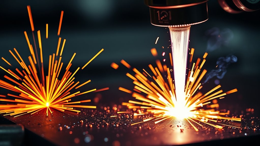
GMAW transfer mode depends on the wire, wire diameter, shielding gas, voltage, current, wire feed speed, and machine waveform. Each mode has a different spatter tendency and usable range.
| Transfer mode | How metal transfers | Typical spatter | Main use and limits |
| Short circuit | The wire repeatedly touches the pool, shorts, pinches off, and re-establishes the arc. | Moderate; can become heavy when voltage, wire feed speed, inductance, or stickout is wrong | Thin metal, root work, and all positions; low heat and deposition, with fusion concerns on thicker joints |
| Globular | Large drops form at the wire tip and fall or splash into the pool. | High; often the least desirable conventional mode for appearance and cleanup | Transition range between short circuit and spray; generally limited to flat and horizontal work |
| Spray | A steady stream of fine droplets crosses the arc without repeated short circuits. | Very low when the gas and parameters support true spray transfer | High deposition and heat; normally uses argon-rich gas and is mainly suited to thicker material in flat or horizontal positions |
| Pulsed spray | Peak current detaches a controlled droplet; lower background current keeps the arc lit between pulses. | Very low across a wider operating range | Cleaner transfer with lower average heat and better out-of-position control, but it requires a pulse-capable machine and the correct program |
The Miller transfer-mode guide identifies more spatter as a limitation of short-circuit transfer, spatter as a limitation of globular transfer, and very little spatter as an advantage of spray transfer. Pulsed GMAW avoids the globular range and can reduce spatter while improving puddle control.
Which GMAW Transfer Mode Produces the Least Spatter?
Properly tuned spray and pulsed-spray transfer are both low-spatter choices. Pulsed spray is often the better practical option when you need low spatter with lower average heat, thinner material, or out-of-position welding. Conventional spray can be extremely clean on suitable thicker material, but it needs enough current, an argon-rich shielding gas, good fit-up, and a position where the fluid pool can be controlled.
Controlled or modified short-circuit processes can also reduce spatter on thin material, but they depend on machine-specific waveform control. Use the approved program and follow the equipment manufacturer’s procedure rather than copying a generic setting.
Main Causes of Weld Spatter
Excessive spatter usually has more than one possible cause. Start with the sound and behavior of the arc, then inspect settings, gas delivery, wire feeding, consumables, work connection, and material condition.
| What you notice | Likely causes | First checks |
| Wire stubs into the plate with hard popping | Wire feed speed too high for the voltage, voltage too low, or poor wire feeding | Confirm the chart setting; adjust one variable at a time; inspect drive rolls, liner, and tip |
| Long, harsh arc with fine spatter | Voltage too high, travel speed too high, or excessive arc length | Return to the recommended voltage and keep a steady contact-tip-to-work distance |
| Spatter increases as the gun moves away | Stickout or contact-tip-to-work distance is too long or inconsistent | Shorten and steady the stickout using the wire or machine recommendation |
| Erratic arc and irregular wire motion | Worn or wrong-size contact tip, dirty liner, incorrect drive-roll tension, rusty wire, or poor work connection | Replace damaged consumables, correct wire tension, use clean dry wire, and secure the work clamp to clean metal |
| Spatter with porosity or a dirty-looking bead | Oil, rust, paint, moisture, dirty wire, low gas flow, leaks, drafts, or clogged nozzle | Clean the joint, inspect gas delivery, remove nozzle buildup, and protect the arc from drafts |
| Spatter begins after changing wire or process | Wrong polarity, wrong shielding gas, wrong wire diameter, or unsuitable program | Read the wire label and machine manual; verify polarity and select the correct process program |
| More spatter with 100% CO₂ on mild steel | The gas produces a more forceful, less smooth transfer than common argon/CO₂ blends | Use the gas approved for the wire and required penetration; do not change gas on qualified work without approval |
Other causes include an extreme gun angle, inconsistent travel speed, magnetic arc blow near corners or the end of a joint, and an incorrect inductance or arc-control setting. The machine’s wire-speed and voltage chart is a starting point, not a substitute for the exact wire data, shielding gas, joint, position, and approved welding procedure.
How to Reduce Weld Spatter
Use a controlled troubleshooting sequence. Make one change at a time and test on clean scrap of the same material, thickness, joint type, wire, and gas whenever possible.
Products Worth Considering

Category: Welding -- Welding Chemicals

Heavy-Duty, Industrial Anti-Spatter Protection: Sprayman’s Anti-Spatter Welding Spray prevents spatter adhesion on Arc, MIG abd TIG Welding Equipment, including nozzles, torches, and tools.

𝗛𝗘𝗔𝗩𝗬 𝗗𝗨𝗧𝗬 𝗦𝗢𝗟𝗩𝗘𝗡𝗧 𝗕𝗔𝗦𝗘𝗗 𝗔𝗡𝗧𝗜-𝗦𝗣𝗔𝗧𝗧𝗘𝗥: Akfix A90 Anti Spatter Spray provides robust protection against welding spatter, ensuring your workspace remains clean and efficient.
1. Start With the Approved Setup
Check the machine door chart, owner’s manual, wire classification, wire diameter, shielding-gas requirement, material thickness, joint position, and welding procedure. Confirm that the selected transfer mode is suitable for the work. For production or code welding, stay within the qualified procedure and obtain approval before changing gas, wire, polarity, or transfer mode.
2. Clean Materials Thoroughly
Remove oil, grease, moisture, rust, paint, mill contamination, and undercoating from the joint and the area where the work clamp attaches. Use a dedicated brush, suitable abrasive, or an approved cleaner. Let flammable cleaners fully evaporate and keep chlorinated solvent vapors away from welding. Inspect the wire too; rusty, oily, or damp wire can destabilize the arc.
Galvanized steel needs additional fume controls. Removing zinc near the joint may improve arc behavior, but it does not eliminate all exposure. Welding heated zinc can produce zinc-oxide fume associated with metal fume fever, so follow ventilation, respiratory-protection, and workplace requirements. Review the full galvanized-steel welding procedure before starting.
3. Inspect the Wire Path and Consumables
Verify the wire size, drive-roll groove, spool tension, drive-roll pressure, liner condition, contact-tip size, nozzle condition, and diffuser. Replace a worn, oversized, burned, or loose contact tip. Remove spatter that blocks the nozzle because restricted gas flow can create further instability and porosity.
4. Verify Polarity and the Work Connection
Use the polarity printed on the wire package or required by the procedure. Solid GMAW wire commonly uses electrode positive, while many self-shielded flux-cored wires use electrode negative; the wire manufacturer’s instructions control. Clamp to clean metal near the weld and tighten loose cable connections.
5. Check Shielding Gas Coverage
Confirm the gas type, cylinder supply, regulator or flowmeter setting, hose condition, gun connection, and solenoid operation. Check for leaks and keep fans or outdoor wind from stripping gas away. Clean the nozzle and maintain the specified nozzle-to-work distance. Do not keep raising the flow rate without diagnosis because turbulence can draw air into the shield.
6. Optimize Welding Parameters
Begin at the recommended voltage and wire feed speed. On short-circuit GMAW, harsh stubbing often means the wire is arriving too fast for the arc setting, while a long harsh arc can indicate excessive voltage. Adjust in small steps and listen for a steady, repeatable arc. On machines with inductance or arc control, use the manufacturer’s starting value before fine-tuning.
- Set voltage and wire feed speed from the chart or welding procedure.
- Run a short bead on a clean test coupon.
- Change only one control at a time.
- Check arc sound, spatter, bead shape, fusion, and penetration—not appearance alone.
- Record the final settings when the result meets the required standard.
Pro Tip: If the arc changed suddenly after it had been welding well, inspect the contact tip, nozzle, wire feed, gas supply, and work clamp before changing the machine settings. A hardware fault can make a correct setting look wrong.
7. Keep Stickout, Angle, and Travel Steady
Maintain the contact-tip-to-work distance recommended for the process. Avoid letting the gun drift farther from the joint. Keep a consistent work angle and a modest travel angle, then move at a steady speed. Extreme push or drag angles can reduce shielding and make the pool harder to control.
8. Use Anti-Spatter Protection When Appropriate
After the arc is stable, anti-spatter spray, liquid, paste, or nozzle gel can keep droplets from bonding tightly to nearby surfaces. Apply only as directed. Use a light, even coating where needed and avoid flooding the joint or any surface where residue could affect fusion, paint, plating, sealing, or inspection.
For self-shielded wire, settings and technique differ from solid-wire GMAW. Use the correct polarity and consult a process-specific flux-core spatter guide or the wire manufacturer’s data sheet.
How Spatter Differs by Welding Process
- GMAW/MIG: Spatter depends heavily on transfer mode, gas, voltage, wire feed speed, stickout, and wire-feed stability.
- Flux-cored arc welding: Spatter varies by wire type, polarity, voltage, and technique. Gas-shielded and self-shielded wires are not set up the same way. See what flux-core welding is used for and follow the correct flux-core settings.
- Shielded metal arc welding: Spatter depends on electrode type, current, polarity, arc length, and moisture condition. Slag cleanup is separate from spatter cleanup.
- Gas tungsten arc welding: TIG normally produces little spatter. If droplets appear, stop and check surface cleanliness, gas coverage, tungsten contamination, arc length, and whether the tungsten or filler touched the pool.
Beginners using flux-cored wire should also review basic flux-core technique because drag angle, stickout, polarity, and voltage requirements can differ from solid-wire MIG.
Anti-Spatter Products That Help
Anti-spatter products form a temporary barrier that reduces adhesion to workpieces, fixtures, clamps, gas nozzles, and contact tips. They can shorten cleanup time and help prevent nozzle buildup from disrupting gas flow. Common forms include water-based sprays, solvent or aerosol products, bulk liquids for automated systems, pastes, and nozzle gels.
Choose a product for the material and the next manufacturing step. Check whether it is silicone-free, paint-compatible, nonflammable, or approved for the specific coating or inspection process. Product claims vary, so read the technical data sheet and safety data sheet rather than assuming every anti-spatter product is interchangeable.
Warning: Never spray an aerosol into an active arc or onto hot metal unless the product instructions specifically permit it. Some aerosols are flammable or pressurized. Keep the container away from sparks and heat, allow required drying time, and follow the label and safety data sheet.
Anti-spatter protection can limit buildup and protect consumables, but it cannot correct wrong polarity, unstable wire feeding, dirty metal, weak shielding, or mismatched settings. Treat it as a cleanup aid after the welding process is under control.
Products Worth Considering

Gel eliminates erratic operation with a film that will not clog orifices and threads on MIG nozzles and contact tips
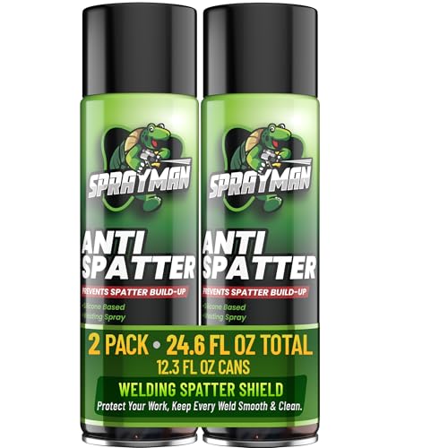
Heavy-Duty, Industrial Anti-Spatter Protection: Sprayman’s Anti-Spatter Welding Spray prevents spatter adhesion on Arc, MIG abd TIG Welding Equipment, including nozzles, torches, and tools.
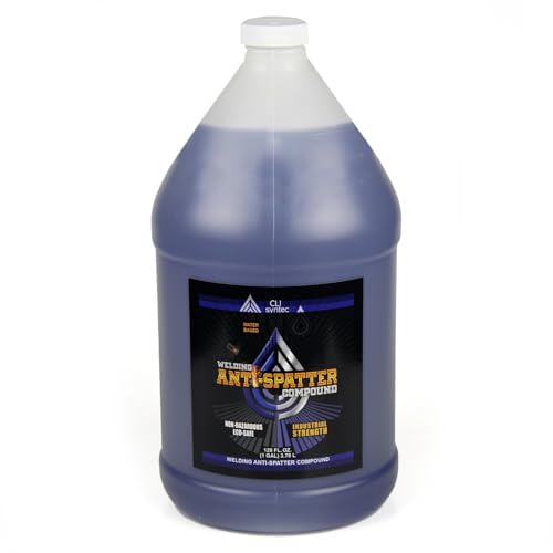
Water-Based Non-Hazardous Formula: This welding compound is water-based and non-hazardous, making it safer to handle and store in your workspace
How to Remove Weld Spatter Safely
Let the work cool to a safe handling temperature, switch off or isolate equipment as required, and wear safety glasses with side protection. Chipping and grinding can launch sharp metal even after the arc is off.
- Remove loose droplets with MIG pliers, a hand scraper, chisel, or spatter tool.
- Use a wire brush for light residue that does not require cutting into the base metal.
- Use a file, flap disc, or grinder only when needed, with the correct guard and abrasive for the material.
- Protect machined edges, thin sheet, sealing faces, and finished surfaces from gouging or overheating.
- Clean away grinding dust and confirm that the finished surface meets the drawing or coating requirement.
Grinding creates its own flying-particle, noise, dust, and fire hazards. Follow the tool manual and appropriate PPE. A broader hot-work PPE and setup checklist can help you review the surrounding work area.
When Weld Spatter Needs More Attention
Light, consistent spatter may be normal for the selected process. Stop and investigate when spatter suddenly increases, the wire begins stubbing or burning back, the gas nozzle clogs quickly, the arc becomes erratic, or the bead also shows porosity, undercut, lack of fusion, excessive convexity, or irregular penetration.
Check the bead, nozzle, contact tip, diffuser, liner, drive rolls, shielding gas, work clamp, wire, and workpiece before continuing. A structured MIG troubleshooting guide can help separate spatter from porosity, burnback, birdnesting, and bead-shape problems.
On load-bearing, pressure-containing, vehicle, structural, or code work, do not accept a weld based only on appearance. Follow the welding procedure and required inspection method, and involve a qualified welding inspector or supervisor when the cause is not clear.
Weld Spatter Safety
Spatter and sparks can burn skin, ignite combustible material, damage hoses, and enter shoes or clothing. OSHA’s welding requirements call for arc-welding helmets or hand shields, suitable protective clothing, ventilation where required, and hot-work controls. Eye and face protection must also address flying particles, molten metal, and injurious light; a welding helmet is normally worn over primary safety glasses or goggles where impact hazards exist.
- Remove or protect combustibles and check where sparks can travel, including cracks and the hidden side of walls, floors, or partitions.
- Wear a helmet with the correct filter shade, safety glasses with side protection, flame-resistant clothing, welding gloves, and suitable footwear.
- Use local exhaust or other required ventilation, especially on coated, painted, stainless, or galvanized metal.
- Do not weld on closed or previously used containers unless they have been properly cleaned, vented, and made safe under an approved procedure.
- Keep cylinders secured and away from sparks, heat, and electrical circuits.
The NIOSH Pocket Guide for zinc oxide lists metal fume fever symptoms such as fever, chills, cough, nausea, and chest tightness. Leave the exposure area and follow workplace medical procedures if welding-fume symptoms occur.
Safety Disclaimer: This article is for general information and does not replace hands-on welding training, an approved welding procedure, the equipment and consumable manuals, a product safety data sheet, or workplace safety rules. Use qualified supervision when the work affects structural integrity or public safety.
Frequently Asked Questions
What is weld spatter, and what problems can it cause?
Weld spatter is molten metal expelled from the arc or weld pool that solidifies near the bead. It increases cleanup, affects appearance, can interfere with fit or coating, clogs gun nozzles, and may signal unstable settings, contamination, or poor shielding.
Why do welders need eye protection around spatter?
Spatter and cleanup tools create flying-particle and molten-metal hazards, while the arc produces intense visible, ultraviolet, and infrared radiation. Use the correct welding helmet and filter shade plus primary safety glasses or goggles with suitable side protection.
Does more spatter mean the weld is bad?
Not automatically. Surface droplets do not prove that a weld lacks strength, but heavy or increasing spatter is a reason to check settings, shielding gas, cleanliness, polarity, wire feeding, consumables, and technique. Inspect the bead and apply the required acceptance criteria.
Can anti-spatter spray fix poor welding settings?
No. It can reduce how firmly droplets stick, but it cannot correct wrong polarity, mismatched voltage and wire feed speed, contaminated metal, worn consumables, or weak shielding. Fix the process first, then use anti-spatter as a cleanup aid.
Which GMAW transfer mode creates the least spatter?
Properly tuned spray and pulsed-spray transfer both produce very little spatter. Pulsed spray is often more flexible because it can provide clean transfer with lower average heat and better out-of-position control. The best choice still depends on material, thickness, gas, joint, position, and equipment.
What is the difference between spatter and slag?
Spatter is made of separate metal droplets thrown from the arc. Slag is the solidified flux layer that covers a weld made with processes such as stick welding or many flux-cored wires. They require different cleanup and have different root causes.
Why can 100% CO₂ produce more MIG spatter?
Pure CO₂ commonly produces a more forceful, less smooth transfer on mild steel than an argon/CO₂ blend, so spatter and bead roughness can increase. CO₂ may still be selected for cost or penetration, and the approved wire and procedure should determine the gas.
Can weld spatter be prevented completely?
Some optimized spray, pulsed, or controlled short-circuit applications can run with almost no visible spatter, but complete elimination is not realistic for every process and joint. The practical goal is stable transfer, an acceptable weld, and the minimum cleanup allowed by the procedure.
Sources
- American Welding Society: What Is GMAW? — GMAW definition, arc operation, shielding gas, and basic setup.
- Miller: Guidelines for Gas Metal Arc Welding — transfer modes, spatter tendencies, and excessive-spatter troubleshooting.
- Miller: Guide to Pulsed MIG Welding — pulsed-spray operation, gas requirements, heat control, and spatter reduction.
- EWI: GMAW Current and Voltage Basics — the relationship between wire feed speed, current, voltage, and arc stability on CV systems.
- OSHA 29 CFR 1910.252 — welding eye protection, clothing, ventilation, coated-metal, fire, and container requirements.
- NIOSH Pocket Guide: Zinc Oxide — zinc-oxide exposure limits, symptoms, target organs, and respiratory guidance.
Conclusion
Weld spatter is expelled molten metal, but it is also feedback from the welding process. Short-circuit transfer normally creates more spatter than a well-tuned spray or pulsed-spray arc, while globular transfer can be especially messy. Start with the approved wire, gas, polarity, and settings; clean the work; inspect the wire path and consumables; protect gas coverage; and keep stickout and travel steady. Use anti-spatter products only after the arc is stable. When spatter rises suddenly or appears with other weld problems, stop and correct the cause before continuing.




